
Hardware Installation Guide
Page 6
... DC Power Connector 1-21 Cisco RPS Connector 1-22 Console Port 1-23 2 C H A P T E R Installation 2-1 Preparing for Installation 2-1 Warnings 2-1 EMC Regulatory Statements 2-4 U.S.A. 2-4 Taiwan 2-4 Japan 2-5 Korea 2-5 Hungary 2-6 Installation Guidelines 2-6 Verifying Package Contents 2-7 Installing the Switch on a Table or Shelf 2-9 Installing the Switch in a Rack 2-9 Removing Screws from the Switch 2-11 Attaching the Brackets to a Catalyst 2912 XL, 2924C XL...
... DC Power Connector 1-21 Cisco RPS Connector 1-22 Console Port 1-23 2 C H A P T E R Installation 2-1 Preparing for Installation 2-1 Warnings 2-1 EMC Regulatory Statements 2-4 U.S.A. 2-4 Taiwan 2-4 Japan 2-5 Korea 2-5 Hungary 2-6 Installation Guidelines 2-6 Verifying Package Contents 2-7 Installing the Switch on a Table or Shelf 2-9 Installing the Switch in a Rack 2-9 Removing Screws from the Switch 2-11 Attaching the Brackets to a Catalyst 2912 XL, 2924C XL...

Hardware Installation Guide
Page 7
...18 Attaching the Optional Cable Guide 2-19 Installing the Switch on a Wall 2-20 Attaching the Brackets to the Switch 2-21 Mounting the Switch to a Wall 2-22 Powering On the Switch and Running POST 2-24 Connecting to DC Power 2-25 Preparing for Installation 2-25 Grounding the Switch 2-26 Wiring the DC-Input Power Source 2-29... Correcting Module POST Failures 3-2 Diagnosing Problems 3-3 Technical Specifications A-1 Connectors and Cable Specifications B-1 Connector Specifications B-1 10/100 Ports B-1 100BASE-FX Ports B-2 Contents 78-6461-04 Catalyst 2900 Series XL Hardware Installation Guide vii
...18 Attaching the Optional Cable Guide 2-19 Installing the Switch on a Wall 2-20 Attaching the Brackets to the Switch 2-21 Mounting the Switch to a Wall 2-22 Powering On the Switch and Running POST 2-24 Connecting to DC Power 2-25 Preparing for Installation 2-25 Grounding the Switch 2-26 Wiring the DC-Input Power Source 2-29... Correcting Module POST Failures 3-2 Diagnosing Problems 3-3 Technical Specifications A-1 Connectors and Cable Specifications B-1 Connector Specifications B-1 10/100 Ports B-1 100BASE-FX Ports B-2 Contents 78-6461-04 Catalyst 2900 Series XL Hardware Installation Guide vii

Hardware Installation Guide
Page 9
INDEX Class 1 Laser Product Warning C-22 Laser Beam Exposure Warning C-23 No On/Off Switch Warning C-24 Chassis Warning-Rack-Mounting and Servicing C-25 Reinforced Insulation Warning C-29 LAN Connections Only Warning C-30 No Field-Replaceable Units Warning C-31 Installation Warning C-32 SELV Source Warning C-33 Restricted Access Warning C-34 Shielded Ethernet Cables...Equipment Warning C-36 Ground Connection Warning C-37 Qualified Personnel Warning C-38 DC Power Disconnection Warning C-39 Exposed Wire Lead Warning C-41 Contents 78-6461-04 Catalyst 2900 Series XL Hardware Installation Guide ix
INDEX Class 1 Laser Product Warning C-22 Laser Beam Exposure Warning C-23 No On/Off Switch Warning C-24 Chassis Warning-Rack-Mounting and Servicing C-25 Reinforced Insulation Warning C-29 LAN Connections Only Warning C-30 No Field-Replaceable Units Warning C-31 Installation Warning C-32 SELV Source Warning C-33 Restricted Access Warning C-34 Shielded Ethernet Cables...Equipment Warning C-36 Ground Connection Warning C-37 Qualified Personnel Warning C-38 DC Power Disconnection Warning C-39 Exposed Wire Lead Warning C-41 Contents 78-6461-04 Catalyst 2900 Series XL Hardware Installation Guide ix

Hardware Installation Guide
Page 11
... with the concepts and terminology of Catalyst 2900 series XL switches. We assume that might arise when you are installing the switch. 78-6461-04 Catalyst 2900 Series XL Hardware Installation Guide xi Purpose The Catalyst 2900 Series XL Hardware Installation Guide ... is for the networking or computer technician responsible for installing a switch in a rack, on a desk, or on a wall. Chapter 2, "Installation," provides the procedures for installing and configuring a Catalyst 2900 series XL switch. Preface Audience This guide is organized into the following chapters: Chapter...
... with the concepts and terminology of Catalyst 2900 series XL switches. We assume that might arise when you are installing the switch. 78-6461-04 Catalyst 2900 Series XL Hardware Installation Guide xi Purpose The Catalyst 2900 Series XL Hardware Installation Guide ... is for the networking or computer technician responsible for installing a switch in a rack, on a desk, or on a wall. Chapter 2, "Installation," provides the procedures for installing and configuring a Catalyst 2900 series XL switch. Preface Audience This guide is organized into the following chapters: Chapter...

Hardware Installation Guide
Page 12
Examples use these conventions: • Commands and keywords are in boldface. • Arguments for the switches and the regulatory agency approvals. Notes contain helpful suggestions or references to convey instructions and information: Command descriptions use the following ... font. • Nonprinting characters, such as passwords or tabs, are in this guide. Caution Means reader be used to connect to the switch. Catalyst 2900 Series XL Hardware Installation Guide xii 78-6461-04 Conventions This guide uses the following conventions and symbols: Note Means reader take note....
Examples use these conventions: • Commands and keywords are in boldface. • Arguments for the switches and the regulatory agency approvals. Notes contain helpful suggestions or references to convey instructions and information: Command descriptions use the following ... font. • Nonprinting characters, such as passwords or tabs, are in this guide. Caution Means reader be used to connect to the switch. Catalyst 2900 Series XL Hardware Installation Guide xii 78-6461-04 Conventions This guide uses the following conventions and symbols: Note Means reader take note....

Hardware Installation Guide
Page 15
...the Catalyst 2900 Series XL and Catalyst 3500 Series XL Switches (not orderable but is available on Cisco.com) Note Switch requirements and procedures for initial configurations and software upgrades tend to the release notes on Cisco.com for the latest information. 78-6461-04 Catalyst 2900...rebygga skador. The following publications provide more information about the switches: These documents provide complete information about the switch and are available from the Cisco.com site: http://www.cisco.com/univercd/cc/td/doc/product/lan/c2900xl/index.htm You can order printed copies of documents...
...the Catalyst 2900 Series XL and Catalyst 3500 Series XL Switches (not orderable but is available on Cisco.com) Note Switch requirements and procedures for initial configurations and software upgrades tend to the release notes on Cisco.com for the latest information. 78-6461-04 Catalyst 2900...rebygga skador. The following publications provide more information about the switches: These documents provide complete information about the switch and are available from the Cisco.com site: http://www.cisco.com/univercd/cc/td/doc/product/lan/c2900xl/index.htm You can order printed copies of documents...

Hardware Installation Guide
Page 16
... online help (available only from the switch CMS software) • Catalyst 2900 Series XL Hardware Installation Guide (order number DOC-786461=) • Catalyst 3500 Series XL Hardware Installation Guide (order number DOC-786456=) • Catalyst 2900 Series XL Modules Installation Guide (order...1000BASE-T Gigabit Interface Converter Installation Note (not orderable but is available on Cisco.com) • Catalyst GigaStack Gigabit Interface Converter Hardware Installation Guide (order number DOC-786460=) • Cisco LRE CPE Hardware Installation Guide (order number DOC-7811469=) • ...
... online help (available only from the switch CMS software) • Catalyst 2900 Series XL Hardware Installation Guide (order number DOC-786461=) • Catalyst 3500 Series XL Hardware Installation Guide (order number DOC-786456=) • Catalyst 2900 Series XL Modules Installation Guide (order...1000BASE-T Gigabit Interface Converter Installation Note (not orderable but is available on Cisco.com) • Catalyst GigaStack Gigabit Interface Converter Hardware Installation Guide (order number DOC-786460=) • Cisco LRE CPE Hardware Installation Guide (order number DOC-7811469=) • ...

Hardware Installation Guide
Page 21
...switches can connect workstations, Cisco IP Phones, and other network devices such as backbone switches, aggregating 10/100 and Gigabit Ethernet traffic from other switches. The Catalyst 2900 XL switches have these topics that allows an Ethernet network to reach distances up to 4921 feet (1500 meters). The 2900 XL LRE switches... employ Long-Reach Ethernet (LRE), a very-high-data-rate digital subscriber line (VDSL)-based technology that describe the Catalyst 2900 series XL switches, hereafter referred to as the switches. • Switch features, including management...
...switches can connect workstations, Cisco IP Phones, and other network devices such as backbone switches, aggregating 10/100 and Gigabit Ethernet traffic from other switches. The Catalyst 2900 XL switches have these topics that allows an Ethernet network to reach distances up to 4921 feet (1500 meters). The 2900 XL LRE switches... employ Long-Reach Ethernet (LRE), a very-high-data-rate digital subscriber line (VDSL)-based technology that describe the Catalyst 2900 series XL switches, hereafter referred to as the switches. • Switch features, including management...

Hardware Installation Guide
Page 22
...converter • On the Catalyst 2912 LRE XL and 2924 LRE XL switches, up to 24 LRE ports through one RJ-21 connector and hot swapping capability with the Cisco LRE customer premises equipment (CPE) devices • Supports up to 2048 MAC addresses on the Catalyst 2924 XL, 2924C XL,... and 2912 XL switches • Supports up to 8192 MAC addresses on the Catalyst 2924M XL, Catalyst 2924M XL DC and Catalyst 2912MF XL switches Figure 1-1 shows ...
...converter • On the Catalyst 2912 LRE XL and 2924 LRE XL switches, up to 24 LRE ports through one RJ-21 connector and hot swapping capability with the Cisco LRE customer premises equipment (CPE) devices • Supports up to 2048 MAC addresses on the Catalyst 2924 XL, 2924C XL,... and 2912 XL switches • Supports up to 8192 MAC addresses on the Catalyst 2924M XL, Catalyst 2924M XL DC and Catalyst 2912MF XL switches Figure 1-1 shows ...

Hardware Installation Guide
Page 23
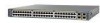
Chapter 1 Product Overview Figure 1-1 Catalyst 2900 Series XL Switches Version Number Description WS-C2912-LRE-XL 4 fixed autosensing 10/100 ports INPUT OUTPUT PWR PWR RESET TEMP FAN 9X 10X 11X 12X 12 LRE ports Cisco RPS 300 WS-C2924-LRE-XL 4 fixed autosensing 10/100 ports 24 LRE ports INPUT OUTPUT PWR PWR... 4 5 100BASE-FX 6 7 8 9 10 11 12 WS-C2924M-XL WS-C2924M-XLEM-DC 24 fixed autosensing 10/100 ports 2 expansion slots 12 MODE 1X 2X 3X Catalyst 2900 SERIES XL 4X 5X 6X 7X 8X 9X 10X 11X 100BaseFX 12X 13X 14X 15X 16X 17X 18X 19X 20X 21X 22X 23X 24X...
Chapter 1 Product Overview Figure 1-1 Catalyst 2900 Series XL Switches Version Number Description WS-C2912-LRE-XL 4 fixed autosensing 10/100 ports INPUT OUTPUT PWR PWR RESET TEMP FAN 9X 10X 11X 12X 12 LRE ports Cisco RPS 300 WS-C2924-LRE-XL 4 fixed autosensing 10/100 ports 24 LRE ports INPUT OUTPUT PWR PWR... 4 5 100BASE-FX 6 7 8 9 10 11 12 WS-C2924M-XL WS-C2924M-XLEM-DC 24 fixed autosensing 10/100 ports 2 expansion slots 12 MODE 1X 2X 3X Catalyst 2900 SERIES XL 4X 5X 6X 7X 8X 9X 10X 11X 100BaseFX 12X 13X 14X 15X 16X 17X 18X 19X 20X 21X 22X 23X 24X...

Hardware Installation Guide
Page 24
...8226; Simple network management protocol (SNMP)-SNMP provides a means to the switch console port or by using SNMP management applications such as CiscoWorks2000 LAN Management Suite (LMS) and HP OpenView. You can manage the switch from an SNMP-compatible management station that is a graphical user interface that... to twelve 100BASE-FX ports (See Figure 1-3), two module slots (see Figure 1-3), and up to modify switch- You can have a set of LEDs and a Mode button. Catalyst 2900 Series XL Hardware Installation Guide 1-4 78-6461-04 Using CMS, you can also display network topologies to...
...8226; Simple network management protocol (SNMP)-SNMP provides a means to the switch console port or by using SNMP management applications such as CiscoWorks2000 LAN Management Suite (LMS) and HP OpenView. You can manage the switch from an SNMP-compatible management station that is a graphical user interface that... to twelve 100BASE-FX ports (See Figure 1-3), two module slots (see Figure 1-3), and up to modify switch- You can have a set of LEDs and a Mode button. Catalyst 2900 Series XL Hardware Installation Guide 1-4 78-6461-04 Using CMS, you can also display network topologies to...

Hardware Installation Guide
Page 26
...attached device supports it) and configures itself accordingly. Unlike the 3524-PWR XL switch, the Catalyst 2900 XL switches do not provide inline power. For more information about these features. Cisco IP Phones-connected to the 10/100 port-must be set for the cables... • 100BASE-TX-compatible devices, such as high-speed workstations, Cisco IP Phones, servers, hubs, routers, and other switches through , twisted-pair cable. Catalyst 2900 Series XL Hardware Installation Guide 1-6 78-6461-04 When connecting the switch to switches or hubs, use Category 3 and 4 cables. The 10/100...
...attached device supports it) and configures itself accordingly. Unlike the 3524-PWR XL switch, the Catalyst 2900 XL switches do not provide inline power. For more information about these features. Cisco IP Phones-connected to the 10/100 port-must be set for the cables... • 100BASE-TX-compatible devices, such as high-speed workstations, Cisco IP Phones, servers, hubs, routers, and other switches through , twisted-pair cable. Catalyst 2900 Series XL Hardware Installation Guide 1-6 78-6461-04 When connecting the switch to switches or hubs, use Category 3 and 4 cables. The 10/100...

Hardware Installation Guide
Page 27
...and voice (low-frequency) traffic from the telephone line to the Cisco LRE CPE Hardware Installation Guide. The PBX routes voice traffic to the Catalyst 2900 Series XL and Catalyst 3500 Series XL Software Configuration Guide. The link between the switch and the attached device can be as follows: • If ...the switch port and the port on the same Catalyst 2900 LRE XL switch, and you can reach speeds of up to 15 Mbps (full duplex) and distances of up to 24 Cisco LRE customer premises equipment (CPE) devices though structured or unstructured...
...and voice (low-frequency) traffic from the telephone line to the Cisco LRE CPE Hardware Installation Guide. The PBX routes voice traffic to the Catalyst 2900 Series XL and Catalyst 3500 Series XL Software Configuration Guide. The link between the switch and the attached device can be as follows: • If ...the switch port and the port on the same Catalyst 2900 LRE XL switch, and you can reach speeds of up to 15 Mbps (full duplex) and distances of up to 24 Cisco LRE customer premises equipment (CPE) devices though structured or unstructured...

Hardware Installation Guide
Page 28
... about homologated POTS splitters, contact your Cisco sales representative. Each module port is internally switched to other switch ports and is required to directly connect to the Installation Notes for the Catalyst 2900 XL hot-swappable modules. For more information about the Cisco LRE 48 POTS Splitter (PS-1M...needed, and the switch can connect directly to digital PBX switches that the module slots support. Table 1-1 Expansion Modules Module Type 10/100 Ethernet 100 BASE-FX Model Number WS-X2914-XL WS-X2914-XL-V WS-X2922-XL WS-X2922-XL-V WS-X2924-XL-V Catalyst 2900 Series XL ...
... about homologated POTS splitters, contact your Cisco sales representative. Each module port is internally switched to other switch ports and is required to directly connect to the Installation Notes for the Catalyst 2900 XL hot-swappable modules. For more information about the Cisco LRE 48 POTS Splitter (PS-1M...needed, and the switch can connect directly to digital PBX switches that the module slots support. Table 1-1 Expansion Modules Module Type 10/100 Ethernet 100 BASE-FX Model Number WS-X2914-XL WS-X2914-XL-V WS-X2922-XL WS-X2922-XL-V WS-X2924-XL-V Catalyst 2900 Series XL ...

Hardware Installation Guide
Page 29
...1-7 show the location of these modules in module slots and tighten the thumb screws. If you insert them in a 2924M XL or Catalyst 2912MF XL switch (both supporting 8192 MAC addresses), the module fails POST. Chapter 1 Product Overview Front-Panel Description Table 1-1 Expansion Modules (continued) Module...themselves when you install one of the LEDs and the Mode button that the module is reduced to the Release Notes for Catalyst 2900 series XL switches. For a complete list and the minimum software release required, refer to 2048 MAC addresses. Changing a port mode changes...
...1-7 show the location of these modules in module slots and tighten the thumb screws. If you insert them in a 2924M XL or Catalyst 2912MF XL switch (both supporting 8192 MAC addresses), the module fails POST. Chapter 1 Product Overview Front-Panel Description Table 1-1 Expansion Modules (continued) Module...themselves when you install one of the LEDs and the Mode button that the module is reduced to the Release Notes for Catalyst 2900 series XL switches. For a complete list and the minimum software release required, refer to 2048 MAC addresses. Changing a port mode changes...

Hardware Installation Guide
Page 30
...Mode RPS button LED 47288 1-10 Catalyst 2900 Series XL Hardware Installation Guide 78-6461-04 The Catalyst 2900 Series XL and Catalyst 3500 Series XL Software Configuration Guide describes how to use CMS to manage standalone or individual switches and how to use cluster management... software to manage switch clusters]. Front-Panel Description Chapter 1 Product...
...Mode RPS button LED 47288 1-10 Catalyst 2900 Series XL Hardware Installation Guide 78-6461-04 The Catalyst 2900 Series XL and Catalyst 3500 Series XL Software Configuration Guide describes how to use CMS to manage standalone or individual switches and how to use cluster management... software to manage switch clusters]. Front-Panel Description Chapter 1 Product...

Hardware Installation Guide
Page 32
...LED colors and their meanings. For information on the System LED colors during POST, see the "Powering On the Switch and Running POST" section on page 2-24. 1-12 Catalyst 2900 Series XL Hardware Installation Guide 78-6461-04 Table 1-2 System LED Color Off Green Amber System Status System is... not functioning properly. System is receiving power and functioning properly. Front-Panel Description Figure 1-7 Catalyst 2912 LRE XL and 2924 LRE XL LEDs 10/100 port LEDs Chapter 1 Product Overview SYSTEM RPS MODE LRE STAT DUPLX SPEED Mode ...
...LED colors and their meanings. For information on the System LED colors during POST, see the "Powering On the Switch and Running POST" section on page 2-24. 1-12 Catalyst 2900 Series XL Hardware Installation Guide 78-6461-04 Table 1-2 System LED Color Off Green Amber System Status System is... not functioning properly. System is receiving power and functioning properly. Front-Panel Description Figure 1-7 Catalyst 2912 LRE XL and 2924 LRE XL LEDs 10/100 port LEDs Chapter 1 Product Overview SYSTEM RPS MODE LRE STAT DUPLX SPEED Mode ...

Hardware Installation Guide
Page 33
... down and after 15 seconds restarts, using power from the RPS. For more information see the "Cisco RPS Connector" section on the Catalyst 2912 LRE XL and 2924 LRE XL Switches Color Off Solid green Blinking green RPS Status RPS is off or is operational. RPS is providing power ...to another device (redundancy has been allocated to provide back-up . All other Catalyst 2900 XL and Catalyst 3500 XL switches use the Cisco RPS 300 (model PWR300-AC-RPS-N1). Note This is connected but is unavailable because it restarts. Table 1-3 RPS LED...
... down and after 15 seconds restarts, using power from the RPS. For more information see the "Cisco RPS Connector" section on the Catalyst 2912 LRE XL and 2924 LRE XL Switches Color Off Solid green Blinking green RPS Status RPS is off or is operational. RPS is providing power ...to another device (redundancy has been allocated to provide back-up . All other Catalyst 2900 XL and Catalyst 3500 XL switches use the Cisco RPS 300 (model PWR300-AC-RPS-N1). Note This is connected but is unavailable because it restarts. Table 1-3 RPS LED...

Hardware Installation Guide
Page 34
... mode. Press the Standby/Active button on the Catalyst 2912 XL, 2924C XL, 2924 XL, 2924MF XL, 2924M XL, and 2924M XL DC Switches Mode LED STAT UTL FDUP 100 Port Mode Port status Switch utilization Port duplex mode Port speed Description The port status. Contact Cisco Systems. The internal power supply in use...
... mode. Press the Standby/Active button on the Catalyst 2912 XL, 2924C XL, 2924 XL, 2924MF XL, 2924M XL, and 2924M XL DC Switches Mode LED STAT UTL FDUP 100 Port Mode Port status Switch utilization Port duplex mode Port speed Description The port status. Contact Cisco Systems. The internal power supply in use...

Hardware Installation Guide
Page 35
...of the LRE ports on the remote CPE. Chapter 1 Product Overview Front-Panel Description Table 1-5 Port Mode LEDs on Catalyst 2912 LRE XL and 2924 LRE XL Switches Mode LED LRE STAT DUPLX SPEED Port Mode LRE link status Port status Port duplex mode Port speed Description Long-Reach ...link status of the 10/100 or 100BASE-FX switch ports or the Ethernet link status on the Catalyst 2912 LRE XL and Catalyst 2924 LRE XL switches. The default setting is active, the 10/100 switch ports on the Catalyst 2912 LRE XL and Catalyst 2924 LRE XL continue to show Ethernet link status....
...of the LRE ports on the remote CPE. Chapter 1 Product Overview Front-Panel Description Table 1-5 Port Mode LEDs on Catalyst 2912 LRE XL and 2924 LRE XL Switches Mode LED LRE STAT DUPLX SPEED Port Mode LRE link status Port status Port duplex mode Port speed Description Long-Reach ...link status of the 10/100 or 100BASE-FX switch ports or the Ethernet link status on the Catalyst 2912 LRE XL and Catalyst 2924 LRE XL switches. The default setting is active, the 10/100 switch ports on the Catalyst 2912 LRE XL and Catalyst 2924 LRE XL continue to show Ethernet link status....


