
Hardware Installation Guide
Page 2
...You can radiate radio-frequency energy and, if not installed and used in the U.S. CCIP, the Cisco Powered Network mark, the Cisco Systems Verified logo, Cisco Unity, Fast Step, Follow Me Browsing, FormShare, Internet Quotient, iQ Breakthrough, iQ Expertise, iQ ...radiate radio-frequency energy. The Cisco implementation of Cisco Systems, Inc.; and Aironet, ASIST, BPX, Catalyst, CCDA, CCDP, CCIE, CCNA, CCNP, Cisco, the Cisco Certified Internetwork Expert logo, Cisco IOS, the Cisco IOS logo, Cisco Press, Cisco Systems, Cisco Systems Capital, the Cisco Systems logo, Empowering the Internet...
...You can radiate radio-frequency energy and, if not installed and used in the U.S. CCIP, the Cisco Powered Network mark, the Cisco Systems Verified logo, Cisco Unity, Fast Step, Follow Me Browsing, FormShare, Internet Quotient, iQ Breakthrough, iQ Expertise, iQ ...radiate radio-frequency energy. The Cisco implementation of Cisco Systems, Inc.; and Aironet, ASIST, BPX, Catalyst, CCDA, CCDP, CCIE, CCNA, CCNP, Cisco, the Cisco Certified Internetwork Expert logo, Cisco IOS, the Cisco IOS logo, Cisco Press, Cisco Systems, Cisco Systems Capital, the Cisco Systems logo, Empowering the Internet...

Hardware Installation Guide
Page 6
... Description 1-19 Power Connectors 1-21 Internal Power Supply Connector 1-21 DC Power Connector 1-21 Cisco RPS Connector 1-22... Console Port 1-23 2 C H A P T E R Installation 2-1 Preparing for Installation 2-1 Warnings 2-1 EMC Regulatory Statements 2-4 U.S.A. 2-4 Taiwan 2-4 Japan 2-5 Korea 2-5 Hungary 2-6 Installation Guidelines 2-6 Verifying Package Contents 2-7 Installing the Switch on a Table or Shelf 2-9 Installing the Switch in a Rack 2-9 Removing Screws from the Switch 2-11 Attaching the Brackets to a Catalyst...
... Description 1-19 Power Connectors 1-21 Internal Power Supply Connector 1-21 DC Power Connector 1-21 Cisco RPS Connector 1-22... Console Port 1-23 2 C H A P T E R Installation 2-1 Preparing for Installation 2-1 Warnings 2-1 EMC Regulatory Statements 2-4 U.S.A. 2-4 Taiwan 2-4 Japan 2-5 Korea 2-5 Hungary 2-6 Installation Guidelines 2-6 Verifying Package Contents 2-7 Installing the Switch on a Table or Shelf 2-9 Installing the Switch in a Rack 2-9 Removing Screws from the Switch 2-11 Attaching the Brackets to a Catalyst...

Hardware Installation Guide
Page 7
...the Optional Cable Guide 2-19 Installing the Switch on a Wall 2-20 Attaching the Brackets to the Switch 2-21 Mounting the Switch to a Wall 2-22 Powering On the Switch and Running POST 2-24 Connecting to DC Power 2-25 Preparing for Installation 2-25 Grounding the Switch 2-26 Wiring the DC-Input Power Source 2-29 Connecting to a 10/100... Module POST Failures 3-2 Diagnosing Problems 3-3 Technical Specifications A-1 Connectors and Cable Specifications B-1 Connector Specifications B-1 10/100 Ports B-1 100BASE-FX Ports B-2 Contents 78-6461-04 Catalyst 2900 Series XL Hardware Installation Guide vii
...the Optional Cable Guide 2-19 Installing the Switch on a Wall 2-20 Attaching the Brackets to the Switch 2-21 Mounting the Switch to a Wall 2-22 Powering On the Switch and Running POST 2-24 Connecting to DC Power 2-25 Preparing for Installation 2-25 Grounding the Switch 2-26 Wiring the DC-Input Power Source 2-29 Connecting to a 10/100... Module POST Failures 3-2 Diagnosing Problems 3-3 Technical Specifications A-1 Connectors and Cable Specifications B-1 Connector Specifications B-1 10/100 Ports B-1 100BASE-FX Ports B-2 Contents 78-6461-04 Catalyst 2900 Series XL Hardware Installation Guide vii

Hardware Installation Guide
Page 8
... Identifying a Rollover Cable B-6 Connecting to a PC B-6 Connecting to a Terminal B-7 Translated Safety Warnings C-1 Attaching the Cisco RPS (model PWR600-AC-RPS) C-1 Attaching the Cisco RPS (model PWR300-AC-RPS-N1) C-2 Qualified Personnel Warning C-3 Installation Warning C-4 Jewelry Removal Warning C-5 Stacking the ... TN Power Warning C-10 Ground Connection Warning C-11 Circuit Breaker (15A) Warning C-12 Grounded Equipment Warning C-14 Supply Circuit Warning C-15 Voltage Warning C-16 Power Supply Warning C-17 Lightning Activity Warning C-19 Product Disposal Warning C-21 Catalyst 2900 Series...
... Identifying a Rollover Cable B-6 Connecting to a PC B-6 Connecting to a Terminal B-7 Translated Safety Warnings C-1 Attaching the Cisco RPS (model PWR600-AC-RPS) C-1 Attaching the Cisco RPS (model PWR300-AC-RPS-N1) C-2 Qualified Personnel Warning C-3 Installation Warning C-4 Jewelry Removal Warning C-5 Stacking the ... TN Power Warning C-10 Ground Connection Warning C-11 Circuit Breaker (15A) Warning C-12 Grounded Equipment Warning C-14 Supply Circuit Warning C-15 Voltage Warning C-16 Power Supply Warning C-17 Lightning Activity Warning C-19 Product Disposal Warning C-21 Catalyst 2900 Series...

Hardware Installation Guide
Page 9
INDEX Class 1 Laser Product Warning C-22 Laser Beam Exposure Warning C-23 No On/Off Switch Warning C-24 Chassis Warning-Rack-Mounting and Servicing C-25 Reinforced Insulation Warning C-29 LAN Connections Only Warning C-30 No Field-Replaceable Units Warning C-31 ...Source Warning C-33 Restricted Access Warning C-34 Shielded Ethernet Cables Warning C-35 Grounded Equipment Warning C-36 Ground Connection Warning C-37 Qualified Personnel Warning C-38 DC Power Disconnection Warning C-39 Exposed Wire Lead Warning C-41 Contents 78-6461-04 Catalyst 2900 Series XL Hardware Installation Guide ix
INDEX Class 1 Laser Product Warning C-22 Laser Beam Exposure Warning C-23 No On/Off Switch Warning C-24 Chassis Warning-Rack-Mounting and Servicing C-25 Reinforced Insulation Warning C-29 LAN Connections Only Warning C-30 No Field-Replaceable Units Warning C-31 ...Source Warning C-33 Restricted Access Warning C-34 Shielded Ethernet Cables Warning C-35 Grounded Equipment Warning C-36 Ground Connection Warning C-37 Qualified Personnel Warning C-38 DC Power Disconnection Warning C-39 Exposed Wire Lead Warning C-41 Contents 78-6461-04 Catalyst 2900 Series XL Hardware Installation Guide ix

Hardware Installation Guide
Page 18
...find information about Cisco and our networking solutions, xviii Catalyst 2900 Series XL Hardware Installation Guide 78-6461-04 You can mail your comments to the following address: Cisco Systems, Inc. Otherwise, you can e-mail your comments to bug-doc@cisco.com. For Cisco.com registered ...using the product-specific CD and you are connected to display the survey. To submit your comments. Cisco.com Cisco.com is a powerful, easy-to the Cisco documentation group. Cisco.com provides a broad range of interactive, networked services that you wish to help customers and partners ...
...find information about Cisco and our networking solutions, xviii Catalyst 2900 Series XL Hardware Installation Guide 78-6461-04 You can mail your comments to the following address: Cisco Systems, Inc. Otherwise, you can e-mail your comments to bug-doc@cisco.com. For Cisco.com registered ...using the product-specific CD and you are connected to display the survey. To submit your comments. Cisco.com Cisco.com is a powerful, easy-to the Cisco documentation group. Cisco.com provides a broad range of interactive, networked services that you wish to help customers and partners ...

Hardware Installation Guide
Page 22
... XL DC switch, a direct current (DC) power converter • On the Catalyst 2912 LRE XL and 2924 LRE XL switches, up to 24 LRE ports through one RJ-21 connector and hot swapping capability with the Cisco LRE customer premises equipment (CPE) devices • Supports up to 2048 MAC addresses on the Catalyst 2924 XL, 2924C...
... XL DC switch, a direct current (DC) power converter • On the Catalyst 2912 LRE XL and 2924 LRE XL switches, up to 24 LRE ports through one RJ-21 connector and hot swapping capability with the Cisco LRE customer premises equipment (CPE) devices • Supports up to 2048 MAC addresses on the Catalyst 2924 XL, 2924C...

Hardware Installation Guide
Page 26
... to operate in Appendix B, "Connectors and Cable Specifications." When connecting the switch to workstations, servers, routers, and Cisco IP Phones, be connected to switches or hubs, use Category 3 and 4 cables. Catalyst 2900 Series XL Hardware Installation Guide 1-6 78-6461-04 The 10/100 ...device also supports autonegotiation, the switch port negotiates the best connection (that is, the fastest line speed that the cable is required for Cisco IP Phones and per-port priority override. Unlike the 3524-PWR XL switch, the Catalyst 2900 XL switches do not provide inline power.
... to operate in Appendix B, "Connectors and Cable Specifications." When connecting the switch to workstations, servers, routers, and Cisco IP Phones, be connected to switches or hubs, use Category 3 and 4 cables. Catalyst 2900 Series XL Hardware Installation Guide 1-6 78-6461-04 The 10/100 ...device also supports autonegotiation, the switch port negotiates the best connection (that is, the fastest line speed that the cable is required for Cisco IP Phones and per-port priority override. Unlike the 3524-PWR XL switch, the Catalyst 2900 XL switches do not provide inline power.

Hardware Installation Guide
Page 27
... voice traffic to LRE ports on the same Catalyst 2900 LRE XL switch, and you can hot swap the CPE devices without powering down the switch or disrupting the other telephone services are configured for full-duplex operation, the connection can connect Cisco 575 LRE CPE and Cisco 585 LRE CPE devices to private telephone networks...
... voice traffic to LRE ports on the same Catalyst 2900 LRE XL switch, and you can hot swap the CPE devices without powering down the switch or disrupting the other telephone services are configured for full-duplex operation, the connection can connect Cisco 575 LRE CPE and Cisco 585 LRE CPE devices to private telephone networks...

Hardware Installation Guide
Page 29
...XL ATM WS-X2971-XL WS-X2972-XL WS-X2951-XL WS-X2961-XL 1. A power-on expansion modules for the Catalyst 2900 Series XL and Catalyst 3500 Series XL Switches. After the restart, the switch address capacity is working properly before it starts forwarding packets. Figure 1-5, Figure 1-6, and ...you insert them in a 2924M XL or Catalyst 2912MF XL switch (both supporting 8192 MAC addresses), the module fails POST. If you use the switch LEDs to 2048 MAC addresses. Refer to the Release Notes for Catalyst 2900 series XL switches. Catalyst 2900 Series XL Hardware Installation Guide 1-9 ...
...XL ATM WS-X2971-XL WS-X2972-XL WS-X2951-XL WS-X2961-XL 1. A power-on expansion modules for the Catalyst 2900 Series XL and Catalyst 3500 Series XL Switches. After the restart, the switch address capacity is working properly before it starts forwarding packets. Figure 1-5, Figure 1-6, and ...you insert them in a 2924M XL or Catalyst 2912MF XL switch (both supporting 8192 MAC addresses), the module fails POST. If you use the switch LEDs to 2048 MAC addresses. Refer to the Release Notes for Catalyst 2900 series XL switches. Catalyst 2900 Series XL Hardware Installation Guide 1-9 ...

Hardware Installation Guide
Page 32
Table 1-2 lists the LED colors and their meanings. For information on the System LED colors during POST, see the "Powering On the Switch and Running POST" section on page 2-24. 1-12 Catalyst 2900 Series XL Hardware Installation Guide 78-6461-04 Table 1-2 System LED Color Off Green Amber System Status System is operating normally...
Table 1-2 lists the LED colors and their meanings. For information on the System LED colors during POST, see the "Powering On the Switch and Running POST" section on page 2-24. 1-12 Catalyst 2900 Series XL Hardware Installation Guide 78-6461-04 Table 1-2 System LED Color Off Green Amber System Status System is operating normally...

Hardware Installation Guide
Page 33
... puts it restarts. Pressing the Mode button on page 1-22. All other Catalyst 2900 XL and Catalyst 3500 XL switches use the Cisco RPS 300 (model PWR300-AC-RPS-N1). If the switch power supply fails, the switch powers down and after 15 seconds restarts, using power from the RPS. Chapter 1 Product Overview Front-Panel Description RPS LED The...
... puts it restarts. Pressing the Mode button on page 1-22. All other Catalyst 2900 XL and Catalyst 3500 XL switches use the Cisco RPS 300 (model PWR300-AC-RPS-N1). If the switch power supply fails, the switch powers down and after 15 seconds restarts, using power from the RPS. Chapter 1 Product Overview Front-Panel Description RPS LED The...

Hardware Installation Guide
Page 34
...mode or in a fault condition. Press the Standby/Active button on the Catalyst 2912 XL, 2924C XL, 2924 XL, 2924MF XL, 2924M XL, and 2924M XL DC Switches Mode LED STAT UTL FDUP 100 Port Mode Port status Switch utilization Port duplex mode Port speed Description The port status. The current ... about the individual ports. If it does not, the RPS fan could have a port LED. Contact Cisco Systems. The internal power supply in use by the switch. (See Figure 1-8.) The port duplex mode: full duplex or half duplex, and default modes: • 10/100 ports: auto • 100BaseFX ports: auto •...
...mode or in a fault condition. Press the Standby/Active button on the Catalyst 2912 XL, 2924C XL, 2924 XL, 2924MF XL, 2924M XL, and 2924M XL DC Switches Mode LED STAT UTL FDUP 100 Port Mode Port status Switch utilization Port duplex mode Port speed Description The port status. The current ... about the individual ports. If it does not, the RPS fan could have a port LED. Contact Cisco Systems. The internal power supply in use by the switch. (See Figure 1-8.) The port duplex mode: full duplex or half duplex, and default modes: • 10/100 ports: auto • 100BaseFX ports: auto •...

Hardware Installation Guide
Page 39
... Chapter 1 Product Overview Rear-Panel Description Module Slot LEDs Module slot LEDs (shown in Figure 1-6) show the status of a Catalyst 2900 XL and Catalyst 2900 LRE XL switches have an AC power connector, an RPS connector, and an RJ-45 console port. (See Figure 1-10 through Figure 1-12.) Figure 1-10... Catalyst 2912 XL, 2924 XL, and 2924C XL Rear Panel Fans 47295 11.000A-/1O2R.75A/AT2I0N50G0-2-8400HV~Z AC power connector +...
... Chapter 1 Product Overview Rear-Panel Description Module Slot LEDs Module slot LEDs (shown in Figure 1-6) show the status of a Catalyst 2900 XL and Catalyst 2900 LRE XL switches have an AC power connector, an RPS connector, and an RJ-45 console port. (See Figure 1-10 through Figure 1-12.) Figure 1-10... Catalyst 2912 XL, 2924 XL, and 2924C XL Rear Panel Fans 47295 11.000A-/1O2R.75A/AT2I0N50G0-2-8400HV~Z AC power connector +...

Hardware Installation Guide
Page 40
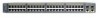
...-45 connector +5DVSCPINEPCPO@IUWF9TIAEES,[email protected] DC INPUT 21.000A-/11R2.0A0AT/2IN050G0--26400HVZ~ 47296 Redundant power system AC power connector connector The rear panel of the Catalyst 2924M XL DC switch has a DC power connector (also referred to as the terminal block header), an RJ-45 console port, and a ground lug. (See...
...-45 connector +5DVSCPINEPCPO@IUWF9TIAEES,[email protected] DC INPUT 21.000A-/11R2.0A0AT/2IN050G0--26400HVZ~ 47296 Redundant power system AC power connector connector The rear panel of the Catalyst 2924M XL DC switch has a DC power connector (also referred to as the terminal block header), an RJ-45 console port, and a ground lug. (See...
Hardware Installation Guide
Page 41
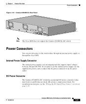
... 74070 CONSOLE BERFEOFREERPOCTOWONEMNRAENCUTAINL G DC INPUT ICNUPRURTE: 3N6T:- 72 4-2A A +- Power Connectors You can provide power to an AC power outlet. DC Power Connector The Catalyst 2924M XL DC switch has an internal DC-power converter. Note The Cisco RPS does not support the Catalyst 2924M XL DC switch. It has dual feeds (A and B) that supports input voltages between 100 and...
... 74070 CONSOLE BERFEOFREERPOCTOWONEMNRAENCUTAINL G DC INPUT ICNUPRURTE: 3N6T:- 72 4-2A A +- Power Connectors You can provide power to an AC power outlet. DC Power Connector The Catalyst 2924M XL DC switch has an internal DC-power converter. Note The Cisco RPS does not support the Catalyst 2924M XL DC switch. It has dual feeds (A and B) that supports input voltages between 100 and...

Hardware Installation Guide
Page 42
... connector at each cable end) to connect four external devices to -72 VDC. The power source is not in the RPS documentation. Cisco RPS Connector Specific Cisco RPS models support specific Catalyst 2900 XL switches: • Cisco RPS 600 (model PWR600-AC-RPS)-supports the Catalyst 2912 XL, 2924C XL, 2924 XL, 2924MF XL, and 2924M XL...
... connector at each cable end) to connect four external devices to -72 VDC. The power source is not in the RPS documentation. Cisco RPS Connector Specific Cisco RPS models support specific Catalyst 2900 XL switches: • Cisco RPS 600 (model PWR600-AC-RPS)-supports the Catalyst 2912 XL, 2924C XL, 2924 XL, 2924MF XL, and 2924M XL...

Hardware Installation Guide
Page 43
...section on page 2-42. 78-6461-04 Catalyst 2900 Series XL Hardware Installation Guide 1-23 Note The RPS can only power one failed device at a time. If more information on the Cisco RPS 300, refer to the Cisco Redundant Power System 300 Hardware Installation Guide. You need ... the RPS automatically stops powering the device. Chapter 1 Product Overview Power Connectors RPS Connector on the Catalyst 2912 LRE and 2924 LRE XL Switches The RPS is resolved. It automatically senses when the power supply of a connected device fails and provides the necessary power to the failed device...
...section on page 2-42. 78-6461-04 Catalyst 2900 Series XL Hardware Installation Guide 1-23 Note The RPS can only power one failed device at a time. If more information on the Cisco RPS 300, refer to the Cisco Redundant Power System 300 Hardware Installation Guide. You need ... the RPS automatically stops powering the device. Chapter 1 Product Overview Power Connectors RPS Connector on the Catalyst 2912 LRE and 2924 LRE XL Switches The RPS is resolved. It automatically senses when the power supply of a connected device fails and provides the necessary power to the failed device...

Hardware Installation Guide
Page 44
Power Connectors Chapter 1 Product Overview 1-24 Catalyst 2900 Series XL Hardware Installation Guide 78-6461-04
Power Connectors Chapter 1 Product Overview 1-24 Catalyst 2900 Series XL Hardware Installation Guide 78-6461-04

Hardware Installation Guide
Page 45
... expansion modules. Installation CH A P T E R 2 This chapter describes how to install your Catalyst 2900 XL switch and interpret the power-on procedures • Connection procedures • Where to go next Note Refer to the Catalyst 2900 Series XL Modules Installation Guide and the Catalyst 2900 Series XL ATM Modules Installation and Configuration Guide for Installation Warnings...
... expansion modules. Installation CH A P T E R 2 This chapter describes how to install your Catalyst 2900 XL switch and interpret the power-on procedures • Connection procedures • Where to go next Note Refer to the Catalyst 2900 Series XL Modules Installation Guide and the Catalyst 2900 Series XL ATM Modules Installation and Configuration Guide for Installation Warnings...
