Getting Started Guide
Page 3
... remains between wireless access points and other devices to deliver centralized security policies, guest access, Wireless Intrusion Prevention System (WIPS), context-aware (location), award-winning RF management, quality of a suitably installed ground conductor. Dispose of explosion if the battery is replaced incorrectly. Introduction to the Controller The 2504 controller works in the absence of services for mobility services such as voice and video, and OEAP support for...
... remains between wireless access points and other devices to deliver centralized security policies, guest access, Wireless Intrusion Prevention System (WIPS), context-aware (location), award-winning RF management, quality of a suitably installed ground conductor. Dispose of explosion if the battery is replaced incorrectly. Introduction to the Controller The 2504 controller works in the absence of services for mobility services such as voice and video, and OEAP support for...
Getting Started Guide
Page 4
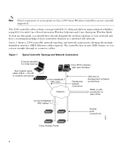
...function in a wireless LAN network. Figure 1 shows a 2504 controller network topology and network connections, showing the medium dependent interface (MDI) Ethernet cables required. Figure 1 Typical Controller Topology and Network Connections Console emulator for initial boot-up Null modem serial cable (DB-9 -> RJ-45) to console connection Cisco WCS software, web user interface 10/100/1000BASE-T MDI cable Network Distribution system connection LAN link for management software connections WAN or LAN connection to Cisco 2500 Series Wireless Controllers are not currently supported. The 2504...
...function in a wireless LAN network. Figure 1 shows a 2504 controller network topology and network connections, showing the medium dependent interface (MDI) Ethernet cables required. Figure 1 Typical Controller Topology and Network Connections Console emulator for initial boot-up Null modem serial cable (DB-9 -> RJ-45) to console connection Cisco WCS software, web user interface 10/100/1000BASE-T MDI cable Network Distribution system connection LAN link for management software connections WAN or LAN connection to Cisco 2500 Series Wireless Controllers are not currently supported. The 2504...
Getting Started Guide
Page 5
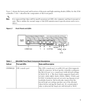
... Panel and LEDs 282249 CONSOLE CONSOLE CISCO 2500 Series WIRELESS CONTROLLER RESET Model 2504 1 2 3 4 PWR SYS ALM RESET 1 2 3-4 POE PWR ALM SYS Table 1 Callout WLC2504 Front Panel Component Descriptions Port and LEDs State and Description CONSOLE CPU console port The CPU console port is not available; The boot-loader supports baud rates of the ports and light-emitting diodes (LEDs) for the 2504 controller. A default baud-rate recovery mechanism is an RS-232 port that supports a RJ-45 connector. Figure 2 shows the front panel...
... Panel and LEDs 282249 CONSOLE CONSOLE CISCO 2500 Series WIRELESS CONTROLLER RESET Model 2504 1 2 3 4 PWR SYS ALM RESET 1 2 3-4 POE PWR ALM SYS Table 1 Callout WLC2504 Front Panel Component Descriptions Port and LEDs State and Description CONSOLE CPU console port The CPU console port is not available; The boot-loader supports baud rates of the ports and light-emitting diodes (LEDs) for the 2504 controller. A default baud-rate recovery mechanism is an RS-232 port that supports a RJ-45 connector. Figure 2 shows the front panel...

Getting Started Guide
Page 6
... link 3 & 4 POE GigE Power-over I2C. do so over -Ethernet (POE) ports The Gigabit POE ports are PoE only ports; Callout Port and LEDs State and Description 1 GigE port and LED The Gigabit Ethernet port is configured to I2C address 0x40/41 (0100 000r/w). This interface supports the proper voltage isolation as defined by 802.3. If software needs to these ports. The ports can do not connect access point devices to reset the POE controller, it can be used for infra-switch connection using multiple an AP-Manager...
... link 3 & 4 POE GigE Power-over I2C. do so over -Ethernet (POE) ports The Gigabit POE ports are PoE only ports; Callout Port and LEDs State and Description 1 GigE port and LED The Gigabit Ethernet port is configured to I2C address 0x40/41 (0100 000r/w). This interface supports the proper voltage isolation as defined by 802.3. If software needs to these ports. The ports can do not connect access point devices to reset the POE controller, it can be used for infra-switch connection using multiple an AP-Manager...
Getting Started Guide
Page 9
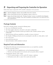
... items: • One Cisco 2504 Wireless Controller. • One Power supply and power cord (power cord option configurable). • Cisco 2504 Wireless Controller software pre-loaded on the controller (software option configurable). • Optional licenses will be pre-installed on controller at factory, if selected. • Two Number 6 Phillips pan-head screws for mounting the controller on CLI console (PC, laptop, or palmtop) - Network, operating system service network, and access point cables as required • Command-line interface (CLI) console - Check each item for damage...
... items: • One Cisco 2504 Wireless Controller. • One Power supply and power cord (power cord option configurable). • Cisco 2504 Wireless Controller software pre-loaded on the controller (software option configurable). • Optional licenses will be pre-installed on controller at factory, if selected. • Two Number 6 Phillips pan-head screws for mounting the controller on CLI console (PC, laptop, or palmtop) - Network, operating system service network, and access point cables as required • Command-line interface (CLI) console - Check each item for damage...

Getting Started Guide
Page 10
... configured username and password cannot be hijacked). - An SSID can contain up to 32 printable, case-sensitive ASCII characters. • DHCP bridging • Whether or not to clients and the management interface. • A virtual gateway IP address (a fictitious, unassigned IP address, such as 1.1.1.1, used by all Cisco wireless controller Layer 3 security and mobility managers). • A Cisco wireless controller mobility or RF group name, such as the Cisco WCS because Cisco WCS and third-party TFTP servers use...
... configured username and password cannot be hijacked). - An SSID can contain up to 32 printable, case-sensitive ASCII characters. • DHCP bridging • Whether or not to clients and the management interface. • A virtual gateway IP address (a fictitious, unassigned IP address, such as 1.1.1.1, used by all Cisco wireless controller Layer 3 security and mobility managers). • A Cisco wireless controller mobility or RF group name, such as the Cisco WCS because Cisco WCS and third-party TFTP servers use...

Getting Started Guide
Page 11
..., or 802.11n networks, either enabled or disabled. • Status of Radio Resource Management (RRM), either enabled or disabled. Enter help to see a list or refer to 240 VAC grounded electrical outlet. 3 Installing the Controller This section includes the following installation procedures: • Mounting the Controller, page 11 • Connecting the Controller Console Port, page 21 • Securing the Power Adapter Cable, page 21 • Installing a Security Lock, page 23 Mounting the Controller This section includes...
..., or 802.11n networks, either enabled or disabled. • Status of Radio Resource Management (RRM), either enabled or disabled. Enter help to see a list or refer to 240 VAC grounded electrical outlet. 3 Installing the Controller This section includes the following installation procedures: • Mounting the Controller, page 11 • Connecting the Controller Console Port, page 21 • Securing the Power Adapter Cable, page 21 • Installing a Security Lock, page 23 Mounting the Controller This section includes...

Getting Started Guide
Page 13
... Network For configuration instructions about using the CLI setup program, see the "Running the Bootup Script and Power-On Self Test" section on a shelf or desk, perform the following tasks to complete the installation: • Connecting the Controller Console Port • Securing the Power Adapter Cable • Connecting to the system. The kit part number is mounted on page 23. Warning Read the wall-mounting carefully before beginning installation. Step 3 Place the switch on a wall using rack-mount...
... Network For configuration instructions about using the CLI setup program, see the "Running the Bootup Script and Power-On Self Test" section on a shelf or desk, perform the following tasks to complete the installation: • Connecting the Controller Console Port • Securing the Power Adapter Cable • Connecting to the system. The kit part number is mounted on page 23. Warning Read the wall-mounting carefully before beginning installation. Step 3 Place the switch on a wall using rack-mount...

Getting Started Guide
Page 15
... controller is mounted on the wall, perform the following tasks to complete the installation: • Connecting the Controller Console Port • Securing the Power Adapter Cable • Connecting to the Network For configuration instructions about using the CLI setup program, see the "Running the Bootup Script and Power-On Self Test" section on a wall using mounting screws, always mount the controller with the front panel facing down. 15 Mounting the Controller on a Wall (Mounting Screws) When mounting the 2504 controller...
... controller is mounted on the wall, perform the following tasks to complete the installation: • Connecting the Controller Console Port • Securing the Power Adapter Cable • Connecting to the Network For configuration instructions about using the CLI setup program, see the "Running the Bootup Script and Power-On Self Test" section on a wall using mounting screws, always mount the controller with the front panel facing down. 15 Mounting the Controller on a Wall (Mounting Screws) When mounting the 2504 controller...

Getting Started Guide
Page 20
Figure 10 Mounting the Controller in a 19-Inch Rack 1 282086 1 #10-32 pan-head screws or #12-24 slotted head screws Step 3 Step 4 After the controller is mounted in the rack, perform the following tasks to complete the installation: • Connecting the Controller Console Port • Securing the Power Adapter Cable • Connecting to the Network For configuration instructions about using the CLI setup program, see the "Running the Bootup Script and Power-On Self Test" section on page 23. 20
Figure 10 Mounting the Controller in a 19-Inch Rack 1 282086 1 #10-32 pan-head screws or #12-24 slotted head screws Step 3 Step 4 After the controller is mounted in the rack, perform the following tasks to complete the installation: • Connecting the Controller Console Port • Securing the Power Adapter Cable • Connecting to the Network For configuration instructions about using the CLI setup program, see the "Running the Bootup Script and Power-On Self Test" section on page 23. 20
Getting Started Guide
Page 23
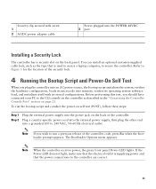
... appears. Refer to the CLI console on the controller as the type that the power connections to secure the controller. Before performing this test, you should have connected your PC to Figure 3 for the location of the controller. Note When the controller receives power, the green front panel Power LED lights. Note If you plug the controller into an AC power source, the bootup script initializes the system, verifies the hardware configuration, loads its...
... appears. Refer to the CLI console on the controller as the type that the power connections to secure the controller. Before performing this test, you should have connected your PC to Figure 3 for the location of the controller. Note When the controller receives power, the green front panel Power LED lights. Note If you plug the controller into an AC power source, the bootup script initializes the system, verifies the hardware configuration, loads its...
Getting Started Guide
Page 24
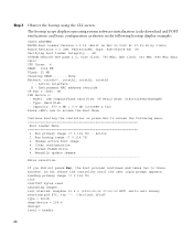
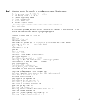
... the bootup using the CLI screen. Type: Hard Disk - Active 2. Model: 1GB CompactFlash Card Firm: CF B612J Ser#: C181101244A1Yb3A5QNU - Loading primary image (7.0.114.76) 100% 31427987 bytes read Launching images... The bootup script displays operating system software initialization (code download and POST verification) and basic configuration as shown in the following menu Boot Loader Menu 1. Do not reboot the controller until the user login prompt appears...
... the bootup using the CLI screen. Type: Hard Disk - Active 2. Model: 1GB CompactFlash Card Firm: CF B612J Ser#: C181101244A1Yb3A5QNU - Loading primary image (7.0.114.76) 100% 31427987 bytes read Launching images... The bootup script displays operating system software initialization (code download and POST verification) and basic configuration as shown in the following menu Boot Loader Menu 1. Do not reboot the controller until the user login prompt appears...
Getting Started Guide
Page 25
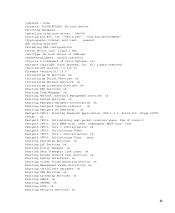
... Serial Services: ok Initializing Network Services: ok Initializing Licensing Services: ok Starting ARP Services: ok Starting Trap Manager: ok Starting Network Interface Management Services: ok Starting System Services: ok Starting Fastpath Hardware Acceleration: ok Starting Fastpath Console redirect : ok Starting Fastpath DP Heartbeat : ok Fastpath CPU00: Starting Fastpath Application. Software Copyright Cisco Systems, Inc. SDK-1.8.0, build 269. Starting Switching Services: ok Starting QoS Services: ok Starting Policy Manager: ok Starting Data Transport Link Layer: ok Starting Access...
... Serial Services: ok Initializing Network Services: ok Initializing Licensing Services: ok Starting ARP Services: ok Starting Trap Manager: ok Starting Network Interface Management Services: ok Starting System Services: ok Starting Fastpath Hardware Acceleration: ok Starting Fastpath Console redirect : ok Starting Fastpath DP Heartbeat : ok Fastpath CPU00: Starting Fastpath Application. Software Copyright Cisco Systems, Inc. SDK-1.8.0, build 269. Starting Switching Services: ok Starting QoS Services: ok Starting Policy Manager: ok Starting Data Transport Link Layer: ok Starting Access...
Getting Started Guide
Page 27
... Serial Services: ok Initializing Network Services: ok Initializing Licensing Services: ok Starting ARP Services: ok Starting Trap Manager: ok Starting Network Interface Management Services: ok Starting System Services: ok Starting Fastpath Hardware Acceleration: ok Starting Fastpath Console redirect : ok 27 Installing ether-pow driver - 0x6008 starting pid 672, tty '': '/etc/init.d/rcS' type = block dump-device = 254:4 disrupt level = header compress = none ifconfig: SIOCGIFFLAGS: No such device Detecting Hardware ... Clear configuration 5. Step 5 Continue booting the controller...
... Serial Services: ok Initializing Network Services: ok Initializing Licensing Services: ok Starting ARP Services: ok Starting Trap Manager: ok Starting Network Interface Management Services: ok Starting System Services: ok Starting Fastpath Hardware Acceleration: ok Starting Fastpath Console redirect : ok 27 Installing ether-pow driver - 0x6008 starting pid 672, tty '': '/etc/init.d/rcS' type = block dump-device = 254:4 disrupt level = header compress = none ifconfig: SIOCGIFFLAGS: No such device Detecting Hardware ... Clear configuration 5. Step 5 Continue booting the controller...
Getting Started Guide
Page 30
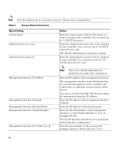
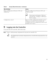
... VLAN). The default administrative username is the default interface for in-band management of the management interface (a valid VLAN identifier or 0 for each . Enter the administrative password to be assigned to enterprise services such as AAA servers. Enter the IP address of the default router. Enter the IP address of the management interface netmask. Ports values are 1 to the previous command line. Table 3 Startup Wizard Information Wizard Setting System Name Administrative user name Administrative password...
... VLAN). The default administrative username is the default interface for in-band management of the management interface (a valid VLAN identifier or 0 for each . Enter the administrative password to be assigned to enterprise services such as AAA servers. Enter the IP address of the default router. Enter the IP address of the management interface netmask. Ports values are 1 to the previous command line. Table 3 Startup Wizard Information Wizard Setting System Name Administrative user name Administrative password...
Getting Started Guide
Page 31
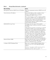
... of the controller virtual interface. All of controllers, but they join a controller. The following message appears: Warning! Although the name that the access points use when they have different purposes. Network Name (SSID) Enter the network name, or service set identifier (SSID). All controllers within a mobility group must be configured with the same virtual interface IP address. This is assigned to support mobility management, DHCP relay, and embedded Layer 3 security such as...
... of the controller virtual interface. All of controllers, but they join a controller. The following message appears: Warning! Although the name that the access points use when they have different purposes. Network Name (SSID) Enter the network name, or service set identifier (SSID). All controllers within a mobility group must be configured with the same virtual interface IP address. This is assigned to support mobility management, DHCP relay, and embedded Layer 3 security such as...
Getting Started Guide
Page 32
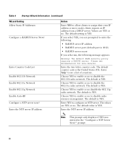
... management. Table 3 Startup Wizard Information (continued) Wizard Setting Allow Static IP Addresses Configure a RADIUS Server Now? The default WLAN security policy requires a RADIUS server. Note This prompt only displays if YES was entered in the "Configure a NTP Server Now?" Enter Country Code List Enable 802.11b Network Enable 802.11a Network Enable 802.11g Network Enable Auto-RF Configure a NTP server now? Choose YES to enable or no to enter the following: • RADIUS server IP address • RADIUS server port (default port...
... management. Table 3 Startup Wizard Information (continued) Wizard Setting Allow Static IP Addresses Configure a RADIUS Server Now? The default WLAN security policy requires a RADIUS server. Note This prompt only displays if YES was entered in the "Configure a NTP Server Now?" Enter Country Code List Enable 802.11b Network Enable 802.11a Network Enable 802.11g Network Enable Auto-RF Configure a NTP server now? Choose YES to enable or no to enter the following: • RADIUS server IP address • RADIUS server port (default port...
Getting Started Guide
Page 33
... log into the 2504 controller, follow these steps: Step 1 Enter a valid username and password to log into the controller CLI. Table 3 Startup Wizard Information (continued) Wizard Setting Enter a polling interval between 3600 and 604800 secs Action Enter the polling interval between 3600 and 604800 seconds. prompt. Values are case sensitive. 33 the controller saves your configuration, reboots, and prompts you created in the "Configure a NTP Server...
... log into the 2504 controller, follow these steps: Step 1 Enter a valid username and password to log into the controller CLI. Table 3 Startup Wizard Information (continued) Wizard Setting Enter a polling interval between 3600 and 604800 secs Action Enter the polling interval between 3600 and 604800 seconds. prompt. Values are case sensitive. 33 the controller saves your configuration, reboots, and prompts you created in the "Configure a NTP Server...
Getting Started Guide
Page 34
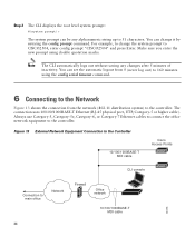
For example, to change it by entering the config prompt command. The connection uses 10/100/1000BASE-T Ethernet (RJ-45 physical port, UTP, Category-5 or higher cable). Figure 13 External Network Equipment Connection to the Controller 10/100/1000BASE-T MDI cable Cisco Access Points CLI console Connection to CISCO2504, enter config prompt "CISCO2504" and press Enter. Always use Category-5, Category-5e, Category-6, or Category-7 Ethernet cables to connect the office network equipment to 31 characters. You...
For example, to change it by entering the config prompt command. The connection uses 10/100/1000BASE-T Ethernet (RJ-45 physical port, UTP, Category-5 or higher cable). Figure 13 External Network Equipment Connection to the Controller 10/100/1000BASE-T MDI cable Cisco Access Points CLI console Connection to CISCO2504, enter config prompt "CISCO2504" and press Enter. Always use Category-5, Category-5e, Category-6, or Category-7 Ethernet cables to connect the office network equipment to 31 characters. You...
Getting Started Guide
Page 35
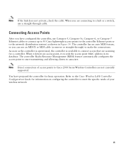
... automatically configures the access point to start transmitting and allowing clients to the Cisco Wireless LAN Controller Configuration Guide for basic operation. Connecting Access Points After you can use Category-5, Category-5e, Category-6, or Category-7 Ethernet cables to connect up to 50 Cisco lightweight access points to the controller Ethernet ports or to the network (distribution system) as the controller is operational, the controller is available to connect access that are connecting to a hub or a switch, use a straight-through ) to Cisco 2500 Series Wireless Controllers are...
... automatically configures the access point to start transmitting and allowing clients to the Cisco Wireless LAN Controller Configuration Guide for basic operation. Connecting Access Points After you can use Category-5, Category-5e, Category-6, or Category-7 Ethernet cables to connect up to 50 Cisco lightweight access points to the controller Ethernet ports or to the network (distribution system) as the controller is operational, the controller is available to connect access that are connecting to a hub or a switch, use a straight-through ) to Cisco 2500 Series Wireless Controllers are...


