Getting Started Guide
Page 3
... Statement 1024 Warning Ultimate disposal of this product should be grounded. The 2504 controller comes with Cisco lightweight access points and the Cisco Wireless Control System (WCS) to provide system-wide wireless LAN functions. Introduction to 240 VAC, ...50-60 Hz, output: 80 W per controller). • Verify the integrity of the Cisco Unified Wireless Network (CUWN), the 2504 controller provides real-time communication between 32 to 104° F (0 to 40°...50 lightweight access points in conjunction with four 4 Gigabit Ethernet ports. 3
... Statement 1024 Warning Ultimate disposal of this product should be grounded. The 2504 controller comes with Cisco lightweight access points and the Cisco Wireless Control System (WCS) to provide system-wide wireless LAN functions. Introduction to 240 VAC, ...50-60 Hz, output: 80 W per controller). • Verify the integrity of the Cisco Unified Wireless Network (CUWN), the 2504 controller provides real-time communication between 32 to 104° F (0 to 40°...50 lightweight access points in conjunction with four 4 Gigabit Ethernet ports. 3
Getting Started Guide
Page 5
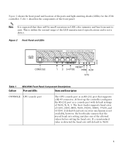
... LED color intensity and hue from unit to 9600. 5 The boot-loader supports baud rates of the ports and light-emitting diodes (LEDs) for the 2504 controller. Figure 2 Front Panel and LEDs 282249 CONSOLE CONSOLE CISCO 2500 Series WIRELESS CONTROLLER RESET Model 2504 1 2 3 4 PWR SYS ALM RESET 1 2 3-4 POE PWR ALM SYS Table...
... LED color intensity and hue from unit to 9600. 5 The boot-loader supports baud rates of the ports and light-emitting diodes (LEDs) for the 2504 controller. Figure 2 Front Panel and LEDs 282249 CONSOLE CONSOLE CISCO 2500 Series WIRELESS CONTROLLER RESET Model 2504 1 2 3 4 PWR SYS ALM RESET 1 2 3-4 POE PWR ALM SYS Table...

Getting Started Guide
Page 6
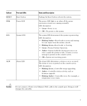
... Blinking Green-Link activity • Off-No link 3 & 4 POE GigE Power-over I2C. do so over -Ethernet (POE) ports The Gigabit POE ports are PoE only ports; The POE controller reset is an RJ-45 connector form-factor. LED description: • Green or Blinking Green-Link activity •... Off-No link 2 GigE port and LED The Gigabit Ethernet port is driven from system reset. This port is designed so that 1500 VAC rms isolation (per the 802.3 specification) is met between chassis ground ...
... Blinking Green-Link activity • Off-No link 3 & 4 POE GigE Power-over I2C. do so over -Ethernet (POE) ports The Gigabit POE ports are PoE only ports; The POE controller reset is an RJ-45 connector form-factor. LED description: • Green or Blinking Green-Link activity •... Off-No link 2 GigE port and LED The Gigabit Ethernet port is driven from system reset. This port is designed so that 1500 VAC rms isolation (per the 802.3 specification) is met between chassis ground ...
Getting Started Guide
Page 7
... System Operation. • Amber-System failed the bootup process or an error caused the system to halt. For example, a temperature error exists. Callout RESET PWR Port and LEDs Reset button Power LED SYS System LED ALM Alarm LED State and Description Pushing the Reset button reboots the system. LED description: •... system The system LED determines if the system is powered up. The power LED light is posted on • Off-No power to the console port. LED description: • Green-Power is on the console screen. The alarm LED determines a status or error occurred.
... System Operation. • Amber-System failed the bootup process or an error caused the system to halt. For example, a temperature error exists. Callout RESET PWR Port and LEDs Reset button Power LED SYS System LED ALM Alarm LED State and Description Pushing the Reset button reboots the system. LED description: •... system The system LED determines if the system is powered up. The power LED light is posted on • Off-No power to the console port. LED description: • Green-Power is on the console screen. The alarm LED determines a status or error occurred.
Getting Started Guide
Page 8
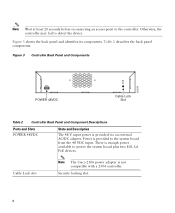
...identifies its components. Security locking slot. 8 Figure 3 Controller Back Panel and Components 282250 POWER 48VDC Cable Lock Slot Table 2 Controller Back Panel and Component Descriptions Ports and Slots POWER 48VDC State and Description The 48 V input power is provided to power the system board plus two 802.3af PoE devices. Note... back panel components. Power is provided via an external AC/DC adapter. There is not compatible with a 2504 controller. Cable Lock slot Note The Cisco 2106 power adapter is enough power available to the system board from the 48 VDC input.
...identifies its components. Security locking slot. 8 Figure 3 Controller Back Panel and Components 282250 POWER 48VDC Cable Lock Slot Table 2 Controller Back Panel and Component Descriptions Ports and Slots POWER 48VDC State and Description The 48 V input power is provided to power the system board plus two 802.3af PoE devices. Note... back panel components. Power is provided via an external AC/DC adapter. There is not compatible with a 2504 controller. Cable Lock slot Note The Cisco 2106 power adapter is enough power available to the system board from the 48 VDC input.

Getting Started Guide
Page 10
...to 32 printable ASCII characters. • An administrative username and password, which can be the same. • A management interface (DS Port or network interface port) IP address, such as 10.40.0.4. • A management interface netmask address, such as 255.255.255.0. • A management ...from your wireless LAN or network administrator: • A system (controller name), such as the Cisco WCS because Cisco WCS and third-party TFTP servers use the same communication port. No is more convenient, but has higher security and works well for downloading operating system software...
...to 32 printable ASCII characters. • An administrative username and password, which can be the same. • A management interface (DS Port or network interface port) IP address, such as 10.40.0.4. • A management interface netmask address, such as 255.255.255.0. • A management ...from your wireless LAN or network administrator: • A system (controller name), such as the Cisco WCS because Cisco WCS and third-party TFTP servers use the same communication port. No is more convenient, but has higher security and works well for downloading operating system software...

Getting Started Guide
Page 11
...Configuration Guide for this installation. Leave at cisco.com. • Status of the 802.11a, 802.11b, 802.11g, or 802.11n networks, either enabled or disabled. • Status of equipment connected to the 10/100/1000 Mb/s Ethernet ports. • Make sure that airflow ...outlet. 3 Installing the Controller This section includes the following installation procedures: • Mounting the Controller, page 11 • Connecting the Controller Console Port, page 21 • Securing the Power Adapter Cable, page 21 • Installing a Security Lock, page 23 Mounting the Controller This section ...
...Configuration Guide for this installation. Leave at cisco.com. • Status of the 802.11a, 802.11b, 802.11g, or 802.11n networks, either enabled or disabled. • Status of equipment connected to the 10/100/1000 Mb/s Ethernet ports. • Make sure that airflow ...outlet. 3 Installing the Controller This section includes the following installation procedures: • Mounting the Controller, page 11 • Connecting the Controller Console Port, page 21 • Securing the Power Adapter Cable, page 21 • Installing a Security Lock, page 23 Mounting the Controller This section ...

Getting Started Guide
Page 13
... After the controller is mounted on a shelf or desk, perform the following tasks to complete the installation: • Connecting the Controller Console Port • Securing the Power Adapter Cable • Connecting to the Network For configuration instructions about using the CLI setup program, see the "...The controller can order a kit with #10-32 flat head screws provided in Figure 5 with 19-inch rack mounting brackets and hardware from Cisco. Step 3 Place the switch on a wall using an optional rack-mount bracket kit that is not included with the controller. Warning Read...
... After the controller is mounted on a shelf or desk, perform the following tasks to complete the installation: • Connecting the Controller Console Port • Securing the Power Adapter Cable • Connecting to the Network For configuration instructions about using the CLI setup program, see the "...The controller can order a kit with #10-32 flat head screws provided in Figure 5 with 19-inch rack mounting brackets and hardware from Cisco. Step 3 Place the switch on a wall using an optional rack-mount bracket kit that is not included with the controller. Warning Read...

Getting Started Guide
Page 15
... mounting screws Step 3 Step 4 After the controller is mounted on the wall, perform the following tasks to complete the installation: • Connecting the Controller Console Port • Securing the Power Adapter Cable • Connecting to the Network For configuration instructions about using the CLI setup program, see the "Running the Bootup...
... mounting screws Step 3 Step 4 After the controller is mounted on the wall, perform the following tasks to complete the installation: • Connecting the Controller Console Port • Securing the Power Adapter Cable • Connecting to the Network For configuration instructions about using the CLI setup program, see the "Running the Bootup...
Getting Started Guide
Page 17
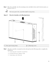
Step 4 Place the controller onto the mounting screws and slide it down ) 2 Mounting screws Step 5 After the controller is mounted ion the wall, perform the following tasks to complete the installation: • Connecting the Controller Console Port • Securing the Power Adapter Cable • Connecting to the Network 17 Figure 8 Place the Controller on the Mounting Screws 282085 2 1 2 1 Front panel (facing down until it lock into place, as shown in Figure 8. Note The front panel of the controller should be facing down.
Step 4 Place the controller onto the mounting screws and slide it down ) 2 Mounting screws Step 5 After the controller is mounted ion the wall, perform the following tasks to complete the installation: • Connecting the Controller Console Port • Securing the Power Adapter Cable • Connecting to the Network 17 Figure 8 Place the Controller on the Mounting Screws 282085 2 1 2 1 Front panel (facing down until it lock into place, as shown in Figure 8. Note The front panel of the controller should be facing down.

Getting Started Guide
Page 20
Figure 10 Mounting the Controller in a 19-Inch Rack 1 282086 1 #10-32 pan-head screws or #12-24 slotted head screws Step 3 Step 4 After the controller is mounted in the rack, perform the following tasks to complete the installation: • Connecting the Controller Console Port • Securing the Power Adapter Cable • Connecting to the Network For configuration instructions about using the CLI setup program, see the "Running the Bootup Script and Power-On Self Test" section on page 23. 20
Figure 10 Mounting the Controller in a 19-Inch Rack 1 282086 1 #10-32 pan-head screws or #12-24 slotted head screws Step 3 Step 4 After the controller is mounted in the rack, perform the following tasks to complete the installation: • Connecting the Controller Console Port • Securing the Power Adapter Cable • Connecting to the Network For configuration instructions about using the CLI setup program, see the "Running the Bootup Script and Power-On Self Test" section on page 23. 20
Getting Started Guide
Page 21
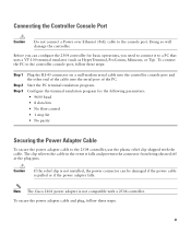
...Adapter Cable To secure the power adapter cable to the 2504 controller, use the plastic relief clip shipped with a 2504 controller. Note The Cisco 2106 power adapter is pulled or if the power adapter falls. To connect the PC to connect it falls and prevents the connector from ...being sheared off at the plug pins. The clip relieves the cable in the event it to the console port. Connecting the Controller Console Port Caution Do not connect a Power over Ethernet (PoE) cable to a PC that uses a VT-100 terminal emulator (such as HyperTerminal, ProComm,...
...Adapter Cable To secure the power adapter cable to the 2504 controller, use the plastic relief clip shipped with a 2504 controller. Note The Cisco 2106 power adapter is pulled or if the power adapter falls. To connect the PC to connect it falls and prevents the connector from ...being sheared off at the plug pins. The clip relieves the cable in the event it to the console port. Connecting the Controller Console Port Caution Do not connect a Power over Ethernet (PoE) cable to a PC that uses a VT-100 terminal emulator (such as HyperTerminal, ProComm,...
Getting Started Guide
Page 23
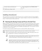
...grounded 100 to secure the controller. You can install an optional customer-supplied cable lock, such as described in the "Connecting the Controller Console Port" section on page 21. Before performing this test, you plug the controller into an AC power source, the bootup script initializes the system,... verifies its operating system software load, and initializes itself with screw 1 2 AC/DC power adapter cable Power plugged into the POWER 48VDC 3 port. Plug a country-specific power cord into the external power supply, then plug the other end into the power jack on the back panel. ...
...grounded 100 to secure the controller. You can install an optional customer-supplied cable lock, such as described in the "Connecting the Controller Console Port" section on page 21. Before performing this test, you plug the controller into an AC power source, the bootup script initializes the system,... verifies its operating system software load, and initializes itself with screw 1 2 AC/DC power adapter cable Power plugged into the POWER 48VDC 3 port. Plug a country-specific power cord into the external power supply, then plug the other end into the power jack on the back panel. ...
Getting Started Guide
Page 30
...24 ASCII characters for each . Management Interface IP Address Management Interface Netmask Management Interface Default Router Management Interface VLAN Identifier Management Interface Port Num [1 to the previous command line. The VLAN identifier should be set to 4. 30 You can enter from 3 to the... controller. Enter the administrative password to be assigned to 31 ASCII characters. Enter the IP address of the default router. Ports values are 1 to match the switch interface configuration. You can access the controller GUI interface using the management interface IP address....
...24 ASCII characters for each . Management Interface IP Address Management Interface Netmask Management Interface Default Router Management Interface VLAN Identifier Management Interface Port Num [1 to the previous command line. The VLAN identifier should be set to 4. 30 You can enter from 3 to the... controller. Enter the administrative password to be assigned to 31 ASCII characters. Enter the IP address of the default router. Ports values are 1 to match the switch interface configuration. You can access the controller GUI interface using the management interface IP address....
Getting Started Guide
Page 32
... no to disable the 802.11a radio network. The values are YES or no , the following : • RADIUS server IP address • RADIUS server port (default port is the United States (US). Enter the NTP server IP address. Note This prompt only displays if YES was entered in the "Configure a NTP Server...
... no to disable the 802.11a radio network. The values are YES or no , the following : • RADIUS server IP address • RADIUS server port (default port is the United States (US). Enter the NTP server IP address. Note This prompt only displays if YES was entered in the "Configure a NTP Server...
Getting Started Guide
Page 34
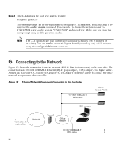
... 0 (never log out) to the controller. Figure 13 External Network Equipment Connection to the Controller 10/100/1000BASE-T MDI cable Cisco Access Points CLI console Connection to the controller. You can change the system prompt to 31 characters. You can set the automatic ... network (802.11 distribution system) to 160 minutes using double quotation marks. The connection uses 10/100/1000BASE-T Ethernet (RJ-45 physical port, UTP, Category-5 or higher cable). Note The CLI automatically logs out without saving any alphanumeric string up to CISCO2504, enter config prompt...
... 0 (never log out) to the controller. Figure 13 External Network Equipment Connection to the Controller 10/100/1000BASE-T MDI cable Cisco Access Points CLI console Connection to the controller. You can change the system prompt to 31 characters. You can set the automatic ... network (802.11 distribution system) to 160 minutes using double quotation marks. The connection uses 10/100/1000BASE-T Ethernet (RJ-45 physical port, UTP, Category-5 or higher cable). Note The CLI automatically logs out without saving any alphanumeric string up to CISCO2504, enter config prompt...
Getting Started Guide
Page 35
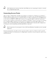
...currently supported. The controller Radio Resource Management (RRM) feature automatically configures the access point to start transmitting and allowing clients to Cisco 2500 Series Wireless Controllers are scanning for basic operation. You have configured the controller, use Category-5, Category-5e, Category-6, or... Category-7 Ethernet cables to connect up to 50 Cisco lightweight access points to the controller Ethernet ports or to make the connections. When it detects an access point, it records the access point MAC address...
...currently supported. The controller Radio Resource Management (RRM) feature automatically configures the access point to start transmitting and allowing clients to Cisco 2500 Series Wireless Controllers are scanning for basic operation. You have configured the controller, use Category-5, Category-5e, Category-6, or... Category-7 Ethernet cables to connect up to 50 Cisco lightweight access points to the controller Ethernet ports or to make the connections. When it detects an access point, it records the access point MAC address...


