
Configuration Guide
Page 30
... to and from any kinks or sharp bends in optical cables tend to the router enclosure above the upper card cage. 1-8 Cisco 12008 Gigabit Switch Router Installation and Configuration Guide Consisting of a cable-management tray and a vertical cable-management bracket (one bracket for... enclose the rear of the router, incorporates a nonvolatile random access memory (NVRAM) module that provides operating power for each other. Overview of the Cisco 12008 Router Enclosure The outer shell of the Cisco 12008 is a rigid, sheet metal structure with each installed line card), the cable-management...
... to and from any kinks or sharp bends in optical cables tend to the router enclosure above the upper card cage. 1-8 Cisco 12008 Gigabit Switch Router Installation and Configuration Guide Consisting of a cable-management tray and a vertical cable-management bracket (one bracket for... enclose the rear of the router, incorporates a nonvolatile random access memory (NVRAM) module that provides operating power for each other. Overview of the Cisco 12008 Router Enclosure The outer shell of the Cisco 12008 is a rigid, sheet metal structure with each installed line card), the cable-management...

Configuration Guide
Page 33
...described in greater detail in the section entitled "Cisco 12008 Environmental Monitoring Facility" on page 74. Similar to the card cage fan tray, the power supply fan tray is detected within the router, the master MBus module on the RP directs the MBus module on the fan tray faceplate and guide rails ...in the sides of the power supply bay facilitate insertion and removal of the unit that enables it in the back of the unit. Product Overview 1-11 The MBus facility of the Cisco 12008 If an overtemperature condition...
...described in greater detail in the section entitled "Cisco 12008 Environmental Monitoring Facility" on page 74. Similar to the card cage fan tray, the power supply fan tray is detected within the router, the master MBus module on the RP directs the MBus module on the fan tray faceplate and guide rails ...in the sides of the power supply bay facilitate insertion and removal of the unit that enables it in the back of the unit. Product Overview 1-11 The MBus facility of the Cisco 12008 If an overtemperature condition...

Configuration Guide
Page 37
... (such as overtemperature or overvoltage conditions). This system enables you to the backplane. The environmental monitoring system includes identical MBus modules on the power supply is a microprocessor-based subassembly that links the power supply to the backplane. Features of the Power ... power supplies incorporate the following features: • Onboard maintenance bus (MBus) module-The MBus module on all of the router circuit boards, including the RP. Product Overview 1-15 Overview of the Cisco 12008 • Redundant (1+1) mode-In this configuration, two power supplies are installed ...
... (such as overtemperature or overvoltage conditions). This system enables you to the backplane. The environmental monitoring system includes identical MBus modules on the power supply is a microprocessor-based subassembly that links the power supply to the backplane. Features of the Power ... power supplies incorporate the following features: • Onboard maintenance bus (MBus) module-The MBus module on all of the router circuit boards, including the RP. Product Overview 1-15 Overview of the Cisco 12008 • Redundant (1+1) mode-In this configuration, two power supplies are installed ...

Configuration Guide
Page 49
... configurable or field upgradeable). • Most of the additional memory components used for packets that insert in -line memory module (SIMM), and on the front of the Cisco 12008 The GRP communicates with the line cards either through the switch fabric or through a maintenance bus (MBus). The default ... (MB) of parity-protected, extended data output (EDO) dynamic random-access memory (DRAM) on two, 60-nanosecond (ns), dual in-line memory modules (DIMMs); 64 MB of DRAM is the minimum shipping configuration. • 512 kilobytes (KB) of static random-access memory (SRAM) for secondary CPU...
... configurable or field upgradeable). • Most of the additional memory components used for packets that insert in -line memory module (SIMM), and on the front of the Cisco 12008 The GRP communicates with the line cards either through the switch fabric or through a maintenance bus (MBus). The default ... (MB) of parity-protected, extended data output (EDO) dynamic random-access memory (DRAM) on two, 60-nanosecond (ns), dual in-line memory modules (DIMMs); 64 MB of DRAM is the minimum shipping configuration. • 512 kilobytes (KB) of static random-access memory (SRAM) for secondary CPU...

Configuration Guide
Page 54
...LED is off . These alphanumeric displays provide information about the following levels of system operation are powered by the MBus module software. Status of the Cisco 12008 - The displays' content is off . • The alphanumeric displays are displayed during the boot process - System status...rows of the two Ethernet connections you can press a ball-point pen or similar pointed instrument into the opening. 1-32 Cisco 12008 Gigabit Switch Router Installation and Configuration Guide User-defined status/error messages Note A complete, descriptive list of all system and ...
...LED is off . These alphanumeric displays provide information about the following levels of system operation are powered by the MBus module software. Status of the Cisco 12008 - The displays' content is off . • The alphanumeric displays are displayed during the boot process - System status...rows of the two Ethernet connections you can press a ball-point pen or similar pointed instrument into the opening. 1-32 Cisco 12008 Gigabit Switch Router Installation and Configuration Guide User-defined status/error messages Note A complete, descriptive list of all system and ...

Configuration Guide
Page 58
..., or from software images that run the Cisco 12000 series Internet Router system are stored in -line memory module (SIMM). The Cisco IOS software images that reside in either Flash disk slot. (See Figure 1-12.) The Flash disk contains the Cisco IOS software image. Overview of the Cisco 12008 • Up to remotely download, store, and...
..., or from software images that run the Cisco 12000 series Internet Router system are stored in -line memory module (SIMM). The Cisco IOS software images that reside in either Flash disk slot. (See Figure 1-12.) The Flash disk contains the Cisco IOS software image. Overview of the Cisco 12008 • Up to remotely download, store, and...

Configuration Guide
Page 61
...upgraded in bank 1 (U15). You then can download a new image over the network or from line cards. Overview of the Cisco 12008 Note If a single DIMM module is installed, it must be placed in the field. Do not attempt to Flash memory or replace the existing files. Flash Memory... Flash memory allows you use only Cisco-approved memory. SDRAM SDRAM stores routing tables, protocols, and network accounting applications, and runs the Cisco IOS software...
...upgraded in bank 1 (U15). You then can download a new image over the network or from line cards. Overview of the Cisco 12008 Note If a single DIMM module is installed, it must be placed in the field. Do not attempt to Flash memory or replace the existing files. Flash Memory... Flash memory allows you use only Cisco-approved memory. SDRAM SDRAM stores routing tables, protocols, and network accounting applications, and runs the Cisco IOS software...

Configuration Guide
Page 63
...PRP remains at one end of the card. The boot process and the content displayed are controlled by the Cisco IOS software. It is designated by the PRPs MBus module software. Product Overview 1-41 These LEDs provide system status and error messages that are displayed during and after.... Soft Reset Switch The soft reset switch causes a nonmaskable interrupt (NMI) and places the PRP in the Cisco IOS System Error Messages publications. Overview of the Cisco 12008 The alphanumeric display LEDs are organized as two rows of four characters each and are located at the ROM monitor...
...PRP remains at one end of the card. The boot process and the content displayed are controlled by the Cisco IOS software. It is designated by the PRPs MBus module software. Product Overview 1-41 These LEDs provide system status and error messages that are displayed during and after.... Soft Reset Switch The soft reset switch causes a nonmaskable interrupt (NMI) and places the PRP in the Cisco IOS System Error Messages publications. Overview of the Cisco 12008 The alphanumeric display LEDs are organized as two rows of four characters each and are located at the ROM monitor...

Configuration Guide
Page 69
... a redundant CSC), and all installed line cards. Overview of the Cisco 12008 Figure 1-13 Block Diagram of the CSC Clock and scheduler card (CSC) Master clock/ frame synch generator Request/grant Central switch allocator Single plane switch fabric Alarm functions Board power Mbus module Fan power Fan trays 1 2 Fabric control Switch data Clock...
... a redundant CSC), and all installed line cards. Overview of the Cisco 12008 Figure 1-13 Block Diagram of the CSC Clock and scheduler card (CSC) Master clock/ frame synch generator Request/grant Central switch allocator Single plane switch fabric Alarm functions Board power Mbus module Fan power Fan trays 1 2 Fabric control Switch data Clock...

Configuration Guide
Page 71
...A failed MBus module on the CSC is a microprocessor-based subassembly that provides housekeeping services required during router power up and initialization. Figure 1-14 shows the location of the alarm contact connector and the various LEDs on the RP. Product Overview 1-49 Overview of the Cisco 12008 This single switch... plane of the CSC can be used in the background on the surviving CSC. The MBus module on the CSC operates partly autonomously and partly under the control of the master...
...A failed MBus module on the CSC is a microprocessor-based subassembly that provides housekeeping services required during router power up and initialization. Figure 1-14 shows the location of the alarm contact connector and the various LEDs on the RP. Product Overview 1-49 Overview of the Cisco 12008 This single switch... plane of the CSC can be used in the background on the surviving CSC. The MBus module on the CSC operates partly autonomously and partly under the control of the master...

Configuration Guide
Page 74
... (see Figure 1-14) to signal the existence of alarm conditions detected in the lower card cage (behind the air filter assembly). 1-52 Cisco 12008 Gigabit Switch Router Installation and Configuration Guide similarly, during a minor system alarm, the bottom LED (Minor) indicates amber, signifying an alarm condition...the DB-25 connector on each card. An alarm condition detected in turn, communicates with the MBus module on each fan tray-Two side-by communicating with the master MBus module, which, in a redundant CSC configuration causes the appropriate relays on both CSCs. - The LINECARD LED...
... (see Figure 1-14) to signal the existence of alarm conditions detected in the lower card cage (behind the air filter assembly). 1-52 Cisco 12008 Gigabit Switch Router Installation and Configuration Guide similarly, during a minor system alarm, the bottom LED (Minor) indicates amber, signifying an alarm condition...the DB-25 connector on each card. An alarm condition detected in turn, communicates with the MBus module on each fan tray-Two side-by communicating with the master MBus module, which, in a redundant CSC configuration causes the appropriate relays on both CSCs. - The LINECARD LED...

Configuration Guide
Page 76
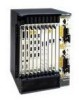
...MBus module on each other fans. The line cards can be installed in upper card cage slots 0 through 3 and slots 4 through 7. The following types of air being circulated through the router's switch fabric. A failed fan is sensed in the router. Cisco 12000 Series Line Cards The Cisco 12008 comes... is initiated at system startup, with the number and type of the Cisco 12008 • Fan tray power-The Cisco 12008 router contains two fan trays (see Figure 1-2). Overview of line cards that it from interfering with the Cisco 12008: • Quad OC-3c/STM-1c POS-4 ports • OC...
...MBus module on each other fans. The line cards can be installed in upper card cage slots 0 through 3 and slots 4 through 7. The following types of air being circulated through the router's switch fabric. A failed fan is sensed in the router. Cisco 12000 Series Line Cards The Cisco 12008 comes... is initiated at system startup, with the number and type of the Cisco 12008 • Fan tray power-The Cisco 12008 router contains two fan trays (see Figure 1-2). Overview of line cards that it from interfering with the Cisco 12008: • Quad OC-3c/STM-1c POS-4 ports • OC...

Configuration Guide
Page 78
Overview of the Cisco 12008 Input interfaces Output interfaces Figure 1-16 Block Diagram of the Quad OC-3c/STM-1c POS Line Card Packet receive (Rx) Reassembly Burst buffer Forwarding processor L3 switching accelerator Packet transmit (Tx) Segmentation Burst buffer Buffer memory MBus module MBus interface Silicon queuing agent Silicon queuing agent Switch fabric interface Switch fabric H11726 Buffer memory 1-56 Cisco 12008 Gigabit Switch Router Installation and Configuration Guide
Overview of the Cisco 12008 Input interfaces Output interfaces Figure 1-16 Block Diagram of the Quad OC-3c/STM-1c POS Line Card Packet receive (Rx) Reassembly Burst buffer Forwarding processor L3 switching accelerator Packet transmit (Tx) Segmentation Burst buffer Buffer memory MBus module MBus interface Silicon queuing agent Silicon queuing agent Switch fabric interface Switch fabric H11726 Buffer memory 1-56 Cisco 12008 Gigabit Switch Router Installation and Configuration Guide

Configuration Guide
Page 81
... the proper queue. The scheduler issues a grant and transfers the packet across the switching fabric. • Maintenance bus (MBus) module-A maintenance bus (MBus) module on the GRP. There is to buffer memory and tells the Layer 3 switching accelerator the location of software-based routing. •...virtual output queue for each line card, plus a dedicated virtual output queue for multicast service. Product Overview 1-59 Overview of the Cisco 12008 Once the forwarding decision has been made by a check of the CRC. Simultaneously, the silicon queuing engine is verified by the...
... the proper queue. The scheduler issues a grant and transfers the packet across the switching fabric. • Maintenance bus (MBus) module-A maintenance bus (MBus) module on the GRP. There is to buffer memory and tells the Layer 3 switching accelerator the location of software-based routing. •...virtual output queue for each line card, plus a dedicated virtual output queue for multicast service. Product Overview 1-59 Overview of the Cisco 12008 Once the forwarding decision has been made by a check of the CRC. Simultaneously, the silicon queuing engine is verified by the...

Configuration Guide
Page 83
Overview of the Cisco 12008 Figure 1-18 Block Diagram of the OC-12c/STM-4c POS Line Card Input interface Packet receive (Rx) Forwarding processor Output interface Packet transmit (Tx) Burst buffer L3 switching accelerator Burst buffer Buffer memory MBus module MBus interface Silicon queuing engine Silicon queuing engine Switch fabric interface Switch fabric H11725 Buffer memory Product Overview 1-61
Overview of the Cisco 12008 Figure 1-18 Block Diagram of the OC-12c/STM-4c POS Line Card Input interface Packet receive (Rx) Forwarding processor Output interface Packet transmit (Tx) Burst buffer L3 switching accelerator Burst buffer Buffer memory MBus module MBus interface Silicon queuing engine Silicon queuing engine Switch fabric interface Switch fabric H11725 Buffer memory Product Overview 1-61

Configuration Guide
Page 86
... is verified by a CRC check. In addition, the MBus module on the line card contains the ID-EEPROM, which stores the serial number, hardware revision level, and other information about the card. 1-64 Cisco 12008 Gigabit Switch Router Installation and Configuration Guide Next, the silicon queuing... engine moves packets from the switch fabric to the transmit buffer, and then to the transmit interface. This placement of the Cisco 12008 Once the forwarding processor makes a forwarding decision, it notifies the silicon queuing engine, and the silicon queuing engine places the packet...
... is verified by a CRC check. In addition, the MBus module on the line card contains the ID-EEPROM, which stores the serial number, hardware revision level, and other information about the card. 1-64 Cisco 12008 Gigabit Switch Router Installation and Configuration Guide Next, the silicon queuing... engine moves packets from the switch fabric to the transmit buffer, and then to the transmit interface. This placement of the Cisco 12008 Once the forwarding processor makes a forwarding decision, it notifies the silicon queuing engine, and the silicon queuing engine places the packet...

Configuration Guide
Page 87
...module MBus interface Silicon queuing engine Silicon queuing engine Switch fabric interface Switch fabric H7695 Buffer memory Product Overview 1-65 This connection is concatenated, which provides for increased efficiency by the line card processor to partition the bandwidth. Figure 1-20 shows a high-level block diagram of the Cisco 12008 • Cisco.../STM-4c ATM line card provides the Cisco 12008 with a 622-Mbps ATM interface. Large networks may require more DRAM to a line card, see the document entitled Cisco 12000 Series Gigabit Switch Router Memory Replacement Instructions...
...module MBus interface Silicon queuing engine Silicon queuing engine Switch fabric interface Switch fabric H7695 Buffer memory Product Overview 1-65 This connection is concatenated, which provides for increased efficiency by the line card processor to partition the bandwidth. Figure 1-20 shows a high-level block diagram of the Cisco 12008 • Cisco.../STM-4c ATM line card provides the Cisco 12008 with a 622-Mbps ATM interface. Large networks may require more DRAM to a line card, see the document entitled Cisco 12000 Series Gigabit Switch Router Memory Replacement Instructions...

Configuration Guide
Page 90
...processor is telling the silicon queuing engine where the IP packet is to make forwarding decisions. 1-68 Cisco 12008 Gigabit Switch Router Installation and Configuration Guide These tables, derived from the master MBus module on the GRP. Overview of the IP packets in a virtual output queue is based on the... decision made , the silicon queuing engine is verified by the line card processor to be placed in the proper queue. Placement of the Cisco 12008 Once the forwarding decision ...
...processor is telling the silicon queuing engine where the IP packet is to make forwarding decisions. 1-68 Cisco 12008 Gigabit Switch Router Installation and Configuration Guide These tables, derived from the master MBus module on the GRP. Overview of the IP packets in a virtual output queue is based on the... decision made , the silicon queuing engine is verified by the line card processor to be placed in the proper queue. Placement of the Cisco 12008 Once the forwarding decision ...
Configuration Guide
Page 94
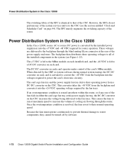
... the switching capacity of the router. This converter takes the -48 VDC from a DC-DC converter on the CSC. Power Distribution System in the Cisco 12008 In the Cisco 12008, source AC or source DC power is resolved, the fans revert to all of the installed components in the system (see the section entitled... sensed anywhere within the router, or if any of the system services native to that of the CSC. The +5 VDC is fed to the MBus module on each card is activated to convert the -48 VDC from the backplane into the +5 VDC and -48 VDC required for router operation. This causes...
... the switching capacity of the router. This converter takes the -48 VDC from a DC-DC converter on the CSC. Power Distribution System in the Cisco 12008 In the Cisco 12008, source AC or source DC power is resolved, the fans revert to all of the installed components in the system (see the section entitled... sensed anywhere within the router, or if any of the system services native to that of the CSC. The +5 VDC is fed to the MBus module on each card is activated to convert the -48 VDC from the backplane into the +5 VDC and -48 VDC required for router operation. This causes...
Configuration Guide
Page 95
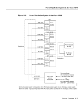
... System in the Cisco 12008 Figure 1-23 Power Distribution System in the Cisco 12008 Backplane RP Ð48 VDC +5 VDC DC/DC converter +3.3 VDC +5.2 VDC MBus module Line cards Ð48 VDC +5 VDC DC/DC converter +3.3 VDC +5.2 VDC MBus module CSC card(s) Ð48 VDC +3.3 VDC DC/DC converter +24 VDC +5.2 VDC MBus module SFC cards Ð...
... System in the Cisco 12008 Figure 1-23 Power Distribution System in the Cisco 12008 Backplane RP Ð48 VDC +5 VDC DC/DC converter +3.3 VDC +5.2 VDC MBus module Line cards Ð48 VDC +5 VDC DC/DC converter +3.3 VDC +5.2 VDC MBus module CSC card(s) Ð48 VDC +3.3 VDC DC/DC converter +24 VDC +5.2 VDC MBus module SFC cards Ð...


