
Configuration Guide
Page 6
...Performance Route Processor 1-34 Switch Fabric of the Cisco 12008 1-43 Clock and Scheduler Card 1-44 Cisco 12000 Series Line Cards 1-54 Air Filter Assembly 1-69 Lower Card Cage and Associated Components 1-69 Switch Fabric Cards 1-70 Power Distribution System in the Cisco 12008 1-72 Cisco 12008 Environmental Monitoring Facility 1-74 System Specifications 1-75 Agency...Guidelines 2-19 EMI Considerations 2-20 Synchronous Optical Network Connection Guidelines 2-21 Power Budget 2-22 Approximating the Line Card Power Margin 2-23 vi Cisco 12008 Gigabit Switch Router Installation and Configuration Guide
...Performance Route Processor 1-34 Switch Fabric of the Cisco 12008 1-43 Clock and Scheduler Card 1-44 Cisco 12000 Series Line Cards 1-54 Air Filter Assembly 1-69 Lower Card Cage and Associated Components 1-69 Switch Fabric Cards 1-70 Power Distribution System in the Cisco 12008 1-72 Cisco 12008 Environmental Monitoring Facility 1-74 System Specifications 1-75 Agency...Guidelines 2-19 EMI Considerations 2-20 Synchronous Optical Network Connection Guidelines 2-21 Power Budget 2-22 Approximating the Line Card Power Margin 2-23 vi Cisco 12008 Gigabit Switch Router Installation and Configuration Guide
Configuration Guide
Page 10
... the diag Command 6-2 Diagnostic Testing Sequence 6-3 Loading and Running Diagnostics 6-4 Diagnostic Examples 6-5 Without verbose Option 6-6 With verbose Option 6-7 Failed Diagnostic 6-9 Maintaining the Cisco 12008 7-1 Cleaning the Air Filter 7-2 Installing and Removing a Blank Filler Panel 7-5 Adding, Removing, or Replacing an AC-Input Power Supply 7-7 Adding an AC-Input Power Supply 7-7 Removing an... Installation of a Fan Tray 7-48 Status LEDs for the Fan Trays 7-48 Removing and Replacing the RP 7-51 Removing the RP 7-52 x Cisco 12008 Gigabit Switch Router Installation and Configuration Guide
... the diag Command 6-2 Diagnostic Testing Sequence 6-3 Loading and Running Diagnostics 6-4 Diagnostic Examples 6-5 Without verbose Option 6-6 With verbose Option 6-7 Failed Diagnostic 6-9 Maintaining the Cisco 12008 7-1 Cleaning the Air Filter 7-2 Installing and Removing a Blank Filler Panel 7-5 Adding, Removing, or Replacing an AC-Input Power Supply 7-7 Adding an AC-Input Power Supply 7-7 Removing an... Installation of a Fan Tray 7-48 Status LEDs for the Fan Trays 7-48 Removing and Replacing the RP 7-51 Removing the RP 7-52 x Cisco 12008 Gigabit Switch Router Installation and Configuration Guide
Configuration Guide
Page 23
... Tray • AC-Input and DC-Input Power Supplies • Upper Card Cage and Associated Components • Air Filter Assembly • Lower Card Cage and Associated Components • Power Distribution System in the Cisco 12008 • Cisco 12008 Environmental Monitoring Facility • System Specifications • Agency Approvals Product Overview 1-1 The following sections are included in...
... Tray • AC-Input and DC-Input Power Supplies • Upper Card Cage and Associated Components • Air Filter Assembly • Lower Card Cage and Associated Components • Power Distribution System in the Cisco 12008 • Cisco 12008 Environmental Monitoring Facility • System Specifications • Agency Approvals Product Overview 1-1 The following sections are included in...

Configuration Guide
Page 29
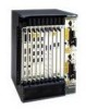
or DC-input power supplies (AC-input power supplies shown) Power supply fan tray Product Overview 1-7 Overview of the Cisco 12008 Figure 1-2 Major Components of the Cisco 12008 Router enclosure Cable-management tray H7691 EJECT SSLLOOTT--01 RESET AUX Alarm Alarm ACO/LT ACO/LT CONSOLE CriticaMl ajor Minor Alarms CriticaMl ... Enabled CSC RJ-45 MII PLWINRECSAPRLYD Fan Fail PLWINRECSAPRLYD Fan Fail Fail Enabled SFC Fail Enabled SFC GIGABIT ROUTE PROCESSOR CSC-8 CSC-8 Air filter assembly (lower card cage behind air filter assembly contains card cage fan tray and SFCs) AC-
or DC-input power supplies (AC-input power supplies shown) Power supply fan tray Product Overview 1-7 Overview of the Cisco 12008 Figure 1-2 Major Components of the Cisco 12008 Router enclosure Cable-management tray H7691 EJECT SSLLOOTT--01 RESET AUX Alarm Alarm ACO/LT ACO/LT CONSOLE CriticaMl ajor Minor Alarms CriticaMl ... Enabled CSC RJ-45 MII PLWINRECSAPRLYD Fan Fail PLWINRECSAPRLYD Fan Fail Fail Enabled SFC Fail Enabled SFC GIGABIT ROUTE PROCESSOR CSC-8 CSC-8 Air filter assembly (lower card cage behind air filter assembly contains card cage fan tray and SFCs) AC-

Configuration Guide
Page 32
... mounted on each side of the metal carrier. Under normal operating conditions, the variable-speed fans in the lower card cage behind the air filter assembly (see Figure 1-2). Thus, the vertical cable-management bracket enables you to neatly "dress" all the interface cables in the bottom of... and seat the cable in place as you connect them to • Conserve power • Reduce noise • Minimize fan wear 1-10 Cisco 12008 Gigabit Switch Router Installation and Configuration Guide Later, when you remove or replace a line card, you need only disconnect the cables from the individual...
... mounted on each side of the metal carrier. Under normal operating conditions, the variable-speed fans in the lower card cage behind the air filter assembly (see Figure 1-2). Thus, the vertical cable-management bracket enables you to neatly "dress" all the interface cables in the bottom of... and seat the cable in place as you connect them to • Conserve power • Reduce noise • Minimize fan wear 1-10 Cisco 12008 Gigabit Switch Router Installation and Configuration Guide Later, when you remove or replace a line card, you need only disconnect the cables from the individual...

Configuration Guide
Page 73
... facility, a visible indication can be provided, and/or an audible alarm can be sent to the router, thus supporting a telco style of the Cisco 12008 - Only safety extra-low voltage (SELV) external alarm circuits can test the operability of an alarm in the router. A visual alarm, however, ... (see the following section entitled "System Alarm LEDS"). The alarm signals sent to this DB-25 connector are visible only when the air filter assembly is attached to silence the alarm. Overview of handling alarm conditions in associated equipment. - Alarm cutoff reset/lamp test (ACO/LT)...
... facility, a visible indication can be provided, and/or an audible alarm can be sent to the router, thus supporting a telco style of the Cisco 12008 - Only safety extra-low voltage (SELV) external alarm circuits can test the operability of an alarm in the router. A visual alarm, however, ... (see the following section entitled "System Alarm LEDS"). The alarm signals sent to this DB-25 connector are visible only when the air filter assembly is attached to silence the alarm. Overview of handling alarm conditions in associated equipment. - Alarm cutoff reset/lamp test (ACO/LT)...

Configuration Guide
Page 74
... LEDs on the CSC faceplate indicates red; finally, during a major alarm, the middle LED (Major) on each circuit board. - Overview of the Cisco 12008 In a system equipped with two CSCs, pressing the ACO/LT button on one CSC is closed, sending a corresponding signal to the DB-25 alarm... status of the CSC. - When the fault condition is resolved, MBus software running in the lower card cage (behind the air filter assembly). 1-52 Cisco 12008 Gigabit Switch Router Installation and Configuration Guide FAN FAIL Status LEDs for each card. The LINECARD LED on the left pertains to the card...
... LEDs on the CSC faceplate indicates red; finally, during a major alarm, the middle LED (Major) on each circuit board. - Overview of the Cisco 12008 In a system equipped with two CSCs, pressing the ACO/LT button on one CSC is closed, sending a corresponding signal to the DB-25 alarm... status of the CSC. - When the fault condition is resolved, MBus software running in the lower card cage (behind the air filter assembly). 1-52 Cisco 12008 Gigabit Switch Router Installation and Configuration Guide FAN FAIL Status LEDs for each card. The LINECARD LED on the left pertains to the card...

Configuration Guide
Page 75
... -48 VDC being delivered to shut down , at which of the SFCs has failed, you must remove the air filter assembly and examine the status of the LEDs on each SFC. Product Overview 1-53 Overview of the Cisco 12008 If the FAIL LED goes on, it into the CSC for the fan trays.
... -48 VDC being delivered to shut down , at which of the SFCs has failed, you must remove the air filter assembly and examine the status of the LEDs on each SFC. Product Overview 1-53 Overview of the Cisco 12008 If the FAIL LED goes on, it into the CSC for the fan trays.

Configuration Guide
Page 91
... into the router's environment. Procedures for vacuuming and replacing the air filter are provided to a line card, see Figure 1-22). Product Overview 1-69 Although the Cisco 12008 will run without an air filter, the air filter should always be present and maintained properly, especially in the upper card...Cage and Associated Components The lower card cage, located directly behind the air filter assembly (see Figure 1-22), houses the card cage fan tray and an optional set of the Cisco 12008 Large networks may require more often in Chapter 7. For information on adding memory...
... into the router's environment. Procedures for vacuuming and replacing the air filter are provided to a line card, see Figure 1-22). Product Overview 1-69 Although the Cisco 12008 will run without an air filter, the air filter should always be present and maintained properly, especially in the upper card...Cage and Associated Components The lower card cage, located directly behind the air filter assembly (see Figure 1-22), houses the card cage fan tray and an optional set of the Cisco 12008 Large networks may require more often in Chapter 7. For information on adding memory...

Configuration Guide
Page 93
Product Overview 1-71 Overview of the Cisco 12008 Figure 1-22 Components in the Lower Card Cage H7693 Air filter assembly SFC1 SFC2 Alarm Alarm ACO/LT ACO/LT CriticaMl ajor Minor Alarms CriticaMl ajor Minor Alarms Fail Enabled CSC Fail Enabled CSC PLWINRECSAPRLYD Fan Fail PLWINRECSAPRLYD Fan Fail Fail Enabled SFC CSC-8 Fail Enabled SFC CSC-8 1 SFC0 EJECT SSLLOOTT--01 RESET AUX CONSOLE COLL RX LINK TX RJ-45 MII GIGABIT ROUTE PROCESSOR 2 ESD socket Card cage fan tray Lower card cage Switch fabric cards (SFCs)
Product Overview 1-71 Overview of the Cisco 12008 Figure 1-22 Components in the Lower Card Cage H7693 Air filter assembly SFC1 SFC2 Alarm Alarm ACO/LT ACO/LT CriticaMl ajor Minor Alarms CriticaMl ajor Minor Alarms Fail Enabled CSC Fail Enabled CSC PLWINRECSAPRLYD Fan Fail PLWINRECSAPRLYD Fan Fail Fail Enabled SFC CSC-8 Fail Enabled SFC CSC-8 1 SFC0 EJECT SSLLOOTT--01 RESET AUX CONSOLE COLL RX LINK TX RJ-45 MII GIGABIT ROUTE PROCESSOR 2 ESD socket Card cage fan tray Lower card cage Switch fabric cards (SFCs)

Configuration Guide
Page 109
... of the equipment rack as low as possible without sacrificing router utility, accessibility, or serviceability. The rack-mounting hardware included with the Cisco 12008 is drawn into the router's air filter assembly, adding to size and weight considerations. If the enclosed rack in which you install the router does not have a ventilation fan...
... of the equipment rack as low as possible without sacrificing router utility, accessibility, or serviceability. The rack-mounting hardware included with the Cisco 12008 is drawn into the router's air filter assembly, adding to size and weight considerations. If the enclosed rack in which you install the router does not have a ventilation fan...
Configuration Guide
Page 112
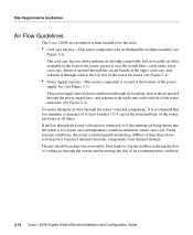
...system power to clog the air filter, reducing the flow of cooling air through the system and increasing the risk of the router enclosure at all times. If airflow through the circuit boards in the front and back of an overtemperature condition. 2-10 Cisco 12008 Gigabit Switch Router Installation and Configuration... drawn into the router is too warm, an overtemperature condition within the router can occur. Site Requirements Guidelines Air Flow Guidelines The Cisco 12008 air circulation system includes two fan trays: • Card cage fan tray-This router component is located behind the air...
...system power to clog the air filter, reducing the flow of cooling air through the system and increasing the risk of the router enclosure at all times. If airflow through the circuit boards in the front and back of an overtemperature condition. 2-10 Cisco 12008 Gigabit Switch Router Installation and Configuration... drawn into the router is too warm, an overtemperature condition within the router can occur. Site Requirements Guidelines Air Flow Guidelines The Cisco 12008 air circulation system includes two fan trays: • Card cage fan tray-This router component is located behind the air...

Configuration Guide
Page 113
Preparing for Installation 2-11 Site Requirements Guidelines H11403 Captive installation screw Insertion/extraction tab Air filter assembly Alarm Alarm ACO/LT ACO/LT CriticaMl ajor Minor Alarms CriticaMl ajor Minor Alarms Fail Enabled CSC Fail Enabled CSC SPLY PLWINRECARD Fan Fail PLWINRECSAPRLYD Fan Fail Fail Enabled SFC CSC-8 Fail Enabled SFC CSC-8 Card Cage Fan Tray EJECT SSLLOOTT--01 RESET AUX CONSOLE COLL RX LINK TX RJ-45 MII GIGABIT ROUTE PROCESSOR Captive installation screw 1 2 Figure 2-2
Preparing for Installation 2-11 Site Requirements Guidelines H11403 Captive installation screw Insertion/extraction tab Air filter assembly Alarm Alarm ACO/LT ACO/LT CriticaMl ajor Minor Alarms CriticaMl ajor Minor Alarms Fail Enabled CSC Fail Enabled CSC SPLY PLWINRECARD Fan Fail PLWINRECSAPRLYD Fan Fail Fail Enabled SFC CSC-8 Fail Enabled SFC CSC-8 Card Cage Fan Tray EJECT SSLLOOTT--01 RESET AUX CONSOLE COLL RX LINK TX RJ-45 MII GIGABIT ROUTE PROCESSOR Captive installation screw 1 2 Figure 2-2
Configuration Guide
Page 115
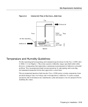
...filter assembly Ambient air Card cage fans Power supply fans Bottom Upper Rear card cage Lower card cage H7683 Temperature and Humidity Guidelines For the operating and nonoperating environmental specifications for Installation 2-13 The environmental monitors built into the Cisco 12008... protect system components from potential damage from overvoltage and overtemperature conditions. Preparing for the Cisco 12008, refer to Table 1-11 in this table; The router operates ...
...filter assembly Ambient air Card cage fans Power supply fans Bottom Upper Rear card cage Lower card cage H7683 Temperature and Humidity Guidelines For the operating and nonoperating environmental specifications for Installation 2-13 The environmental monitors built into the Cisco 12008... protect system components from potential damage from overvoltage and overtemperature conditions. Preparing for the Cisco 12008, refer to Table 1-11 in this table; The router operates ...

Configuration Guide
Page 184
... router to determine if air is being exhausted from the vents in Chapter 4, "Observing System Startup and Performing a Basic Configuration." 3-52 Cisco 12008 Gigabit Switch Router Installation and Configuration Guide You should go on. Alternatively, you can now proceed with the basic router configuration tasks, as ... up to determine if air is being drawn into the interior of the air filter assembly and the power supply fan tray to normal rotational speed in front of the router. Starting the Cisco 12008 • For the DC-input power supply(ies), the green INPUT OK LED...
... router to determine if air is being exhausted from the vents in Chapter 4, "Observing System Startup and Performing a Basic Configuration." 3-52 Cisco 12008 Gigabit Switch Router Installation and Configuration Guide You should go on. Alternatively, you can now proceed with the basic router configuration tasks, as ... up to determine if air is being drawn into the interior of the air filter assembly and the power supply fan tray to normal rotational speed in front of the router. Starting the Cisco 12008 • For the DC-input power supply(ies), the green INPUT OK LED...

Configuration Guide
Page 267
.... finally, two LEDs at the bottom of the CSC faceplate indicate the status of the SFCs installed in the lower card cage behind the air filter assembly. Such a system can be attached to reset (silence) an audible alarm. Two LEDs indicate the status of a critical, major, or minor ...for an indication of the CSC itself; Check the CSC for the attachment of a site-wide external monitoring system. Troubleshooting the Cooling Subsystem The Cisco 12008 incorporates two fan trays (see Figure 3-16). If any one of the three system alarm LEDs is mounted in the lower card cage. ...
.... finally, two LEDs at the bottom of the CSC faceplate indicate the status of the SFCs installed in the lower card cage behind the air filter assembly. Such a system can be attached to reset (silence) an audible alarm. Two LEDs indicate the status of a critical, major, or minor ...for an indication of the CSC itself; Check the CSC for the attachment of a site-wide external monitoring system. Troubleshooting the Cooling Subsystem The Cisco 12008 incorporates two fan trays (see Figure 3-16). If any one of the three system alarm LEDs is mounted in the lower card cage. ...

Configuration Guide
Page 268
... components and electronic circuitry. they provide sufficient cooling air for the hum of the slot. 4 Firmly reseat the fan tray in the slot. 5-18 Cisco 12008 Gigabit Switch Router Installation and Configuration Guide In a noisy environment, you might have to the chassis frame. 3 Grasp the fan tray carrier by its ... tray provides connectivity to it through the backplane from a DC-DC converter on the CSC faceplate is confirmed as follows: 1 Remove the air filter assembly from the DC-DC converter on the CSC is on (amber), reseat the card cage fan tray in the back of the power supply...
... components and electronic circuitry. they provide sufficient cooling air for the hum of the slot. 4 Firmly reseat the fan tray in the slot. 5-18 Cisco 12008 Gigabit Switch Router Installation and Configuration Guide In a noisy environment, you might have to the chassis frame. 3 Grasp the fan tray carrier by its ... tray provides connectivity to it through the backplane from a DC-DC converter on the CSC faceplate is confirmed as follows: 1 Remove the air filter assembly from the DC-DC converter on the CSC is on (amber), reseat the card cage fan tray in the back of the power supply...

Configuration Guide
Page 269
... in the upper and lower card cages and the power supplies. Troubleshooting the Cooling Subsystem 5 Tighten the fan tray captive installation screws. 6 Reinstall the air filter assembly. Fan speed is faulty and should be replaced. - Either command displays information about the internal system environment, including voltage measurements on the CSC increases...
... in the upper and lower card cages and the power supplies. Troubleshooting the Cooling Subsystem 5 Tighten the fan tray captive installation screws. 6 Reinstall the air filter assembly. Fan speed is faulty and should be replaced. - Either command displays information about the internal system environment, including voltage measurements on the CSC increases...

Configuration Guide
Page 270
...; Troubleshooting Internetworking Systems • Debug Command Reference • System Error Messages 5-20 Cisco 12008 Gigabit Switch Router Installation and Configuration Guide There are available for troubleshooting your Cisco 12008 installation: • The various configuration notes for assistance. Additional Troubleshooting Reference Information The...(one for inlet air temperature and one for the fan trays. If a fan tray is not entering the air filter assembly; Although an overtemperature condition is unlikely at least 12 inches (30.5 cm) - in the immediate environment is ...
...; Troubleshooting Internetworking Systems • Debug Command Reference • System Error Messages 5-20 Cisco 12008 Gigabit Switch Router Installation and Configuration Guide There are available for troubleshooting your Cisco 12008 installation: • The various configuration notes for assistance. Additional Troubleshooting Reference Information The...(one for inlet air temperature and one for the fan trays. If a fan tray is not entering the air filter assembly; Although an overtemperature condition is unlikely at least 12 inches (30.5 cm) - in the immediate environment is ...

Configuration Guide
Page 281
... entitled "Safety Recommendations" in Chapter 2 to prevent problems, damage to equipment, or injury to operate properly and reliably. Maintaining the Cisco 12008 7-1 This chapter includes the following sections: • Cleaning the Air Filter • Installing and Removing a Blank Filler Panel • Adding, Removing, or Replacing an AC-Input Power Supply • Adding, Removing...
... entitled "Safety Recommendations" in Chapter 2 to prevent problems, damage to equipment, or injury to operate properly and reliably. Maintaining the Cisco 12008 7-1 This chapter includes the following sections: • Cleaning the Air Filter • Installing and Removing a Blank Filler Panel • Adding, Removing, or Replacing an AC-Input Power Supply • Adding, Removing...
