Owners Manual
Page 2
... DIAGRAM 4 4. Power circuit ...14 5-3. Printing and Display test 19 7. Displaying the Key Code 17 6-3. TROUBLESHOOTING 21 8. CIRCUIT EXPLANATION 10 5-1. IC DATA ...22 9. Printer drive circuit 15 5-5. Content of the Test ...17 6-2. Reset circuit ...14 5-4. PARTS LIST 28 SPECIFICATIONS 1 2. Display circuit...
... DIAGRAM 4 4. Power circuit ...14 5-3. Printing and Display test 19 7. Displaying the Key Code 17 6-3. TROUBLESHOOTING 21 8. CIRCUIT EXPLANATION 10 5-1. IC DATA ...22 9. Printer drive circuit 15 5-5. Content of the Test ...17 6-2. Reset circuit ...14 5-4. PARTS LIST 28 SPECIFICATIONS 1 2. Display circuit...
Owners Manual
Page 13
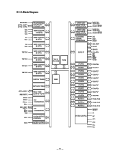
...-P06 P10-P17 P20-P27 P30-P37 P40-P47 P50-P57 P60-P67 P70-P72 P80-P87 P90-P95 P100-P103 P120-P127 P130,P131 RESET X1 X2 XT1 XT2 VDD VSS - 11 -
...-P06 P10-P17 P20-P27 P30-P37 P40-P47 P50-P57 P60-P67 P70-P72 P80-P87 P90-P95 P100-P103 P120-P127 P130,P131 RESET X1 X2 XT1 XT2 VDD VSS - 11 -
Owners Manual
Page 14
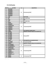
I Reset IO 7 bit input/output PORT - GND - I Sub system Clock I Main system Clock - Power Supply - A/D CONVERTER POWER SUPPLY - Application of Standard Voltage for D/A CONVERTER IO 3 bit ... 2 P121/RTP1 3 P122/RTP2 4 P123/RTP3 5 P124/RTP4 6 P125/RTP5 7 P126/RTP6 8 P127/RTP7 9 VDD 10 X2 11 X1 12 VSS 13 XT2 14 XT1 15 RESET 16 P00/INTP0 17 P01/INTP1 18 P02/INTP2/NMI 19 P03/INTP3 20 P04/INTP4 21 P05/INTP5 22 P06/INTP6 23 AVDD 24...
I Reset IO 7 bit input/output PORT - GND - I Sub system Clock I Main system Clock - Power Supply - A/D CONVERTER POWER SUPPLY - Application of Standard Voltage for D/A CONVERTER IO 3 bit ... 2 P121/RTP1 3 P122/RTP2 4 P123/RTP3 5 P124/RTP4 6 P125/RTP5 7 P126/RTP6 8 P127/RTP7 9 VDD 10 X2 11 X1 12 VSS 13 XT2 14 XT1 15 RESET 16 P00/INTP0 17 P01/INTP1 18 P02/INTP2/NMI 19 P03/INTP3 20 P04/INTP4 21 P05/INTP5 22 P06/INTP6 23 AVDD 24...
Owners Manual
Page 17
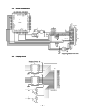
...RTP4 7 P125/RTP5 P126/RTP6 8 P127/RTP7 9 10 VDD 11 X2 X1 12 VSS 13 14 XT2 15 XT1 16 RESET P00/INTP0 17 18 P01/INTP1 19 P02/INTP2/NMI 20 P03/INTP3 P04/INTP4 21 22 P05/INTP5 ...25 LATCH 24 CLOCK 23 Vdd 22 DST4 21 GND 20 GND 19 DST3 18 Vdd 17 THERMISTOR 16 GND 15 GND 14 DST1 13 DST2 12 VP 11 VP 10 nA 8 A 4 B 6 nB 100p C15 100p ... + Stepping Motor Driver IC C28 16V10uF Display Driver IC IC2 1 I1 2 3 I2 4 I3 5 I4 I5 6 7 I6 I7 16 O1 15 O2 14 O3 13 O4 12 O5 11 O6 10 O7 VLED 8 GND 9 COM ULN2003AFW IC1 VLED 1 I1 2 3 I2 4 I3 I4...
...RTP4 7 P125/RTP5 P126/RTP6 8 P127/RTP7 9 10 VDD 11 X2 X1 12 VSS 13 14 XT2 15 XT1 16 RESET P00/INTP0 17 18 P01/INTP1 19 P02/INTP2/NMI 20 P03/INTP3 P04/INTP4 21 22 P05/INTP5 ...25 LATCH 24 CLOCK 23 Vdd 22 DST4 21 GND 20 GND 19 DST3 18 Vdd 17 THERMISTOR 16 GND 15 GND 14 DST1 13 DST2 12 VP 11 VP 10 nA 8 A 4 B 6 nB 100p C15 100p ... + Stepping Motor Driver IC C28 16V10uF Display Driver IC IC2 1 I1 2 3 I2 4 I3 5 I4 I5 6 7 I6 I7 16 O1 15 O2 14 O3 13 O4 12 O5 11 O6 10 O7 VLED 8 GND 9 COM ULN2003AFW IC1 VLED 1 I1 2 3 I2 4 I3 I4...
Owners Manual
Page 18
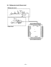
... 3 P121/RTP1 P122/RTP2 4 P123/RTP3 5 6 P124/RTP4 7 P125/RTP5 P126/RTP6 8 P127/RTP7 9 10 VDD 11 X2 12 X1 VSS 13 14 XT2 15 XT1 16 RESET P00/INTP0 17 18 P01/INTP1 19 P02/INTP2/NMI 20 P03/INTP3 P04/INTP4 21 22 P05/INTP5 23 P06/INTP6 24 AVDD...
... 3 P121/RTP1 P122/RTP2 4 P123/RTP3 5 6 P124/RTP4 7 P125/RTP5 P126/RTP6 8 P127/RTP7 9 10 VDD 11 X2 12 X1 VSS 13 14 XT2 15 XT1 16 RESET P00/INTP0 17 18 P01/INTP1 19 P02/INTP2/NMI 20 P03/INTP3 P04/INTP4 21 22 P05/INTP5 23 P06/INTP6 24 AVDD...
Owners Manual
Page 33
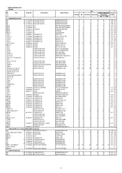
...PCB ASSY/E270-1 N 1 10140512 PCB ASSY/E270-1 N 1 10140513 PCB ASSY/E270-1 N IC4 10137724 LSI N IC4 10136098 LSI N IC6 10136173 IC/RESET N IC8 10136174 IC N IC1,2 10132897 IC Q7 10082597 TRANSISTOR Q3,11 79113038 TRANSISTOR Q18 22501601 TRANSISTOR Q17 10079246 TRANSISTOR Q1,2 10076311 TRANSISTOR D1-3,5,6,9 23902058 DIODE...DIODE D4 10905733 DIODE C3 CAPACITOR/CHIP C28 CAPACITOR/CHIP C39 CAPACITOR/CHIP C22,29 CAPACITOR/CHIP C27,30 CAPACITOR/CHIP C2,15-17,19,20,24,26, CAPACITOR/CHIP 31 C12,14,37,38 CAPACITOR/CHIP C18 CAPACITOR/CHIP RM1-4 RESISTOR/CHIP ...
...PCB ASSY/E270-1 N 1 10140512 PCB ASSY/E270-1 N 1 10140513 PCB ASSY/E270-1 N IC4 10137724 LSI N IC4 10136098 LSI N IC6 10136173 IC/RESET N IC8 10136174 IC N IC1,2 10132897 IC Q7 10082597 TRANSISTOR Q3,11 79113038 TRANSISTOR Q18 22501601 TRANSISTOR Q17 10079246 TRANSISTOR Q1,2 10076311 TRANSISTOR D1-3,5,6,9 23902058 DIODE...DIODE D4 10905733 DIODE C3 CAPACITOR/CHIP C28 CAPACITOR/CHIP C39 CAPACITOR/CHIP C22,29 CAPACITOR/CHIP C27,30 CAPACITOR/CHIP C2,15-17,19,20,24,26, CAPACITOR/CHIP 31 C12,14,37,38 CAPACITOR/CHIP C18 CAPACITOR/CHIP RM1-4 RESISTOR/CHIP ...

Owners Manual
Page 36
... 1 1 X 1 1 1 X 5 5 5 AH C 1 1 1 X 1 1 1 X 1 1 1 AA C 1 1 1 X 1 1 1 AD B 1 1 1 X 1 1 1 X 1 1 1 CM A 8 8 8 AN B 1 1 1 AU B 2 2 2 AC B - 34 - MAIN PCB BLOCK N 1 10131709 PCB ASSY/E270-1 N IC4 10139759 LSI N IC6 10136173 IC/RESET N IC8 10136174 IC N IC1,2 10132897 IC Q7 10082597 TRANSISTOR Q3,11 79113038 TRANSISTOR Q18 22501601 TRANSISTOR Q17 10079246 TRANSISTOR Q1,2 10076311 TRANSISTOR D1-3,5,6,8,9 23902058 DIODE...CAPACITOR/CHIP C22,29 CAPACITOR/CHIP C27,30 CAPACITOR/CHIP C2,15-17,19,20,24,26, CAPACITOR/CHIP 31 C12,14,37...
... 1 1 X 1 1 1 X 5 5 5 AH C 1 1 1 X 1 1 1 X 1 1 1 AA C 1 1 1 X 1 1 1 AD B 1 1 1 X 1 1 1 X 1 1 1 CM A 8 8 8 AN B 1 1 1 AU B 2 2 2 AC B - 34 - MAIN PCB BLOCK N 1 10131709 PCB ASSY/E270-1 N IC4 10139759 LSI N IC6 10136173 IC/RESET N IC8 10136174 IC N IC1,2 10132897 IC Q7 10082597 TRANSISTOR Q3,11 79113038 TRANSISTOR Q18 22501601 TRANSISTOR Q17 10079246 TRANSISTOR Q1,2 10076311 TRANSISTOR D1-3,5,6,8,9 23902058 DIODE...CAPACITOR/CHIP C22,29 CAPACITOR/CHIP C27,30 CAPACITOR/CHIP C2,15-17,19,20,24,26, CAPACITOR/CHIP 31 C12,14,37...

User Manual
Page 6
... (Calculator) This is the position used to produce reports of daily sales totals. Z (Reset) This is the position used for the number of daily sales totals without clearing the totals.... These indicators are displayed here. This part of repeats appears here. A DEPT: 2nd 3rd 1 Total/Change indicator The total or change indicator appears when a subtotal, ...@ 12#45&78 4 Number of the display is the position used to program the cash register to suit the needs of your cash register CAL REG OFF RF PGM The position of the mode switch controls the type of operations ...
... (Calculator) This is the position used to produce reports of daily sales totals. Z (Reset) This is the position used for the number of daily sales totals without clearing the totals.... These indicators are displayed here. This part of repeats appears here. A DEPT: 2nd 3rd 1 Total/Change indicator The total or change indicator appears when a subtotal, ...@ 12#45&78 4 Number of the display is the position used to program the cash register to suit the needs of your cash register CAL REG OFF RF PGM The position of the mode switch controls the type of operations ...

User Manual
Page 8
... if needed. (Generating report by mode switch to Z position.) 2. Turn the mode switch to unlock the tray (the indicator becomes green). (A) (B) (1) E 8 Issuing daily sales total. (Resetting report by mode switch to lock the tray (the indicator becomes red). Daily Job Flow Daily Job Flow Before opening the store 1. While the store...
... if needed. (Generating report by mode switch to Z position.) 2. Turn the mode switch to unlock the tray (the indicator becomes green). (A) (B) (1) E 8 Issuing daily sales total. (Resetting report by mode switch to lock the tray (the indicator becomes red). Daily Job Flow Daily Job Flow Before opening the store 1. While the store...

User Manual
Page 13
.... Quantity/Unit price T1 $4.05 $6.05 $0.24 $6.29 Note that repeated registration can also be registered in combination with unit prices up to 0. G k Package price p 3 X @10.00 / NON-TAX CASH 12 $2.50 $2.50 -- Department name/Unit price $2.00 $1.00 -- S Unit price Department 2... 15 just before entering unit price manually. 5-3 Multiple registration on the same items Example Unit Price Quantity Dept. $1.00 2 2 $1.35 3 2 Z?? Repeat @1.35 -- Basic operation after basic programming Note: Whenever an error is generated (E01 displayed), the input figures reset...
.... Quantity/Unit price T1 $4.05 $6.05 $0.24 $6.29 Note that repeated registration can also be registered in combination with unit prices up to 0. G k Package price p 3 X @10.00 / NON-TAX CASH 12 $2.50 $2.50 -- Department name/Unit price $2.00 $1.00 -- S Unit price Department 2... 15 just before entering unit price manually. 5-3 Multiple registration on the same items Example Unit Price Quantity Dept. $1.00 2 2 $1.35 3 2 Z?? Repeat @1.35 -- Basic operation after basic programming Note: Whenever an error is generated (E01 displayed), the input figures reset...

User Manual
Page 16
... that when you the procedures to use to X or Z p p Z (Reset) report Z 07-19-2003 19:35 -- Net sales No. of Items -- Refund mode count $0.50 -- CAL mode count CASH No 44 -- No sale count GRND TTL $0000832721.20 -- Daily management report ... -- of customers $325.13 -- Dept. Gross sales No. of customers -- Charge in the cash register's memory. Check sales amount RC $6.00 -- Check total in drawer 6-2 Daily/Periodic read/reset report 6-2-1 Daily read/reset report Mode switch to X (Read) Mode switch to Z (Reset ) 6-2-2 Periodic read (X) report. ...
... that when you the procedures to use to X or Z p p Z (Reset) report Z 07-19-2003 19:35 -- Net sales No. of Items -- Refund mode count $0.50 -- CAL mode count CASH No 44 -- No sale count GRND TTL $0000832721.20 -- Daily management report ... -- of customers $325.13 -- Dept. Gross sales No. of customers -- Charge in the cash register's memory. Check sales amount RC $6.00 -- Check total in drawer 6-2 Daily/Periodic read/reset report 6-2-1 Daily read/reset report Mode switch to X (Read) Mode switch to Z (Reset ) 6-2-2 Periodic read (X) report. ...

User Manual
Page 20
Yes Yes No No Yes No No Yes Yes No Yes Yes No No Selections ? Z X C V A B N M Allow partial cash amount tendered. No Yes X V B No N Use the ' key as a 000 key. Reset the transaction number to zero whenever a daily reset report is used. Clerk (sign-on/off operation) is issued. Allow credit balance registration. Yes No...
Yes Yes No No Yes No No Yes Yes No Yes Yes No No Selections ? Z X C V A B N M Allow partial cash amount tendered. No Yes X V B No N Use the ' key as a 000 key. Reset the transaction number to zero whenever a daily reset report is used. Clerk (sign-on/off operation) is issued. Allow credit balance registration. Yes No...

User Manual
Page 21
...the printer to print a journal. Mode switch CAL REG X OFF Z RF PGPGMM ? Print the grand sales total on journal. Skip item print on the daily reset report. p v Select a number from list A Select a number Select a number from list C from list B k (To end the setting) Select a number... list D Selections Use the printer to print receipts. BY SINGLE HEIGHT BY DOUBLE HEIGHT Yes ? Yes ? Print the subtotal on the daily read /reset reports. B No Z Yes X No C Selections Print RF mode count/amount on the receipt/journal when the subtotal key is pressed. Z A...
...the printer to print a journal. Mode switch CAL REG X OFF Z RF PGPGMM ? Print the grand sales total on journal. Skip item print on the daily reset report. p v Select a number from list A Select a number Select a number from list C from list B k (To end the setting) Select a number... list D Selections Use the printer to print receipts. BY SINGLE HEIGHT BY DOUBLE HEIGHT Yes ? Yes ? Print the subtotal on the daily read /reset reports. B No Z Yes X No C Selections Print RF mode count/amount on the receipt/journal when the subtotal key is pressed. Z A...

User Manual
Page 35
... QT 27 -- PLU total count $10856.89 -- PLU name/No. E 35 PLU total amount Part-2 2-14 About the daylight saving time It is possible to Z (Reset ) Part-2 CONVENIENT OPERATION Mode switch CAL REG XX OFF Z RF PGM Mode switch CAL REG X OFF ZZ RF PGM Operation Printout ?Z p ?Z p Z 07-19-2003 19...
... QT 27 -- PLU total count $10856.89 -- PLU name/No. E 35 PLU total amount Part-2 2-14 About the daylight saving time It is possible to Z (Reset ) Part-2 CONVENIENT OPERATION Mode switch CAL REG XX OFF Z RF PGM Mode switch CAL REG X OFF ZZ RF PGM Operation Printout ?Z p ?Z p Z 07-19-2003 19...


