User Guide
Page 13
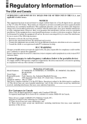
...FCC Rules. Operation is encouraged to try to correct the interference by the party responsible for a Class B digital device, pursuant to Part 15 of Industry Canada (IC). FCC WARNING Changes or modifications not expressly approved by one or more of the following two conditions: ...the user's authority to operate the equipment. These devices comply with Part 15 of Conformity Model Numbers: IT-3000M53E, IT-3000M54E2, IT-3000M55U, IT-3000M56U, HA-B61IO, HA-B30CHG Trade Name: CASIO Responsible party: Casio America, Inc. These limits are designed to provide reasonable protection ...
...FCC Rules. Operation is encouraged to try to correct the interference by the party responsible for a Class B digital device, pursuant to Part 15 of Industry Canada (IC). FCC WARNING Changes or modifications not expressly approved by one or more of the following two conditions: ...the user's authority to operate the equipment. These devices comply with Part 15 of Conformity Model Numbers: IT-3000M53E, IT-3000M54E2, IT-3000M55U, IT-3000M56U, HA-B61IO, HA-B30CHG Trade Name: CASIO Responsible party: Casio America, Inc. These limits are designed to provide reasonable protection ...
User Guide
Page 33
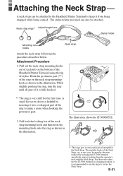
...while being carried. The rings give an extra mechanical strength for the first time. For those who often use the IT-3000 terminal in the illustration. Hook the protrusive part (**) of the ring on the bottom of the Handheld Printer Terminal using the tip of the neck strap mounting hook and...shown in a hanging position, it is recommended to use the rings to make a room when hooking the protrusive part. 2. E-31 A small flat screw driver is helpful by swinging the IT-3000 terminal specifically when it is very stiff for the Neck Strap. Pull back the locking bar of stylus. The ...
...while being carried. The rings give an extra mechanical strength for the first time. For those who often use the IT-3000 terminal in the illustration. Hook the protrusive part (**) of the ring on the bottom of the Handheld Printer Terminal using the tip of the neck strap mounting hook and...shown in a hanging position, it is recommended to use the rings to make a room when hooking the protrusive part. 2. E-31 A small flat screw driver is helpful by swinging the IT-3000 terminal specifically when it is very stiff for the Neck Strap. Pull back the locking bar of stylus. The ...
User Guide
Page 41
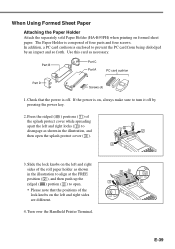
... FREE position ( 2 ), and then push up the ridged ( ) portion ( 2 ) to open. • Please note that the power is enclosed to disengage as necessary. Part B Part C Part A PC card cushion Part D Screws (4) 1. When Using Formed Sheet Paper Attaching the Paper Holder Attach the separately sold Paper Holder (HA-B93PH) when printing on the left and... apart the left and right locks ( 2 ) to prevent the PC card from being dislodged by pressing the power key. 2. Press the ridged ( ) portions ( 1 ) of four parts and four screws. Slide the lock knobs on formed sheet paper.
... FREE position ( 2 ), and then push up the ridged ( ) portion ( 2 ) to open. • Please note that the power is enclosed to disengage as necessary. Part B Part C Part A PC card cushion Part D Screws (4) 1. When Using Formed Sheet Paper Attaching the Paper Holder Attach the separately sold Paper Holder (HA-B93PH) when printing on the left and... apart the left and right locks ( 2 ) to prevent the PC card from being dislodged by pressing the power key. 2. Press the ridged ( ) portions ( 1 ) of four parts and four screws. Slide the lock knobs on formed sheet paper.
User Guide
Page 43
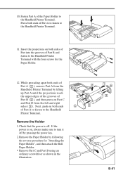
... Paper Holder", and then attach the Roll Paper Holder. • Remove Part C and Part D using an ordinary screwdriver as shown in the illustration. 1 D 3 E-41 Check that the power is on both ends C 3 of Part B and fasten to the Handheld Printer Terminal. Remove the Holder 1. Remove.... Insert the projections on , always make sure to turn it off . Next, push on Part C and Part D from the 2 Handheld Printer Terminal by pressing the power key. 2. Press both ends of Part A ( 1 ), remove Part A from the left and right sides ( 3 ). While spreading apart both ends of...
... Paper Holder", and then attach the Roll Paper Holder. • Remove Part C and Part D using an ordinary screwdriver as shown in the illustration. 1 D 3 E-41 Check that the power is on both ends C 3 of Part B and fasten to the Handheld Printer Terminal. Remove the Holder 1. Remove.... Insert the projections on , always make sure to turn it off . Next, push on Part C and Part D from the 2 Handheld Printer Terminal by pressing the power key. 2. Press both ends of Part A ( 1 ), remove Part A from the left and right sides ( 3 ). While spreading apart both ends of...
User Guide
Page 44
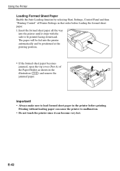
... paper. 1 2 1 Important! • Always make sure to be positioned at the printing position. • If the formed sheet paper becomes jammed, open the top cover (Part A) of Printer Settings in the printer before loading the formed sheet paper. 1. E-42
... paper. 1 2 1 Important! • Always make sure to be positioned at the printing position. • If the formed sheet paper becomes jammed, open the top cover (Part A) of Printer Settings in the printer before loading the formed sheet paper. 1. E-42
User Guide
Page 55
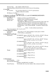
...: -20 to 50°C (5-35°C when printing on function available SD Memory Card Slot: SD Memory Card 9. printer part (All sizes exclude extruding parts.) Weight: IT-3000M53E Approx. 635g (22.4 oz) IT-3000M54E2 Approx. 680g (23.99 oz) IT-3000M55E/M55U Approx. ...PC Card Slot: PC Card Type I/Type II (3.3 V/5.0 V specifications) * Wake on 2-ply paper or labels) Humidity: 10-80% RH (no condensation) 12. display part, **; Magnetic Card Reader : ISO 7811 Tracks, 1, 2, and 3 (IT-3000M54E2/M55E/M55U) 10. Dimensions and Weight Dimensions: IT-3000M53E Approx. 80*/108** (W) ...
...: -20 to 50°C (5-35°C when printing on function available SD Memory Card Slot: SD Memory Card 9. printer part (All sizes exclude extruding parts.) Weight: IT-3000M53E Approx. 635g (22.4 oz) IT-3000M54E2 Approx. 680g (23.99 oz) IT-3000M55E/M55U Approx. ...PC Card Slot: PC Card Type I/Type II (3.3 V/5.0 V specifications) * Wake on 2-ply paper or labels) Humidity: 10-80% RH (no condensation) 12. display part, **; Magnetic Card Reader : ISO 7811 Tracks, 1, 2, and 3 (IT-3000M54E2/M55E/M55U) 10. Dimensions and Weight Dimensions: IT-3000M53E Approx. 80*/108** (W) ...
User Guide
Page 71
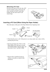
Check that the power is on the left side of the PC card removal tape. Part B Part C Part A PC card cushion Part D Screws (4) 1. Inserting a PC Card (When Using the Paper Holder) Check the names of the parts of the Paper Holder ( 1 ) and remove it off . Removing a PC Card Press the... eject button on , always make sure to turn it from the Handheld Printer Terminal ( 2 ), and then remove Part C and Part D ( 3 ). • Remove Part C and Part D using an ordinary screwdriver as shown by pressing the power key. 2. If the power is off by the arrow, and pull ...
Check that the power is on the left side of the PC card removal tape. Part B Part C Part A PC card cushion Part D Screws (4) 1. Inserting a PC Card (When Using the Paper Holder) Check the names of the parts of the Paper Holder ( 1 ) and remove it off . Removing a PC Card Press the... eject button on , always make sure to turn it from the Handheld Printer Terminal ( 2 ), and then remove Part C and Part D ( 3 ). • Remove Part C and Part D using an ordinary screwdriver as shown by pressing the power key. 2. If the power is off by the arrow, and pull ...
User Guide
Page 72
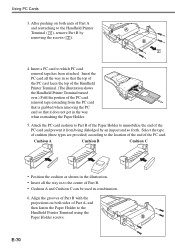
...Paper Holder. 5. Cushion A Cushion B Cushion C • Position the cushion as shown in the illustration. • Insert all the way in combination. 6. Align the grooves of Part B with the projections on both sides of the PC card removal tape extending from the PC card that is grabbed when removing the PC card... the Handheld Printer Terminal using the Paper Holder screws. Using PC Cards 3. E-70 Insert the PC card all the way in to the center of Part B. • Cushion A and Cushion C can be used in so that the top of the PC card faces the top of the Handheld Printer Terminal. ...
...Paper Holder. 5. Cushion A Cushion B Cushion C • Position the cushion as shown in the illustration. • Insert all the way in combination. 6. Align the grooves of Part B with the projections on both sides of the PC card removal tape extending from the PC card that is grabbed when removing the PC card... the Handheld Printer Terminal using the Paper Holder screws. Using PC Cards 3. E-70 Insert the PC card all the way in to the center of Part B. • Cushion A and Cushion C can be used in so that the top of the PC card faces the top of the Handheld Printer Terminal. ...
User Guide
Page 73
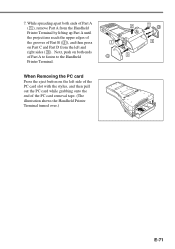
...card while grabbing onto the end of Part B ( 2 ), and then press on both ends of Part A ( 1 ), remove Part A from the left and right sides ( 3 ). While spreading apart both ends of Part A to fasten to the Handheld Printer Terminal. Next, push on Part C and Part D from the Handheld Printer Terminal ...by lifting up Part A until the projections reach the upper edges of the grooves of the PC card...
...card while grabbing onto the end of Part B ( 2 ), and then press on both ends of Part A ( 1 ), remove Part A from the left and right sides ( 3 ). While spreading apart both ends of Part A to fasten to the Handheld Printer Terminal. Next, push on Part C and Part D from the Handheld Printer Terminal ...by lifting up Part A until the projections reach the upper edges of the grooves of the PC card...