Service Manual
Page 6
...Self-Timer Mode 2.9 "Negative" Mode 2.10 Multi-image Mode 2.11 Erasing Images 2.12 Low Battery Indicator 2.13 CF Card Warning Indicator 2.14 Personal Computer Conniction Indicator 3. SPECIFICATIONS 4. CONTENTS Part 1 General Information 1. INTRODUCTION 1.1 Digital Imaging 1.2 High Image Quality 2. IC PIN CONNECTIONS 3. FILE SHARING WITH POWERSHOT 600 4.1 PowerShot... 600 Image Playback Restrictions 4.2 PowerShot 600 Image Playback Operation II 1-1 1-1 1-2 1-3 1-3 1-4 1-5 1-6 ...
...Self-Timer Mode 2.9 "Negative" Mode 2.10 Multi-image Mode 2.11 Erasing Images 2.12 Low Battery Indicator 2.13 CF Card Warning Indicator 2.14 Personal Computer Conniction Indicator 3. SPECIFICATIONS 4. CONTENTS Part 1 General Information 1. INTRODUCTION 1.1 Digital Imaging 1.2 High Image Quality 2. IC PIN CONNECTIONS 3. FILE SHARING WITH POWERSHOT 600 4.1 PowerShot... 600 Image Playback Restrictions 4.2 PowerShot 600 Image Playback Operation II 1-1 1-1 1-2 1-3 1-3 1-4 1-5 1-6 ...

Service Manual
Page 15
... O Flash O DC-IN Terminal 6V 9 ® Digital Terminal 0 Video Out Terminal O Lens 8 ▪ CF Card Slot O Battery Chamber Release Lever 7 9 0 0 O Flash Button 8 Self-timer Button • + & - Adjustment Buttons 3 +/- (Exposure Comp.) Button O W. BAL (White Balance) Button 0 Charging Lamp O Busy / Power Lamp O Erase Button • N/P Multi Button ® Date Button • ...
... O Flash O DC-IN Terminal 6V 9 ® Digital Terminal 0 Video Out Terminal O Lens 8 ▪ CF Card Slot O Battery Chamber Release Lever 7 9 0 0 O Flash Button 8 Self-timer Button • + & - Adjustment Buttons 3 +/- (Exposure Comp.) Button O W. BAL (White Balance) Button 0 Charging Lamp O Busy / Power Lamp O Erase Button • N/P Multi Button ® Date Button • ...
Service Manual
Page 18
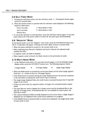
...power goes off . Last 2 seconds: Mark blinks at 2Hz. The N P indication will appear. In the Playback mode with a CF card with the self-timer mark displayed, the following sequence starts. 4 image display ▪ 16 image display single image display • When the Multi button is used . 1-8 ... the same. • In negative mode, the flash is disabled. • When negative mode is pressed while in mid-operation, press the self-timer button again, or turn the power switch off immediately. 2.9 "NEGATIVE" MODE In the Record mode, to the previously set the "Negative" color...
...power goes off . Last 2 seconds: Mark blinks at 2Hz. The N P indication will appear. In the Playback mode with a CF card with the self-timer mark displayed, the following sequence starts. 4 image display ▪ 16 image display single image display • When the Multi button is used . 1-8 ... the same. • In negative mode, the flash is disabled. • When negative mode is pressed while in mid-operation, press the self-timer button again, or turn the power switch off immediately. 2.9 "NEGATIVE" MODE In the Record mode, to the previously set the "Negative" color...
Service Manual
Page 22
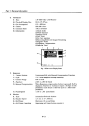
...Control Range 7.4 Aperture 7.5 Manual Compensation 7.6 Flash Speed 8. buttons to 1/1,000 sec. Shutter: 8.1 Type 8.2 Shutter Speed 8.3 Self Timer 8.4 Self Timer Canceling Programmed AE with Manual Compensation Function 'ITT, Center-weighted average metering Ev5 to Ev20 f/2.8 or f/8.0 (2 steps) When Exposure... 1/60 (Auto flash) Automatic electronic shutter 1/4 sec. to input ± 4 steps of compensation. Electronic 10 second delay Repressing self-timer button cancels it. 1-12 Use the +/- Part 1: General Information 6. Viewfinder 6.1 Type 6.2 Physical Display Size 6.3 Dot Arrangment ...
...Control Range 7.4 Aperture 7.5 Manual Compensation 7.6 Flash Speed 8. buttons to 1/1,000 sec. Shutter: 8.1 Type 8.2 Shutter Speed 8.3 Self Timer 8.4 Self Timer Canceling Programmed AE with Manual Compensation Function 'ITT, Center-weighted average metering Ev5 to Ev20 f/2.8 or f/8.0 (2 steps) When Exposure... 1/60 (Auto flash) Automatic electronic shutter 1/4 sec. to input ± 4 steps of compensation. Electronic 10 second delay Repressing self-timer button cancels it. 1-12 Use the +/- Part 1: General Information 6. Viewfinder 6.1 Type 6.2 Physical Display Size 6.3 Dot Arrangment ...

Service Manual
Page 44
... control I EEPROM R/B External Bus Wait command Power GND Not used External Clock crystal oscillator I Internal PLL Select (Fixed Low) Power GND O Not used GND Power 0 Self-timer LED O EVR LD O RTCLK CS O EEPROM CS Reset input Internal PLL Mode Select (Fixed Low) (Fixed Low) Operation Mode Select (Fixed High) Operation Mode Select...
... control I EEPROM R/B External Bus Wait command Power GND Not used External Clock crystal oscillator I Internal PLL Select (Fixed Low) Power GND O Not used GND Power 0 Self-timer LED O EVR LD O RTCLK CS O EEPROM CS Reset input Internal PLL Mode Select (Fixed Low) (Fixed Low) Operation Mode Select (Fixed High) Operation Mode Select...

Service Manual
Page 128
...)B0E1 R524 33 6523 ISO FP3003 5 V S3623A008 LC STI 2581218 R502 4700 'Mr STR TRG STBOK SLFLF 6 C 7 SHU (TER B 2 D501 820 LN28CAL OR504 03 EECSOHDW9)% (SELF TIMER LAMP) 0 0502 NJL7113B OPT. ADJ. 2 ENSOR) UN5217 (SWITCHING /STR.TRI.) R5051 5V R562 IC551 UPC393G2 I C552 C551 0.1 0.1 8561 R560 27K > 47K C554 4700 (COMPARATOR) B To...
...)B0E1 R524 33 6523 ISO FP3003 5 V S3623A008 LC STI 2581218 R502 4700 'Mr STR TRG STBOK SLFLF 6 C 7 SHU (TER B 2 D501 820 LN28CAL OR504 03 EECSOHDW9)% (SELF TIMER LAMP) 0 0502 NJL7113B OPT. ADJ. 2 ENSOR) UN5217 (SWITCHING /STR.TRI.) R5051 5V R562 IC551 UPC393G2 I C552 C551 0.1 0.1 8561 R560 27K > 47K C554 4700 (COMPARATOR) B To...
Service Manual
Page 129
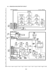
... NC SCK 7 RI j- DET.) 2 3 0 0.1 R2209 470 D2203 MA133 2 R2, CHG LED F (REVERSE) S2005 VSP1035 (FOWARD) S2008 VSP1035 2 3 2,70218 01 ) 02 O ' ( 03 D2005 LN1271RAL-TR (CHARGE) (SELF TIMER) S2006 VSP1035 2 3 52009 VSP1035 MO28 (DELETE) 02007 VSP1035 2 3 (FLASH S2010 VSP)1035 2 3 gA27238 (REC/PLAY) 02004 1N107W5PRW 2 4 RR 02 01 03 TT BATTERY CIRCUIT To...
... NC SCK 7 RI j- DET.) 2 3 0 0.1 R2209 470 D2203 MA133 2 R2, CHG LED F (REVERSE) S2005 VSP1035 (FOWARD) S2008 VSP1035 2 3 2,70218 01 ) 02 O ' ( 03 D2005 LN1271RAL-TR (CHARGE) (SELF TIMER) S2006 VSP1035 2 3 52009 VSP1035 MO28 (DELETE) 02007 VSP1035 2 3 (FLASH S2010 VSP)1035 2 3 gA27238 (REC/PLAY) 02004 1N107W5PRW 2 4 RR 02 01 03 TT BATTERY CIRCUIT To...


