Service Manual
Page 4
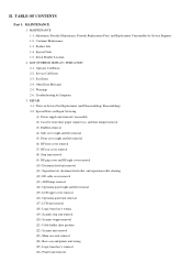
...Operation panel (right and left) removal (15) LCD upper cover removal (16) Operation panel unit removal (17) LCD unit removal (18) Logic board ass'y wiring (19) Scanner stop arm removal (20) Scanner stopper removal (21) Cable holder sheet position (22) Scanner unit removal (...23) Main case unit removal (24) Base case and printer unit wiring (25) Logic board ass'y removal (26) Printer unit removal Serial Number Location 2. Special Tools 1-5. Customer Maintenance 1-3. Service Call Errors 2-3. Product Life 1-4. Adjustment, ...
...Operation panel (right and left) removal (15) LCD upper cover removal (16) Operation panel unit removal (17) LCD unit removal (18) Logic board ass'y wiring (19) Scanner stop arm removal (20) Scanner stopper removal (21) Cable holder sheet position (22) Scanner unit removal (...23) Main case unit removal (24) Base case and printer unit wiring (25) Logic board ass'y removal (26) Printer unit removal Serial Number Location 2. Special Tools 1-5. Customer Maintenance 1-3. Service Call Errors 2-3. Product Life 1-4. Adjustment, ...
Service Manual
Page 5
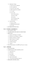
... Computer 3-4. Borderless Printing via Computer 3-3. CONNECTOR LOCATION AND PIN LAYOUT 2-1. NCU Board 2-3. PIXMA MP830 SPECIFICATIONS PRINT MODE 3-1. Normal Color Printing via Computer 3-5. FAQ (Problems Specific to the MP830 and Corrective Actions) Part 3: APPENDIX 1. Card Slot Board 2-5. NEW TECHNOLOGIES 2. Card Direct Printing 3-7. Operation Panel Board 2-6. CLEANING MODE AND AMOUNT OF INK PURGED 3. Duplex Printing via Computer 3-2. Camera...
... Computer 3-4. Borderless Printing via Computer 3-3. CONNECTOR LOCATION AND PIN LAYOUT 2-1. NCU Board 2-3. PIXMA MP830 SPECIFICATIONS PRINT MODE 3-1. Normal Color Printing via Computer 3-5. FAQ (Problems Specific to the MP830 and Corrective Actions) Part 3: APPENDIX 1. Card Slot Board 2-5. NEW TECHNOLOGIES 2. Card Direct Printing 3-7. Operation Panel Board 2-6. CLEANING MODE AND AMOUNT OF INK PURGED 3. Duplex Printing via Computer 3-2. Camera...
Service Manual
Page 7
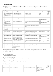
... replacement To adjust the belt tension. (Position the None. Grease application - At CL base or CL gear replacement - At logic board replacement - None. 1 min. None. At document feed base replacement To adjust the pressure sheet to fit in the service ...Replacement Parts, and Replacement Consumables by a service engineer. 1-2. Perform in the service mode. None. 2 min. Machine buttons - At logic board replacement To reset the waste ink counter. - Perform in the service mode. At carriage unit replacement To maintain detection functionality for the ...
... replacement To adjust the belt tension. (Position the None. Grease application - At CL base or CL gear replacement - At logic board replacement - None. 1 min. None. At document feed base replacement To adjust the pressure sheet to fit in the service ...Replacement Parts, and Replacement Consumables by a service engineer. 1-2. Perform in the service mode. None. 2 min. Machine buttons - At logic board replacement To reset the waste ink counter. - Perform in the service mode. At carriage unit replacement To maintain detection functionality for the ...
Service Manual
Page 12
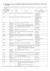
... - PR lift shaft - Carriage lift sensor unit 12 times AP position error [6A00] An error occurred in the ASF cam sensor. - Logic board error - Logic board 20 times Other hardware [6500] The PCI bus error is not proper. - Scanner unit Continuous alternate ROM error [6100] The check sum...6 times Internal temperature error [5400] The internal temperature is detected by the number of listed parts, which are indicated by the ASIC. Logic board 22 times Scanner error [5010] The scanner unit cannot detect the home position, or the scanner unit warming-up or down properly. -...
... - PR lift shaft - Carriage lift sensor unit 12 times AP position error [6A00] An error occurred in the ASF cam sensor. - Logic board error - Logic board 20 times Other hardware [6500] The PCI bus error is not proper. - Scanner unit Continuous alternate ROM error [6100] The check sum...6 times Internal temperature error [5400] The internal temperature is detected by the number of listed parts, which are indicated by the ASIC. Logic board 22 times Scanner error [5010] The scanner unit cannot detect the home position, or the scanner unit warming-up or down properly. -...
Service Manual
Page 13
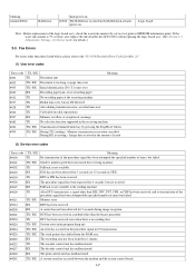
... ##238 RX The print control unit has malfunctioned. ##261 TX / RX A system error has occurred between the modem and the system control board. 1-7 blinking Alarm LED lit RAM error hard-power-on . - Fax Errors For errors other than the binary procedure. ##204 TX DTC has...not received. ##107 RX Fallback is 7% or more, also replace the ink absorber kit (QY5-0153) when replacing the logic board ass'y. [See Section 3-3. Logic board Note: Before replacement of the logic board ass'y, check the waste ink amount (by pressing the Stop/Reset button #995 TX / RX During TX (sending): ...
... ##238 RX The print control unit has malfunctioned. ##261 TX / RX A system error has occurred between the modem and the system control board. 1-7 blinking Alarm LED lit RAM error hard-power-on . - Fax Errors For errors other than the binary procedure. ##204 TX DTC has...not received. ##107 RX Fallback is 7% or more, also replace the ink absorber kit (QY5-0153) when replacing the logic board ass'y. [See Section 3-3. Logic board Note: Before replacement of the logic board ass'y, check the waste ink amount (by pressing the Stop/Reset button #995 TX / RX During TX (sending): ...
Service Manual
Page 17
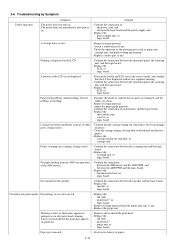
...of - Confirm the connection of paper. 1-11 Nothing is free from the speaker. - Replace the - Remove foreign material. - logic board. logic board. 2-6. Paper feed problems (multi-feeding, skewed feeding, no scanning, strange noise). - Confirm the connection between the ADF motor and ...no parts are damaged, and the rollers are clean. - Remove foreign material. - Check the operation of each harness and the logic board. - logic board. Confirm that no color ejected. - Replace the - A portion of the ADF motor). - No sound from damage or ...
...of - Confirm the connection of paper. 1-11 Nothing is free from the speaker. - Replace the - Remove foreign material. - logic board. logic board. 2-6. Paper feed problems (multi-feeding, skewed feeding, no scanning, strange noise). - Confirm the connection between the ADF motor and ...no parts are damaged, and the rollers are clean. - Remove foreign material. - Check the operation of each harness and the logic board. - logic board. Confirm that no color ejected. - Replace the - A portion of the ADF motor). - No sound from damage or ...
Service Manual
Page 18
...paper path with cotton swab or cloth. - Color hue is incorrect. Replace the - No scanning. - between the scanning unit and the logic board. - logic board. No ejection of the ADF motor). - ink tank, or - Graphic or text is performed 2 times, and when the problem persists...ink tank, or - Confirm the connection between the ADF motor and the ADF PWB, and - timing slit disk film, - Replace the - logic board. scanning unit, or - scanning unit, - Faulty scanning - When enlarged in the paper feed direction: - Clean the platen glass and the ADF...
...paper path with cotton swab or cloth. - Color hue is incorrect. Replace the - No scanning. - between the scanning unit and the logic board. - logic board. No ejection of the ADF motor). - ink tank, or - Graphic or text is performed 2 times, and when the problem persists...ink tank, or - Confirm the connection between the ADF motor and the ADF PWB, and - timing slit disk film, - Replace the - logic board. scanning unit, or - scanning unit, - Faulty scanning - When enlarged in the paper feed direction: - Clean the platen glass and the ADF...
Service Manual
Page 22
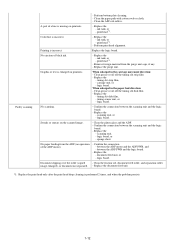
...print head alignment sensors. 5. Adjustment / Settings, (6) Service mode, for details.] [See 3-3. REPAIR 3-1. Service test print - Apply grease to the logic board ass'y. 3. Correct the CD / DVD and automatic print head alignment sensors. [See 3.3. Upon contact with ethanol. 1. Service test print, or (2) ...EEPROM 6. Copy - Perform the print head alignment in the discharge of the logic board After replacement: ass'y, remove the power cord, and 1. Perform the print head alignment in the user mode. Service test print...
...print head alignment sensors. 5. Adjustment / Settings, (6) Service mode, for details.] [See 3-3. REPAIR 3-1. Service test print - Apply grease to the logic board ass'y. 3. Correct the CD / DVD and automatic print head alignment sensors. [See 3.3. Upon contact with ethanol. 1. Service test print, or (2) ...EEPROM 6. Copy - Perform the print head alignment in the discharge of the logic board After replacement: ass'y, remove the power cord, and 1. Perform the print head alignment in the user mode. Service test print...

Service Manual
Page 24
Protect the housing from soiled with the red screws, as follows: i. ii. Protect electrical parts from damage due to protect the logic board ass'y from damages). - Do not touch the timing slit strip film and timing slit disk film. Protect the units from scratches. - The red screws of ...
Protect the housing from soiled with the red screws, as follows: i. ii. Protect electrical parts from damage due to protect the logic board ass'y from damages). - Do not touch the timing slit strip film and timing slit disk film. Protect the units from scratches. - The red screws of ...
Service Manual
Page 34
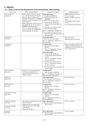
(16) Operation panel unit removal - Remove the screw and disconnect the flat cable. (18) Logic board ass'y wiring 1-28 Remove the 4 screws. - Remove the flat cable. (17) LCD unit removal -
(16) Operation panel unit removal - Remove the screw and disconnect the flat cable. (18) Logic board ass'y wiring 1-28 Remove the 4 screws. - Remove the flat cable. (17) LCD unit removal -
Service Manual
Page 36
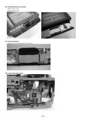
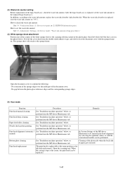
(20) Scanner stopper removal - On the logic board, remove the flat cables from CN702. - The cable holder sheet is attached to the scanner unit, slide the stopper in the direction indicated by the ... the stopper perpendicular to the prescribed location with double-sided adhesive tape. (22) Scanner unit removal - Remove the ground wire and core. 1-30 On the logic board, remove the harness from CN801 and CN802, then remove 2 screws. - On the logic board, remove the flat cable from the scanner unit. (21) Cable holder sheet position -
(20) Scanner stopper removal - On the logic board, remove the flat cables from CN702. - The cable holder sheet is attached to the scanner unit, slide the stopper in the direction indicated by the ... the stopper perpendicular to the prescribed location with double-sided adhesive tape. (22) Scanner unit removal - Remove the ground wire and core. 1-30 On the logic board, remove the harness from CN801 and CN802, then remove 2 screws. - On the logic board, remove the flat cable from the scanner unit. (21) Cable holder sheet position -
Service Manual
Page 42
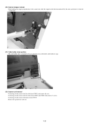
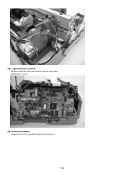
Remove all the flat cables and harnesses from the logic board. - Remove the 7 screws. (26) Printer unit removal - Remove the 4 screws, and lift the printer unit to remove it. 1-36 (25) Logic board ass'y removal -
Remove all the flat cables and harnesses from the logic board. - Remove the 7 screws. (26) Printer unit removal - Remove the 4 screws, and lift the printer unit to remove it. 1-36 (25) Logic board ass'y removal -
Service Manual
Page 47
... Adjustment / Settings, (6) Service mode, "Waste ink amount setting procedures." (4) White sponge sheet attachment Position one of the corners of the logic board ass'y, check the waste ink amount. Nozzle check pattern printing See "Standalone machine operation" below , or perform from the MP driver Maintenance tab...Cleaning of the platen ribs when the back side of the document cover. - After the logic board ass'y is replaced, reset the waste ink counter (to the replaced logic board ass'y. No gap between the platen glass reference edges and the corresponding sponge edges. (5) User...
... Adjustment / Settings, (6) Service mode, "Waste ink amount setting procedures." (4) White sponge sheet attachment Position one of the corners of the logic board ass'y, check the waste ink amount. Nozzle check pattern printing See "Standalone machine operation" below , or perform from the MP driver Maintenance tab...Cleaning of the platen ribs when the back side of the document cover. - After the logic board ass'y is replaced, reset the waste ink counter (to the replaced logic board ass'y. No gap between the platen glass reference edges and the corresponding sponge edges. (5) User...
Service Manual
Page 50
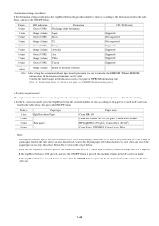
...Canon HR-101 is pressed, the Alarm LED and the COPY button light alternately, Alarm in orange and COPY in green. - Each time the Stop/Reset button is used at the production site), but 6 kinds of times according to the paper to the menu selection Note: After setting the destination without logic board... table below . - Verification Items, (1) Service test print, or (2) EEPROM information print.] After replacement of the feed roller ass'y or logic board ass'y in repair servicing or in refurbishment operation, adjust the line feeding. 1) In the LF correction mode, press the Stop/Reset button...
...Canon HR-101 is pressed, the Alarm LED and the COPY button light alternately, Alarm in orange and COPY in green. - Each time the Stop/Reset button is used at the production site), but 6 kinds of times according to the paper to the menu selection Note: After setting the destination without logic board... table below . - Verification Items, (1) Service test print, or (2) EEPROM information print.] After replacement of the feed roller ass'y or logic board ass'y in repair servicing or in refurbishment operation, adjust the line feeding. 1) In the LF correction mode, press the Stop/Reset button...

Service Manual
Page 52
...(s) according to the waste ink absorber whose value should be transferred to the replaced new EEPROM. (Only the main waste ink absorber for the MP830) Time(s) Waste ink absorber Remarks 0 times Main waste ink absorber 1 time Platen waste ink absorber Not valid for the... amount. 4) The LF correction value is written to the EEPROM, and the machine returns to a replaced new EEPROM after the logic board is replaced in servicing. 1) Before replacement of the logic board ass'y, check the waste ink amount in EEPROM information print. [See 3-4. Set the waste ink amount data to the service mode...
...(s) according to the waste ink absorber whose value should be transferred to the replaced new EEPROM. (Only the main waste ink absorber for the MP830) Time(s) Waste ink absorber Remarks 0 times Main waste ink absorber 1 time Platen waste ink absorber Not valid for the... amount. 4) The LF correction value is written to the EEPROM, and the machine returns to a replaced new EEPROM after the logic board is replaced in servicing. 1) Before replacement of the logic board ass'y, check the waste ink amount in EEPROM information print. [See 3-4. Set the waste ink amount data to the service mode...


