Service Manual
Page 5
...Controlling the Intensity of Copyboard 1. Scanning System 3-10 3. Turning the Scanning Lamp COPYRIGHT © 1998 CANON INC. External View 1-4 B. Control Panel 1-6 1. Replacing the Cartridge ........1-11 1. Main Motor Control Circuit ......2-5 1. Outputs from DC Controller (1/2 2-8 2. Mechanism of ... Cover 1-14 2. FEATURES 1-1 II. Cross Section 1-5 IV. PC420/430/FC220 1-6 2. Making Copies 1-8 C. Jam Indicator 1-11 D. Time to DC Controller ...........2-6 1. Replacing the Cartridge ...1-12 F. Cleaning 1-14 1. When Not Using the Copier for ...
...Controlling the Intensity of Copyboard 1. Scanning System 3-10 3. Turning the Scanning Lamp COPYRIGHT © 1998 CANON INC. External View 1-4 B. Control Panel 1-6 1. Replacing the Cartridge ........1-11 1. Main Motor Control Circuit ......2-5 1. Outputs from DC Controller (1/2 2-8 2. Mechanism of ... Cover 1-14 2. FEATURES 1-1 II. Cross Section 1-5 IV. PC420/430/FC220 1-6 2. Making Copies 1-8 C. Jam Indicator 1-11 D. Time to DC Controller ...........2-6 1. Replacing the Cartridge ...1-12 F. Cleaning 1-14 1. When Not Using the Copier for ...
Service Manual
Page 6
...Operations 4-8 E. MECHANICAL SYSTEM............5-10 A. OUTLINE OF OPERATIONS .......6-1 A. Controlling the Fixing Heater Temperature 6-3 C. Fixing Assembly 6-7 iv COPYRIGHT © 1998 CANON INC. CANON PC400/420/430,FC200/220 REV.0 JAN.1998 PRINTED IN JAPAN (IMPRIME AU JAPON) Detaching the Transfer Charging Roller 4-20 CHAPTER 5 PICK-UP/FEEDING SYSTEM I ....4-6 2. Pick-Up/Feeding Timing Chart (A4, 2 copies 5-5 IV. PC400/FC200 5-6 B. Detaching the Pick-Up Roller 5-11 B. PC420/430/FC220 5-6 2. Outline 4-1 B. Operations 4-11 F. Cartridge 4-17 1.
...Operations 4-8 E. MECHANICAL SYSTEM............5-10 A. OUTLINE OF OPERATIONS .......6-1 A. Controlling the Fixing Heater Temperature 6-3 C. Fixing Assembly 6-7 iv COPYRIGHT © 1998 CANON INC. CANON PC400/420/430,FC200/220 REV.0 JAN.1998 PRINTED IN JAPAN (IMPRIME AU JAPON) Detaching the Transfer Charging Roller 4-20 CHAPTER 5 PICK-UP/FEEDING SYSTEM I ....4-6 2. Pick-Up/Feeding Timing Chart (A4, 2 copies 5-5 IV. PC400/FC200 5-6 B. Detaching the Pick-Up Roller 5-11 B. PC420/430/FC220 5-6 2. Outline 4-1 B. Operations 4-11 F. Cartridge 4-17 1.
Service Manual
Page 7
... I . Detaching the Bottom Cover 7-8 B. Detaching the Copyboard Cover 7-9 2. UNPACKING AND INSTALLATION 8-2 III. Storing Unsealed Cartridges 9-3 2. CANON PC400/420/430,FC200/220 REV.0 JAN.1998 PRINTED IN JAPAN (IMPRIME AU JAPON) v Protection Mechanism for Power Supply Circuit 7-2 II.... 1. RELOCATING THE MACHINE ....8-5 CHAPTER 9 MAINTENANCE AND SERVICING I . Storing and Handling Unsealed Cartridges 9-3 1. Image Leading Edge Margin COPYRIGHT © 1998 CANON INC. External Covers 7-4 1. SELECTING THE SITE 8-1 II. DURABLES 9-1 III. 1. Removing the Fixing Upper Unit...
... I . Detaching the Bottom Cover 7-8 B. Detaching the Copyboard Cover 7-9 2. UNPACKING AND INSTALLATION 8-2 III. Storing Unsealed Cartridges 9-3 2. CANON PC400/420/430,FC200/220 REV.0 JAN.1998 PRINTED IN JAPAN (IMPRIME AU JAPON) v Protection Mechanism for Power Supply Circuit 7-2 II.... 1. RELOCATING THE MACHINE ....8-5 CHAPTER 9 MAINTENANCE AND SERVICING I . Storing and Handling Unsealed Cartridges 9-3 1. Image Leading Edge Margin COPYRIGHT © 1998 CANON INC. External Covers 7-4 1. SELECTING THE SITE 8-1 II. DURABLES 9-1 III. 1. Removing the Fixing Upper Unit...
Service Manual
Page 11
... 1-1 II. When Not Using the Copier for a Long Time 1-16 V. IMAGE FORMATION 1-17 A. I. NAMES OF PARTS 1-4 A. External View 1-4 B. Making Copies 1-8 C. Outline 1-17 COPYRIGHT © 1998 CANON INC. SPECIFICATIONS 1-2 III. Control Panel 1-6 B. Replacing the Cartridge ........1-11 F. Jam Indicator 1-11 D. Cleaning 1-14 H. Changing the Density ...........1-14 G. Add Paper Indicator 1-11 E. Cross Section 1-5 IV. OPERATION...
... 1-1 II. When Not Using the Copier for a Long Time 1-16 V. IMAGE FORMATION 1-17 A. I. NAMES OF PARTS 1-4 A. External View 1-4 B. Making Copies 1-8 C. Outline 1-17 COPYRIGHT © 1998 CANON INC. SPECIFICATIONS 1-2 III. Control Panel 1-6 B. Replacing the Cartridge ........1-11 F. Jam Indicator 1-11 D. Cleaning 1-14 H. Changing the Density ...........1-14 G. Add Paper Indicator 1-11 E. Cross Section 1-5 IV. OPERATION...
Service Manual
Page 13
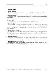
...be placed on the Copy Start key is compact and light, providing good portability. The copier shuts off . Cartridge type. COPYRIGHT © 1998 CANON INC. The charging roller directly charges paper, significantly reducing ozone emission. 2. The copier's wait time is integrated into a ...CHAPTER 1 GENERAL DESCRIPTION I. The user need no more than replace the cartridge and perform simple cleaning to generate multiple copies. In addition to black toner, the user has a choice of copy effects. CANON PC400/420/430,FC200/220 REV.0 JAN.1998 PRINTED IN JAPAN (IMPRIME AU JAPON) ...
...be placed on the Copy Start key is compact and light, providing good portability. The copier shuts off . Cartridge type. COPYRIGHT © 1998 CANON INC. The charging roller directly charges paper, significantly reducing ozone emission. 2. The copier's wait time is integrated into a ...CHAPTER 1 GENERAL DESCRIPTION I. The user need no more than replace the cartridge and perform simple cleaning to generate multiple copies. In addition to black toner, the user has a choice of copy effects. CANON PC400/420/430,FC200/220 REV.0 JAN.1998 PRINTED IN JAPAN (IMPRIME AU JAPON) ...

Service Manual
Page 15
... Depth 15.7 in./402 mm Height 4.1 in./108 mm Weight (including cartridge) 16.6 lb/7.4 kg (approx.) Copy paper Consumables Cartridge Keep wrapped to change without notice. Specifications subject to protect against humidity. See CHAPTER 9. Others COPYRIGHT © 1998 CANON INC. CANON PC400/420/430,FC200/220 REV.0 JAN.1998 PRINTED IN JAPAN (IMPRIME AU JAPON...
... Depth 15.7 in./402 mm Height 4.1 in./108 mm Weight (including cartridge) 16.6 lb/7.4 kg (approx.) Copy paper Consumables Cartridge Keep wrapped to change without notice. Specifications subject to protect against humidity. See CHAPTER 9. Others COPYRIGHT © 1998 CANON INC. CANON PC400/420/430,FC200/220 REV.0 JAN.1998 PRINTED IN JAPAN (IMPRIME AU JAPON...
Service Manual
Page 16
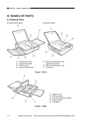
CANON PC400/420/430,FC200/220 REV.0 JAN.1998 PRINTED IN JAPAN (IMPRIME AU JAPON) External View (PC420/430/FC220) Œ (PC400/FC200) Œ Ž Ž ’ ‘ q Copyboard cover w Copyboard glass e Pick-up tray r Open/Close button ‘ ... open/close button y Delivery assembly cover u Copy tray Figure 1-301A Œ Ž q Upper cover w Pick-up guide e Density correction switch r Power switch t Cartridge Figure 1-302A 1-4 COPYRIGHT © 1998 CANON INC. NAMES OF PARTS A. CHAPTER 1 GENERAL DESCRIPTION III.
CANON PC400/420/430,FC200/220 REV.0 JAN.1998 PRINTED IN JAPAN (IMPRIME AU JAPON) External View (PC420/430/FC220) Œ (PC400/FC200) Œ Ž Ž ’ ‘ q Copyboard cover w Copyboard glass e Pick-up tray r Open/Close button ‘ ... open/close button y Delivery assembly cover u Copy tray Figure 1-301A Œ Ž q Upper cover w Pick-up guide e Density correction switch r Power switch t Cartridge Figure 1-302A 1-4 COPYRIGHT © 1998 CANON INC. NAMES OF PARTS A. CHAPTER 1 GENERAL DESCRIPTION III.

Service Manual
Page 22
.... • Do not process each side more than three times. 1-10 COPYRIGHT © 1998 CANON INC. CANON PC400/420/430,FC200/220 REV.0 JAN.1998 PRINTED IN JAPAN (IMPRIME AU JAPON) or three-colored copies by replacing the cartridge. • Use paper of 64 to return. Figure 1-405B Making Overlay Copies You can make...
.... • Do not process each side more than three times. 1-10 COPYRIGHT © 1998 CANON INC. CANON PC400/420/430,FC200/220 REV.0 JAN.1998 PRINTED IN JAPAN (IMPRIME AU JAPON) or three-colored copies by replacing the cartridge. • Use paper of 64 to return. Figure 1-405B Making Overlay Copies You can make...

Service Manual
Page 23
...1-401E). then, detach the paper from the delivery cover, and pull it ; D. Replacing the Cartridge 1. then, move the copyboard to tear the paper when removing it slowly in the pick-up or...out slowly through the opening of copies are made. Figure 1-401E COPYRIGHT © 1998 CANON INC. Add Paper Indicator PC420/430/FC220 ' ' flashes if you try to make a copy when the pick-up ... jam is in the direction of toner, copies tend to Replace the Cartridge When the cartridge is on the tray, place paper. CANON PC400/420/430,FC200/220 REV.0 JAN.1998 PRINTED IN JAPAN (IMPRIME AU JAPON)...
...1-401E). then, detach the paper from the delivery cover, and pull it ; D. Replacing the Cartridge 1. then, move the copyboard to tear the paper when removing it slowly in the pick-up or...out slowly through the opening of copies are made. Figure 1-401E COPYRIGHT © 1998 CANON INC. Add Paper Indicator PC420/430/FC220 ' ' flashes if you try to make a copy when the pick-up ... jam is in the direction of toner, copies tend to Replace the Cartridge When the cartridge is on the tray, place paper. CANON PC400/420/430,FC200/220 REV.0 JAN.1998 PRINTED IN JAPAN (IMPRIME AU JAPON)...

Service Manual
Page 24
... return to normal, • Replace the cartridge as shown in Figure 1-402E. CANON PC400/420/430,FC200/220 REV.0 JAN.1998 PRINTED IN JAPAN (IMPRIME AU JAPON) Figure 1-402E 2) Set the cartridge back in both directions. b. Replacing the Cartridge 1) Move the copyboard to open the top cover. 2) Slide the cartridge out of the copier. 3) Hold the...
... return to normal, • Replace the cartridge as shown in Figure 1-402E. CANON PC400/420/430,FC200/220 REV.0 JAN.1998 PRINTED IN JAPAN (IMPRIME AU JAPON) Figure 1-402E 2) Set the cartridge back in both directions. b. Replacing the Cartridge 1) Move the copyboard to open the top cover. 2) Slide the cartridge out of the copier. 3) Hold the...
Service Manual
Page 25
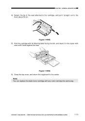
CHAPTER 1 GENERAL DESCRIPTION 4) Detach the tip of the seal attached to the cartridge, and pull it in the copier with any color cartridge the same way. Note: You can replace the black toner cartridge with care until it butts against the rear. Figure 1-405E 6) Close the top cover, and return the copyboard to the front; about 50 cm. CANON PC400/420/430,FC200/220 REV.0 JAN.1998 PRINTED IN JAPAN (IMPRIME AU JAPON) 1-13 Figure 1-404E 5) Hold the cartridge with its Warning label facing the left, and insert it straight out to the center. COPYRIGHT © 1998 CANON INC.
CHAPTER 1 GENERAL DESCRIPTION 4) Detach the tip of the seal attached to the cartridge, and pull it in the copier with any color cartridge the same way. Note: You can replace the black toner cartridge with care until it butts against the rear. Figure 1-405E 6) Close the top cover, and return the copyboard to the front; about 50 cm. CANON PC400/420/430,FC200/220 REV.0 JAN.1998 PRINTED IN JAPAN (IMPRIME AU JAPON) 1-13 Figure 1-404E 5) Hold the cartridge with its Warning label facing the left, and insert it straight out to the center. COPYRIGHT © 1998 CANON INC.

Service Manual
Page 27
CANON PC400/420/430,FC200/220 REV.0 JAN.1998 PRINTED IN JAPAN (IMPRIME AU JAPON) 1-15 Fiber lens (face side) Figure 1-401G 3) Open the upper cover, and remove the cartridge. 4) Put a flat-tipped cotton wad in the lens array groove, and move it back and forth lightly. Figure 1-402G COPYRIGHT © 1998 CANON INC. CHAPTER 1 GENERAL DESCRIPTION 2. Lens Array 1) Move the copyboard to the left until it stops. 2) Put a cotton wad in the lens array (rear) groove, and move it back and forth.
CANON PC400/420/430,FC200/220 REV.0 JAN.1998 PRINTED IN JAPAN (IMPRIME AU JAPON) 1-15 Fiber lens (face side) Figure 1-401G 3) Open the upper cover, and remove the cartridge. 4) Put a flat-tipped cotton wad in the lens array groove, and move it back and forth lightly. Figure 1-402G COPYRIGHT © 1998 CANON INC. CHAPTER 1 GENERAL DESCRIPTION 2. Lens Array 1) Move the copyboard to the left until it stops. 2) Put a cotton wad in the lens array (rear) groove, and move it back and forth.

Service Manual
Page 55
... out the fixing assembly. 2) Remove the screw and remove the grounding wire q; then, disconnect the four connectors e. 3) Remove the screw r, and detach the cartridge support t. B. CANON PC400/420/430,FC200/220 REV.0 JAN.1998 PRINTED IN JAPAN (IMPRIME AU JAPON) 3-11 Copyboard Drive Assembly 1. remove the screw, and remove the motor rotation detecting...; Note: Take extra care not to damage the teeth of the gear when lifting the copyboard drive assembly. (rear) Figure 3-302B COPYRIGHT © 1998 CANON INC.
... out the fixing assembly. 2) Remove the screw and remove the grounding wire q; then, disconnect the four connectors e. 3) Remove the screw r, and detach the cartridge support t. B. CANON PC400/420/430,FC200/220 REV.0 JAN.1998 PRINTED IN JAPAN (IMPRIME AU JAPON) 3-11 Copyboard Drive Assembly 1. remove the screw, and remove the motor rotation detecting...; Note: Take extra care not to damage the teeth of the gear when lifting the copyboard drive assembly. (rear) Figure 3-302B COPYRIGHT © 1998 CANON INC.

Service Manual
Page 57
Outline 4-1 B. Primary Charging Control Circuit 4-3 D. Cartridge 4-17 III. Photosensitive Drum 4-19 B. Transfer Charging Roller.......4-20 COPYRIGHT © 1998 CANON INC. PC420/430/FC220).......4-14 II. CANON PC400/420/430,FC200/220 REV.0 JAN.1998 PRINTED IN JAPAN (IMPRIME AU JAPON) 1 Sequence of respective parts. Controlling Developing Bias....4-6 E. CHARGING, DEVELOPING, AND CLEANING SYSTEMS 4-17 A. Transfer ...
Outline 4-1 B. Primary Charging Control Circuit 4-3 D. Cartridge 4-17 III. Photosensitive Drum 4-19 B. Transfer Charging Roller.......4-20 COPYRIGHT © 1998 CANON INC. PC420/430/FC220).......4-14 II. CANON PC400/420/430,FC200/220 REV.0 JAN.1998 PRINTED IN JAPAN (IMPRIME AU JAPON) 1 Sequence of respective parts. Controlling Developing Bias....4-6 E. CHARGING, DEVELOPING, AND CLEANING SYSTEMS 4-17 A. Transfer ...

Service Manual
Page 75
...-blocking shutter Photosensitive drum Cleaning blade Drum cover shutter Developing cylinder Figure 4-201A a. CHPTER 4 IMAGE FORMATION SYSTEM II. CANON PC400/420/430,FC200/220 REV.0 JAN.1998 PRINTED IN JAPAN (IMPRIME AU JAPON) 4-17 Cartridge 1. if exposed to open the drum cover shutter unless it will develop residual memory, causing white spots or...
...-blocking shutter Photosensitive drum Cleaning blade Drum cover shutter Developing cylinder Figure 4-201A a. CHPTER 4 IMAGE FORMATION SYSTEM II. CANON PC400/420/430,FC200/220 REV.0 JAN.1998 PRINTED IN JAPAN (IMPRIME AU JAPON) 4-17 Cartridge 1. if exposed to open the drum cover shutter unless it will develop residual memory, causing white spots or...

Service Manual
Page 77
... direction it rotates for making copies; You must try to an intensity of 1500 lux (about 10000 and 30000 lux.) COPYRIGHT © 1998 CANON INC. CANON PC400/420/430,FC200/220 REV.0 JAN.1998 PRINTED IN JAPAN (IMPRIME AU JAPON) 4-19 Caution: 1. Cleaning the Drum Caution: As a rule, do... not use paper, lint-free or otherwise. 3. do not touch or clean the photosensitive drum. 1) Open the top cover, and take out the cartridge. 2) Put the cartridge ...
... direction it rotates for making copies; You must try to an intensity of 1500 lux (about 10000 and 30000 lux.) COPYRIGHT © 1998 CANON INC. CANON PC400/420/430,FC200/220 REV.0 JAN.1998 PRINTED IN JAPAN (IMPRIME AU JAPON) 4-19 Caution: 1. Cleaning the Drum Caution: As a rule, do... not use paper, lint-free or otherwise. 3. do not touch or clean the photosensitive drum. 1) Open the top cover, and take out the cartridge. 2) Put the cartridge ...
Service Manual
Page 78
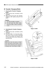
...; Figure 4-301B Hook Spring Hook Boss Figure 4-302B 4-20 COPYRIGHT © 1998 CANON INC. Do not touch the roller; at this time, remove the spring as well. Caution: 1. CANON PC400/420/430,FC200/220 REV.0 JAN.1998 PRINTED IN JAPAN (IMPRIME AU JAPON) Detaching the Transfer Charging Roller... 1) Open the top cover, and take out the cartridge. 2) Free the tabs q of solvent or oil. 2. Transfer ...
...; Figure 4-301B Hook Spring Hook Boss Figure 4-302B 4-20 COPYRIGHT © 1998 CANON INC. Do not touch the roller; at this time, remove the spring as well. Caution: 1. CANON PC400/420/430,FC200/220 REV.0 JAN.1998 PRINTED IN JAPAN (IMPRIME AU JAPON) Detaching the Transfer Charging Roller... 1) Open the top cover, and take out the cartridge. 2) Free the tabs q of solvent or oil. 2. Transfer ...

Service Manual
Page 117
CANON PC400/420/430,FC200/220 REV.0 JAN.1998 PRINTED IN JAPAN (IMPRIME AU JAPON) 7-5 Detaching the Body Cover 1) Detach the copyboard. Œ 2) Detach the two cover plates q by pulling them up. 3) Detach the pick-up tray and delivery tray. 4) Detach the control cover. 5) Open the top cover, and take out the cartridge. 6) Press... hole e in the body cover w with a screwdriver, and lift the body cover slightly. Œ Figure 7-203A Ž Figure 7-204A (right view) COPYRIGHT © 1998 CANON INC. CHAPTER 7 EXTERNALS/AUXILIARY MECHANISMS 2.
CANON PC400/420/430,FC200/220 REV.0 JAN.1998 PRINTED IN JAPAN (IMPRIME AU JAPON) 7-5 Detaching the Body Cover 1) Detach the copyboard. Œ 2) Detach the two cover plates q by pulling them up. 3) Detach the pick-up tray and delivery tray. 4) Detach the control cover. 5) Open the top cover, and take out the cartridge. 6) Press... hole e in the body cover w with a screwdriver, and lift the body cover slightly. Œ Figure 7-203A Ž Figure 7-204A (right view) COPYRIGHT © 1998 CANON INC. CHAPTER 7 EXTERNALS/AUXILIARY MECHANISMS 2.

Service Manual
Page 130
If any such problem is installed in the copier, pull it . Cardboard Cardboard 6 Take out the cartridge from the bag. (If the cartridge is expected, leave the copier alone at the site of installation at either end of the charging roller, straight up and out of the copier... 1 Open the shipping carton. 2 Take out the accessories. The phenomenon is in the copier can cause droplets of tape that hold during transit. CANON PC400/420/430,FC200/220 REV.0 JAN.1998 PRINTED IN JAPAN (IMPRIME AU JAPON) Make sure that the Operator's Manual is known as condensation, and condensation in...
If any such problem is installed in the copier, pull it . Cardboard Cardboard 6 Take out the cartridge from the bag. (If the cartridge is expected, leave the copier alone at the site of installation at either end of the charging roller, straight up and out of the copier... 1 Open the shipping carton. 2 Take out the accessories. The phenomenon is in the copier can cause droplets of tape that hold during transit. CANON PC400/420/430,FC200/220 REV.0 JAN.1998 PRINTED IN JAPAN (IMPRIME AU JAPON) Make sure that the Operator's Manual is known as condensation, and condensation in...

Service Manual
Page 131
CHAPTER 8 INSTALLATION Description COPYRIGHT © 1998 CANON INC. then, detach the tip of the seal, and pull it fully out (about 90°. 8 Place the cartridge on a level place; CANON PC400/420/430,FC200/220 REV.0 JAN.1998 PRINTED IN JAPAN (IMPRIME AU JAPON) 8-3 Step Work 7 Hold the cartridge with its Warning label facing left, and slide in the cartridge slowly until it stops. 10 Close the top cover, and return it in both directions about 50 cm). 9 Hold the cartridge with its Warning label facing up, and rotate it to the center.
CHAPTER 8 INSTALLATION Description COPYRIGHT © 1998 CANON INC. then, detach the tip of the seal, and pull it fully out (about 90°. 8 Place the cartridge on a level place; CANON PC400/420/430,FC200/220 REV.0 JAN.1998 PRINTED IN JAPAN (IMPRIME AU JAPON) 8-3 Step Work 7 Hold the cartridge with its Warning label facing left, and slide in the cartridge slowly until it stops. 10 Close the top cover, and return it in both directions about 50 cm). 9 Hold the cartridge with its Warning label facing up, and rotate it to the center.


