

Service Manual
Page 4
..., '1' is used to indicate that the voltage level of a given signal is "High," while '0' is used in supplying the machine with reference to the timing of this Service Manual: 1. ii COPYRIGHT © 1998 CANON INC. Note: The descriptions in this Service Manual are subject to identify and isolate faults in the machine..., the operations of the microprocessors used to indicate "Low." (The voltage value, however, differs from the output of the DC controller PCB to the loads. CANON PC400/420/430,FC200/220 REV.0 JAN.1998 PRINTED IN JAPAN (IMPRIME AU JAPON)
..., '1' is used to indicate that the voltage level of a given signal is "High," while '0' is used in supplying the machine with reference to the timing of this Service Manual: 1. ii COPYRIGHT © 1998 CANON INC. Note: The descriptions in this Service Manual are subject to identify and isolate faults in the machine..., the operations of the microprocessors used to indicate "Low." (The voltage value, however, differs from the output of the DC controller PCB to the loads. CANON PC400/420/430,FC200/220 REV.0 JAN.1998 PRINTED IN JAPAN (IMPRIME AU JAPON)
Service Manual
Page 6
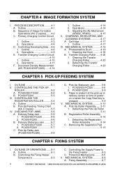
...Roller Assembly 5-14 1. Detaching the Registration Roller Assembly 5-14 C. Outline 6-1 B. Transfer Charging Control Circuit 4-10 1. MECHANICAL SYSTEM............4-18 A. PC400/FC200 5-6 B. PC400/FC200 5-9 E. Paper is present at the pick-up or delivery sensor at time of Image Formation Operations (A4, 2 copies) .......4-2 ... 4-10 2. Adjusting the AE Mechanism (VR602, VR603 4-15 II. Controlling the Supply Power to the Fixing Heater 6-3 D. Fixing Assembly 6-7 iv COPYRIGHT © 1998 CANON INC. CANON PC400/420/430,FC200/220 REV.0 JAN.1998 PRINTED IN JAPAN (IMPRIME AU JAPON) ...
...Roller Assembly 5-14 1. Detaching the Registration Roller Assembly 5-14 C. Outline 6-1 B. Transfer Charging Control Circuit 4-10 1. MECHANICAL SYSTEM............4-18 A. PC400/FC200 5-6 B. PC400/FC200 5-9 E. Paper is present at the pick-up or delivery sensor at time of Image Formation Operations (A4, 2 copies) .......4-2 ... 4-10 2. Adjusting the AE Mechanism (VR602, VR603 4-15 II. Controlling the Supply Power to the Fixing Heater 6-3 D. Fixing Assembly 6-7 iv COPYRIGHT © 1998 CANON INC. CANON PC400/420/430,FC200/220 REV.0 JAN.1998 PRINTED IN JAPAN (IMPRIME AU JAPON) ...

Service Manual
Page 7
... INSPECTION ADJUSTMENTS 10-5 10-3 A. Mechanical 10-5 A. Procedure 10-3 Image Width (position of glass).....10-5 II. CANON PC400/420/430,FC200/220 REV.0 JAN.1998 PRINTED IN JAPAN (IMPRIME AU JAPON) v Detaching the Fixing Assembly 6-7 3. Protection Mechanism for Power Supply Circuit 7-2 II.MECHANICAL SYSTEM 7-3 A. SELECTING THE SITE 8-1 II. PERIODICALLY REPLACED PARTS 9-1 II. Storing Unsealed...
... INSPECTION ADJUSTMENTS 10-5 10-3 A. Mechanical 10-5 A. Procedure 10-3 Image Width (position of glass).....10-5 II. CANON PC400/420/430,FC200/220 REV.0 JAN.1998 PRINTED IN JAPAN (IMPRIME AU JAPON) v Detaching the Fixing Assembly 6-7 3. Protection Mechanism for Power Supply Circuit 7-2 II.MECHANICAL SYSTEM 7-3 A. SELECTING THE SITE 8-1 II. PERIODICALLY REPLACED PARTS 9-1 II. Storing Unsealed...

Service Manual
Page 9
... © 1998 CANON INC. CANON PC400/420/430,FC200/220 REV.0 JAN.1998 PRINTED IN JAPAN (IMPRIME AU JAPON) vii B. GENERAL TIMING CHART .........A-1 B. Sensors and Solenoids.......10-34 B. Printed Circuit Board (PCB)10-37 E. Control Panel PCB.........10-39 VII. Lamp, Heater, Motor, and Others 10-36 D. DC Controller/DC Power Supply PCB 10...
... © 1998 CANON INC. CANON PC400/420/430,FC200/220 REV.0 JAN.1998 PRINTED IN JAPAN (IMPRIME AU JAPON) vii B. GENERAL TIMING CHART .........A-1 B. Sensors and Solenoids.......10-34 B. Printed Circuit Board (PCB)10-37 E. Control Panel PCB.........10-39 VII. Lamp, Heater, Motor, and Others 10-36 D. DC Controller/DC Power Supply PCB 10...

Service Manual
Page 15
Others COPYRIGHT © 1998 CANON INC. CANON PC400/420/430,FC200/220 REV.0 JAN.1998 PRINTED IN JAPAN (IMPRIME AU JAPON) 1-3 Specifications subject to 1 atm) 120V, 60Hz Power supply Serial numbers ZTG !!!!! (PC400:WHITE) ZTH !!!!! (PC400:GRAY) Serial numbers NVD !!!!! (FC220:WHITE) ZTJ !!!!! (PC420:WHITE) 230V, 50Hz RTL/PTQ !!!!! (FC200:WHITE) UTP/UTQ RTM/PTR !!!!! (FC220:WHITE...
Others COPYRIGHT © 1998 CANON INC. CANON PC400/420/430,FC200/220 REV.0 JAN.1998 PRINTED IN JAPAN (IMPRIME AU JAPON) 1-3 Specifications subject to 1 atm) 120V, 60Hz Power supply Serial numbers ZTG !!!!! (PC400:WHITE) ZTH !!!!! (PC400:GRAY) Serial numbers NVD !!!!! (FC220:WHITE) ZTJ !!!!! (PC420:WHITE) 230V, 50Hz RTL/PTQ !!!!! (FC200:WHITE) UTP/UTQ RTM/PTR !!!!! (FC220:WHITE...
Service Manual
Page 18
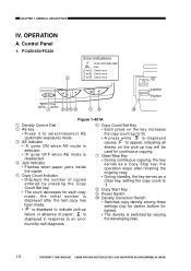
PC420/430/FC220 3 654 AE A Error indications : Check jam/Supply paper : Jam and : Check error and : Check error and : Check error C ON OFF 9 darker lighter lighter darker 1 ...displayed causes ' ' to appear, indicating all sheets on the key increases the copy count (up tray will be used for continuous copying. CANON PC400/420/430,FC200/220 REV.0 JAN.1998 PRINTED IN JAPAN (IMPRIME AU JAPON) OPERATION A. i Copy Start Key o Power Switch !0 Density ...to indicate pick-up failure or absence of copies entered by varying the developing bias. 1-6 COPYRIGHT © 1998 CANON INC.
PC420/430/FC220 3 654 AE A Error indications : Check jam/Supply paper : Jam and : Check error and : Check error and : Check error C ON OFF 9 darker lighter lighter darker 1 ...displayed causes ' ' to appear, indicating all sheets on the key increases the copy count (up tray will be used for continuous copying. CANON PC400/420/430,FC200/220 REV.0 JAN.1998 PRINTED IN JAPAN (IMPRIME AU JAPON) OPERATION A. i Copy Start Key o Power Switch !0 Density ...to indicate pick-up failure or absence of copies entered by varying the developing bias. 1-6 COPYRIGHT © 1998 CANON INC.
Service Manual
Page 34
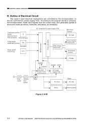
CHAPTER 2 BASIC OPERATION B. CANON PC400/420/430,FC200/220 REV.0 JAN.1998 PRINTED IN JAPAN (IMPRIME AU JAPON) Outline of Electrical Circuit The copier's main electrical mechanisms are controlled by the microprocessor on the DC controller/DC power supply PCB. According to the program stored in... Fixing heater temperature sensor TH1 Thermistor Power switch Control key Microprocessor Driver assembly DC controller/DC power supply PCB High-voltage transformer Scanning lamp Main motor Solenoid DC load Primary/Transfer charging roller Developing cylinder Q101 +DC5V Sub power...
CHAPTER 2 BASIC OPERATION B. CANON PC400/420/430,FC200/220 REV.0 JAN.1998 PRINTED IN JAPAN (IMPRIME AU JAPON) Outline of Electrical Circuit The copier's main electrical mechanisms are controlled by the microprocessor on the DC controller/DC power supply PCB. According to the program stored in... Fixing heater temperature sensor TH1 Thermistor Power switch Control key Microprocessor Driver assembly DC controller/DC power supply PCB High-voltage transformer Scanning lamp Main motor Solenoid DC load Primary/Transfer charging roller Developing cylinder Q101 +DC5V Sub power...

Service Manual
Page 37
...motor are generated while the motor is rotating. If the revolution of the motor is equipped with a motor rotation sensor (Q901) to these clock pulses. 2. CANON PC400/420/430,FC200/220 REV.0 JAN.1998 PRINTED IN JAPAN (IMPRIME AU JAPON) 2-5 controls the main motor speed (constant) The main motor (M1) is ...a DC motor and is slowed down. Operation The drive circuit on the DC controller/DC power supply PCB causes the main motor drive command (MMD) to go '0' in the main motor (M1), the speed controller circuit exerts control so that controls...
...motor are generated while the motor is rotating. If the revolution of the motor is equipped with a motor rotation sensor (Q901) to these clock pulses. 2. CANON PC400/420/430,FC200/220 REV.0 JAN.1998 PRINTED IN JAPAN (IMPRIME AU JAPON) 2-5 controls the main motor speed (constant) The main motor (M1) is ...a DC motor and is slowed down. Operation The drive circuit on the DC controller/DC power supply PCB causes the main motor drive command (MMD) to go '0' in the main motor (M1), the speed controller circuit exerts control so that controls...

Service Manual
Page 38
...J202-1 5V Turning density adjustment dial varies voltage. (turn to darken brings it closer to DC Controller 1. Figure 2-101E 2-6 COPYRIGHT © 1998 CANON INC. PC420/430/FC220 only) Power switch Density adjustment dial/lever SW604 +5V +5V VR601 J601 -14(-10) J601 -21(-16) J601-13...: The pin No. Inputs to the PC400/FC200. CHAPTER 2 BASIC OPERATION E. CANON PC400/420/430,FC200/220 REV.0 JAN.1998 PRINTED IN JAPAN (IMPRIME AU JAPON) in parentheses refers to DC Controller (1/2) DC controller/DC power supply PCB AC power supply Door switch SW1 Delivery door switch SW2 J104...
...J202-1 5V Turning density adjustment dial varies voltage. (turn to darken brings it closer to DC Controller 1. Figure 2-101E 2-6 COPYRIGHT © 1998 CANON INC. PC420/430/FC220 only) Power switch Density adjustment dial/lever SW604 +5V +5V VR601 J601 -14(-10) J601 -21(-16) J601-13...: The pin No. Inputs to the PC400/FC200. CHAPTER 2 BASIC OPERATION E. CANON PC400/420/430,FC200/220 REV.0 JAN.1998 PRINTED IN JAPAN (IMPRIME AU JAPON) in parentheses refers to DC Controller (1/2) DC controller/DC power supply PCB AC power supply Door switch SW1 Delivery door switch SW2 J104...

Service Manual
Page 39
... Q131 detects copy paper, oscillation signal (DGT2) is input. in parentheses refers to DC Controller (2/2) Delivery detection PCB DC controller/DC power supply PCB Delivery detection Q801 J801 J603 Fixing heater surface temperature detection J603 -1 TH1 -2 -3 -1 -2 -3 -5 -4 J601 -15(-10) ... detection Q901 -3 -1 Motor rotation detection PCB -1 MMCLK Clock pulses corresponding to -3 revolution of fixing heater increases, voltage lowers. CANON PC400/420/430,FC200/220 REV.0 JAN.1998 PRINTED IN JAPAN (IMPRIME AU JAPON) 2-7 CHAPTER 2 BASIC OPERATION 2. J621 PD601 J601...
... Q131 detects copy paper, oscillation signal (DGT2) is input. in parentheses refers to DC Controller (2/2) Delivery detection PCB DC controller/DC power supply PCB Delivery detection Q801 J801 J603 Fixing heater surface temperature detection J603 -1 TH1 -2 -3 -1 -2 -3 -5 -4 J601 -15(-10) ... detection Q901 -3 -1 Motor rotation detection PCB -1 MMCLK Clock pulses corresponding to -3 revolution of fixing heater increases, voltage lowers. CANON PC400/420/430,FC200/220 REV.0 JAN.1998 PRINTED IN JAPAN (IMPRIME AU JAPON) 2-7 CHAPTER 2 BASIC OPERATION 2. J621 PD601 J601...

Service Manual
Page 40
Outputs from DC Controller 1. Figure 2-101F 2-8 COPYRIGHT © 1998 CANON INC. Lamp PCB J903 -1 Main motor M1 -2 +24V J201 -5 -4 MMD When '0', main motor goes ON. CHAPTER 2 BASIC OPERATION F. Outputs from DC Controller (1/2) DC controller/DC power supply PCB Thermal fuse 2 FU2 H1 J101 See Chap.6. CANON PC400/420/430,FC200/220 REV.0 JAN.1998 PRINTED IN JAPAN (IMPRIME AU JAPON) J102 Fixing heater Scanning lamp LA1 to LA8 Thermal fuse 1 J906 FU1 J108 -1 -1 -2 -2 See Chap.3. High voltage output See Chap.4.
Outputs from DC Controller 1. Figure 2-101F 2-8 COPYRIGHT © 1998 CANON INC. Lamp PCB J903 -1 Main motor M1 -2 +24V J201 -5 -4 MMD When '0', main motor goes ON. CHAPTER 2 BASIC OPERATION F. Outputs from DC Controller (1/2) DC controller/DC power supply PCB Thermal fuse 2 FU2 H1 J101 See Chap.6. CANON PC400/420/430,FC200/220 REV.0 JAN.1998 PRINTED IN JAPAN (IMPRIME AU JAPON) J102 Fixing heater Scanning lamp LA1 to LA8 Thermal fuse 1 J906 FU1 J108 -1 -1 -2 -2 See Chap.3. High voltage output See Chap.4.

Service Manual
Page 41
...is switched between 24V and 15V to ensure stable operation) Figure 2-103F COPYRIGHT © 1998 CANON INC. PC400/FC200 Registration solenoid J901 -1 SL1 -2 Figure 2-102F DC controller/DC power supply PCB J201 +24V -7 -6 RGSD When '0', SL1 goes ON. CANON PC400/420/430,FC200/220 REV.0 JAN.1998 PRINTED IN JAPAN (IMPRIME AU JAPON) 2-9 Outputs... to SL2 is switched between 24V and 15V to ensure stable operation) b. PC420/430/FC220 Pick-up solenoid J901 -1 SL1 -2 DC controller/DC power supply PCB J201 +24V -7 -6 PUSD When '0', SL1 goes ON. CHAPTER 2 BASIC OPERATION 2.
...is switched between 24V and 15V to ensure stable operation) Figure 2-103F COPYRIGHT © 1998 CANON INC. PC400/FC200 Registration solenoid J901 -1 SL1 -2 Figure 2-102F DC controller/DC power supply PCB J201 +24V -7 -6 RGSD When '0', SL1 goes ON. CANON PC400/420/430,FC200/220 REV.0 JAN.1998 PRINTED IN JAPAN (IMPRIME AU JAPON) 2-9 Outputs... to SL2 is switched between 24V and 15V to ensure stable operation) b. PC420/430/FC220 Pick-up solenoid J901 -1 SL1 -2 DC controller/DC power supply PCB J201 +24V -7 -6 PUSD When '0', SL1 goes ON. CHAPTER 2 BASIC OPERATION 2.

Service Manual
Page 47
...for paper transport and the movement (forward, reverse, stop operations by the copyboard drive solenoid (SL2) and forward/ reverse switching mechanism. CANON PC400/420/430,FC200/220 REV.0 JAN.1998 PRINTED IN JAPAN (IMPRIME AU JAPON) 3-3 In response to the signal from Q902, the DC... glass J201 Copyboard drive gear -10 Copyboard drive solenoid drive command (CBSD) J201 -9 Copyboard drive solenoid SL2 DC controller/ DC power supply PCB Forward Forward/Reverse Reverse gear switching mechanism gear J201 -4 Main motor drive command (MMD) M1 Main motor Figure 3-102B Front View...
...for paper transport and the movement (forward, reverse, stop operations by the copyboard drive solenoid (SL2) and forward/ reverse switching mechanism. CANON PC400/420/430,FC200/220 REV.0 JAN.1998 PRINTED IN JAPAN (IMPRIME AU JAPON) 3-3 In response to the signal from Q902, the DC... glass J201 Copyboard drive gear -10 Copyboard drive solenoid drive command (CBSD) J201 -9 Copyboard drive solenoid SL2 DC controller/ DC power supply PCB Forward Forward/Reverse Reverse gear switching mechanism gear J201 -4 Main motor drive command (MMD) M1 Main motor Figure 3-102B Front View...

Service Manual
Page 51
... provided to prevent rush current occurring when the lamp turns on. FIgure 3-201A COPYRIGHT © 1998 CANON INC. In addition, a rush current protection circuit is checked by the lamp intensity detection signal (LID...8226; Turns the scanning lamp ON and OFF. • Controls the intensity of the scanning lamp has stabilized. CANON PC400/420/430,FC200/220 REV.0 JAN.1998 PRINTED IN JAPAN (IMPRIME AU JAPON) 3-7 An intensity sensor (PD601...13 Lamp intensity sensor signal (LID) Control panel PCB DC controller/DC power supply PCB The number within parentheses represents the PC400/FC200.
... provided to prevent rush current occurring when the lamp turns on. FIgure 3-201A COPYRIGHT © 1998 CANON INC. In addition, a rush current protection circuit is checked by the lamp intensity detection signal (LID...8226; Turns the scanning lamp ON and OFF. • Controls the intensity of the scanning lamp has stabilized. CANON PC400/420/430,FC200/220 REV.0 JAN.1998 PRINTED IN JAPAN (IMPRIME AU JAPON) 3-7 An intensity sensor (PD601...13 Lamp intensity sensor signal (LID) Control panel PCB DC controller/DC power supply PCB The number within parentheses represents the PC400/FC200.

Service Manual
Page 59
... the scanning lamp. • Controls the primary charging. • Controls the transfer charging. • Controls the developing bias. Figure 4-101A COPYRIGHT © 1998 CANON INC. CANON PC400/420/430,FC200/220 REV.0 JAN.1998 PRINTED IN JAPAN (IMPRIME AU JAPON) 4-1 Lamp intensity sensor Scanning lamp AE sensor Primary charging roller J621-4 -2 Control...(AE) Lamp ON command (LAPWM) Primary corona high voltage Static eliminator Transfer charging high voltage Developing bias J202-13 -19 DC controller/DC power supply PCB Note : The AE sensor is provided for the PC420/430/FC220 only.
... the scanning lamp. • Controls the primary charging. • Controls the transfer charging. • Controls the developing bias. Figure 4-101A COPYRIGHT © 1998 CANON INC. CANON PC400/420/430,FC200/220 REV.0 JAN.1998 PRINTED IN JAPAN (IMPRIME AU JAPON) 4-1 Lamp intensity sensor Scanning lamp AE sensor Primary charging roller J621-4 -2 Control...(AE) Lamp ON command (LAPWM) Primary corona high voltage Static eliminator Transfer charging high voltage Developing bias J202-13 -19 DC controller/DC power supply PCB Note : The AE sensor is provided for the PC420/430/FC220 only.

Service Manual
Page 63
CANON PC400/420/430,FC200/220 REV.0 JAN.1998 PRINTED IN JAPAN (IMPRIME AU JAPON) 4-5 Transformer (T106) DC bias control circuit DC current detection CHPTER 4 IMAGE FORMATION SYSTEM Amplifier Transformer (T103) J6 Primary charging roller Photosensitive drum Oscillation control circuit Oscillation circuit Current detection AC bias ON command (HVPAC) DC bias ON command (HVPDC) DC bias high output command (HVPHO) Microprocessor DC controller/DC power supply PCB Figure 4-101C COPYRIGHT © 1998 CANON INC.
CANON PC400/420/430,FC200/220 REV.0 JAN.1998 PRINTED IN JAPAN (IMPRIME AU JAPON) 4-5 Transformer (T106) DC bias control circuit DC current detection CHPTER 4 IMAGE FORMATION SYSTEM Amplifier Transformer (T103) J6 Primary charging roller Photosensitive drum Oscillation control circuit Oscillation circuit Current detection AC bias ON command (HVPAC) DC bias ON command (HVPDC) DC bias high output command (HVPHO) Microprocessor DC controller/DC power supply PCB Figure 4-101C COPYRIGHT © 1998 CANON INC.

Service Manual
Page 67
Transformer (T106) DC voltage detection DC bias control command (DCBPWM) AC bias timing pulse command (ACBTP) CHPTER 4 IMAGE FORMATION SYSTEM J7 5V Q146 Transformer (T104) Amplifier Photosensitive drum Developing cylinder AE signal AE J202 Density control dial VR601 Density correction switch SW606 Control panel PCB Microprocessor DC controller/DC power supply PCB Figure 4-104D COPYRIGHT © 1998 CANON INC. CANON PC400/420/430,FC200/220 REV.0 JAN.1998 PRINTED IN JAPAN (IMPRIME AU JAPON) 4-9
Transformer (T106) DC voltage detection DC bias control command (DCBPWM) AC bias timing pulse command (ACBTP) CHPTER 4 IMAGE FORMATION SYSTEM J7 5V Q146 Transformer (T104) Amplifier Photosensitive drum Developing cylinder AE signal AE J202 Density control dial VR601 Density correction switch SW606 Control panel PCB Microprocessor DC controller/DC power supply PCB Figure 4-104D COPYRIGHT © 1998 CANON INC. CANON PC400/420/430,FC200/220 REV.0 JAN.1998 PRINTED IN JAPAN (IMPRIME AU JAPON) 4-9

Service Manual
Page 71
CANON PC400/420/430,FC200/220 REV.0 JAN.1998 PRINTED IN JAPAN (IMPRIME AU JAPON) 4-13 CHPTER 4 IMAGE FORMATION SYSTEM Photosensitive drum Transfer charging roller Transformer (T106) ... bias ON command (TREV) Voltage sensor (analog signal) Transfer DC bias ON command (HVTDC) Transfer DC bias control command (DCTPWM) Microprocessor DC controller/DC power supply PCB Figure 4-101E COPYRIGHT © 1998 CANON INC.
CANON PC400/420/430,FC200/220 REV.0 JAN.1998 PRINTED IN JAPAN (IMPRIME AU JAPON) 4-13 CHPTER 4 IMAGE FORMATION SYSTEM Photosensitive drum Transfer charging roller Transformer (T106) ... bias ON command (TREV) Voltage sensor (analog signal) Transfer DC bias ON command (HVTDC) Transfer DC bias control command (DCTPWM) Microprocessor DC controller/DC power supply PCB Figure 4-101E COPYRIGHT © 1998 CANON INC.

Service Manual
Page 74
CHPTER 4 IMAGE FORMATION SYSTEM AE sensor PD602 Forward Scanning lamp Lens array J621 -2 J621 | -1 { Photosensitive drum Developing cylinder 4V (approx.) VR602 VR603 | { J601 J202 -4 -19 5V Amplifier circuit DC bias control circuit DCBPWM AE signal Microprocessor Control panel PCB DC controller/DC power supply PCB Figure 4-103F 4-16 COPYRIGHT © 1998 CANON INC. CANON PC400/420/430,FC200/220 REV.0 JAN.1998 PRINTED IN JAPAN (IMPRIME AU JAPON)
CHPTER 4 IMAGE FORMATION SYSTEM AE sensor PD602 Forward Scanning lamp Lens array J621 -2 J621 | -1 { Photosensitive drum Developing cylinder 4V (approx.) VR602 VR603 | { J601 J202 -4 -19 5V Amplifier circuit DC bias control circuit DCBPWM AE signal Microprocessor Control panel PCB DC controller/DC power supply PCB Figure 4-103F 4-16 COPYRIGHT © 1998 CANON INC. CANON PC400/420/430,FC200/220 REV.0 JAN.1998 PRINTED IN JAPAN (IMPRIME AU JAPON)

Service Manual
Page 81
...or move past the sensor, the copier identifies the condition as a jam and flashes 'Jam' on the photosensitive drum; DC controller/DC power supply PCB Delivery sensor signal Main motor drive command (MMD) Pick-up sensor signal Pick-up solenoid drive command (PUSD) Registration solenoid drive command (.... The delivery of copy paper is inserted, i.e., in response to the transfer, separation, and fixing assemblies before it reaches the copy tray. CANON PC400/420/430,FC200/220 REV.0 JAN.1998 PRINTED IN JAPAN (IMPRIME AU JAPON) 5-1 the paper is controlled by the delivery sensor (Q801); ...
...or move past the sensor, the copier identifies the condition as a jam and flashes 'Jam' on the photosensitive drum; DC controller/DC power supply PCB Delivery sensor signal Main motor drive command (MMD) Pick-up sensor signal Pick-up solenoid drive command (PUSD) Registration solenoid drive command (.... The delivery of copy paper is inserted, i.e., in response to the transfer, separation, and fixing assemblies before it reaches the copy tray. CANON PC400/420/430,FC200/220 REV.0 JAN.1998 PRINTED IN JAPAN (IMPRIME AU JAPON) 5-1 the paper is controlled by the delivery sensor (Q801); ...