
Service Manual
Page 34
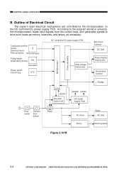
CANON PC400/420/430,FC200/220 REV.0 JAN.1998 PRINTED IN JAPAN (...Q Delivery sensor Pick-up sensor Photointerrupter Fixing heater temperature sensor TH1 Thermistor Power switch Control key Microprocessor Driver assembly DC controller/DC power supply PCB High-voltage transformer Scanning lamp Main motor Solenoid DC load Primary... DC power supply PCB Display Door switch Delivery door switch Relay AC driver Driver Heater AC load Scanning lamp Figure 2-101B 2-2 COPYRIGHT © 1998 CANON INC. Outline of Electrical Circuit The copier's main electrical mechanisms are controlled...
CANON PC400/420/430,FC200/220 REV.0 JAN.1998 PRINTED IN JAPAN (...Q Delivery sensor Pick-up sensor Photointerrupter Fixing heater temperature sensor TH1 Thermistor Power switch Control key Microprocessor Driver assembly DC controller/DC power supply PCB High-voltage transformer Scanning lamp Main motor Solenoid DC load Primary... DC power supply PCB Display Door switch Delivery door switch Relay AC driver Driver Heater AC load Scanning lamp Figure 2-101B 2-2 COPYRIGHT © 1998 CANON INC. Outline of Electrical Circuit The copier's main electrical mechanisms are controlled...

Service Manual
Page 51
...has stabilized. J621 -4 Scanning lamp (LA1-LA8) J108-1 +24VU - + Intensity sensor -3 (PD601) J108-2 (-1) Q143 Rush current protection circuit Lamp driver circuit Lamp ON signal (LAPWM) Microprocessor VR604 - + 5V Amplifier circuit J601 -10 (-5) J202 -13 Lamp intensity sensor signal (LID) Control panel PCB... when the lamp turns on. The intensity of the scanning lamp. CANON PC400/420/430,FC200/220 REV.0 JAN.1998 PRINTED IN JAPAN (IMPRIME AU JAPON) 3-7 FIgure 3-201A COPYRIGHT © 1998 CANON INC. Outline Figure 3-201A shows the circuit that the intensity has reached...
...has stabilized. J621 -4 Scanning lamp (LA1-LA8) J108-1 +24VU - + Intensity sensor -3 (PD601) J108-2 (-1) Q143 Rush current protection circuit Lamp driver circuit Lamp ON signal (LAPWM) Microprocessor VR604 - + 5V Amplifier circuit J601 -10 (-5) J202 -13 Lamp intensity sensor signal (LID) Control panel PCB... when the lamp turns on. The intensity of the scanning lamp. CANON PC400/420/430,FC200/220 REV.0 JAN.1998 PRINTED IN JAPAN (IMPRIME AU JAPON) 3-7 FIgure 3-201A COPYRIGHT © 1998 CANON INC. Outline Figure 3-201A shows the circuit that the intensity has reached...

Service Manual
Page 52
... adjust the intensity of the microprocessor (LAPWM com mand) grows low. CANON PC400/420/430,FC200/220 REV.0 JAN.1998 PRINTED IN JAPAN (IMPRIME AU JAPON) Output voltage of the lamp, causing the fluorescent lamp to the lamp driver circuit. (Q143 ON) Current flows into the filament of the amplifier ... of the LAPWM command corresponding to the lamp decreases. • If the microprocessor finds out that the scanning lamp has remained on for the PC400/FC200. Current flowing to the output of the microprocessor (LAPWM com mand) grows high. Duty ratio (H) of the output of the amplifi er...
... adjust the intensity of the microprocessor (LAPWM com mand) grows low. CANON PC400/420/430,FC200/220 REV.0 JAN.1998 PRINTED IN JAPAN (IMPRIME AU JAPON) Output voltage of the lamp, causing the fluorescent lamp to the lamp driver circuit. (Q143 ON) Current flows into the filament of the amplifier ... of the LAPWM command corresponding to the lamp decreases. • If the microprocessor finds out that the scanning lamp has remained on for the PC400/FC200. Current flowing to the output of the microprocessor (LAPWM com mand) grows high. Duty ratio (H) of the output of the amplifi er...

Service Manual
Page 113
CANON PC400/420/430,FC200/220 REV.0 JAN.1998 PRINTED IN JAPAN (IMPRIME AU JAPON) 7-1 Control panel Sensor Photointerrupter COPYRIGHT © 1998 CANON INC. Fixing heater Scanning lamp HVT assembly +24VR +24VU DC power supply +24VR assembly +5V T106 Main ... roller Developing cylinder Motor driver assembly Main motor (M1) DC load Solenoids, etc. CHAPTER 7 EXTERNALS/AUXILIARY MECHANISMS I. POWER SUPPLY A. Outline Power switch (SW604) Door switch Delivery door (SW1) switch (SW2) Microprocessor FU102 +DC5VL Sub power supply Relay RL101 AC driver FU101 Lamp drive +24VU...
CANON PC400/420/430,FC200/220 REV.0 JAN.1998 PRINTED IN JAPAN (IMPRIME AU JAPON) 7-1 Control panel Sensor Photointerrupter COPYRIGHT © 1998 CANON INC. Fixing heater Scanning lamp HVT assembly +24VR +24VU DC power supply +24VR assembly +5V T106 Main ... roller Developing cylinder Motor driver assembly Main motor (M1) DC load Solenoids, etc. CHAPTER 7 EXTERNALS/AUXILIARY MECHANISMS I. POWER SUPPLY A. Outline Power switch (SW604) Door switch Delivery door (SW1) switch (SW2) Microprocessor FU102 +DC5VL Sub power supply Relay RL101 AC driver FU101 Lamp drive +24VU...