
Service Manual
Page 2
...CONTAINED HEREIN SHOULD BE DIRECTED TO THE COPIER SERVICE DEPARTMENT OF THE SALES COMPANY. COPYRIGHT © 1998 CANON INC. CANON PC400/420/430,FC200/220 REV.0 JAN.1998 PRINTED IN JAPAN (IMPRIME AU JAPON) SPECIFICATIONS AND OTHER ...INFORMATION CONTAINED HEREIN MAY VARY SLIGHTLY FROM ACTUAL MACHINE VALUES OR THOSE FOUND IN ADVERTISING AND OTHER PRINTED MATTER. Prepared by OFFICE IMAGING PRODUCTS TECHNICAL SUPPORT DEPARTMENT 1 OFFICE IMAGING PRODUCTS TECHNICAL SUPPORT DIVISION CANON...
...CONTAINED HEREIN SHOULD BE DIRECTED TO THE COPIER SERVICE DEPARTMENT OF THE SALES COMPANY. COPYRIGHT © 1998 CANON INC. CANON PC400/420/430,FC200/220 REV.0 JAN.1998 PRINTED IN JAPAN (IMPRIME AU JAPON) SPECIFICATIONS AND OTHER ...INFORMATION CONTAINED HEREIN MAY VARY SLIGHTLY FROM ACTUAL MACHINE VALUES OR THOSE FOUND IN ADVERTISING AND OTHER PRINTED MATTER. Prepared by OFFICE IMAGING PRODUCTS TECHNICAL SUPPORT DEPARTMENT 1 OFFICE IMAGING PRODUCTS TECHNICAL SUPPORT DIVISION CANON...

Service Manual
Page 3
.../assembled and adjusted. CHAPTER 9, "Maintenance and Servicing," provides tables of maintenance/inspection, standards/adjustments, and problem identification (image fault/malfunction). It also shows how these units may be disassembled/assembled and adjusted. CHAPTER 10, "Troubleshooting," provides tables...in relation to their timing of operation. Appendix contains a general timing chart and general circuit diagrams. COPYRIGHT © 1998 CANON INC. CANON PC400/420/430,FC200/220 REV.0 JAN.1998 PRINTED IN JAPAN (IMPRIME AU JAPON) i CHAPTER 7, "Externals/Auxiliary Mechanisms," shows...
.../assembled and adjusted. CHAPTER 9, "Maintenance and Servicing," provides tables of maintenance/inspection, standards/adjustments, and problem identification (image fault/malfunction). It also shows how these units may be disassembled/assembled and adjusted. CHAPTER 10, "Troubleshooting," provides tables...in relation to their timing of operation. Appendix contains a general timing chart and general circuit diagrams. COPYRIGHT © 1998 CANON INC. CANON PC400/420/430,FC200/220 REV.0 JAN.1998 PRINTED IN JAPAN (IMPRIME AU JAPON) i CHAPTER 7, "Externals/Auxiliary Mechanisms," shows...
Service Manual
Page 5
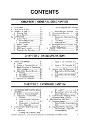
... ON and OFF 3-8 SYSTEM 3-1 2. Control Panel 1-6 1. Inputs to DC Controller (2/2 2-7 F. Controlling the Scanning Lamp....3-7 B. CANON PC400/420/430,FC200/220 REV.0 JAN.1998 PRINTED IN JAPAN (IMPRIME AU JAPON) iii CONTENTS CHAPTER 1 GENERAL DESCRIPTION I . Lens ...Array 1-15 3. Cross Section 1-5 IV. Replacing the Cartridge ........1-11 1. IMAGE FORMATION 1-17 A. Operation 2-5 3. Mechanism of Operations (A4, 2 copies 2-3 D. Outline 1-17 CHAPTER 2 BASIC OPERATION I . Outline...
... ON and OFF 3-8 SYSTEM 3-1 2. Control Panel 1-6 1. Inputs to DC Controller (2/2 2-7 F. Controlling the Scanning Lamp....3-7 B. CANON PC400/420/430,FC200/220 REV.0 JAN.1998 PRINTED IN JAPAN (IMPRIME AU JAPON) iii CONTENTS CHAPTER 1 GENERAL DESCRIPTION I . Lens ...Array 1-15 3. Cross Section 1-5 IV. Replacing the Cartridge ........1-11 1. IMAGE FORMATION 1-17 A. Operation 2-5 3. Mechanism of Operations (A4, 2 copies 2-3 D. Outline 1-17 CHAPTER 2 BASIC OPERATION I . Outline...
Service Manual
Page 6
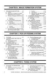
...Image Formation Operations (A4, 2 copies) .......4-2 C. Detaching the Pick-Up Roller 5-11 B. Registration Roller Assembly 5-14 1. Outline 6-1 B. CONTROLLING THE PICK-UP ROLLER 5-2 A. Outline 5-4 B. PC420/430/FC220 5-7 2. PC400/FC200 5-7 C. Pick-Up Delay Jam (PC420/430/FC220 5-8 D. OUTLINE OF OPERATIONS .......6-1 A. CANON PC400...4-6 2. Transfer Charging Control Circuit 4-10 1. Fixing Assembly 6-7 iv COPYRIGHT © 1998 CANON INC. CHAPTER 4 IMAGE FORMATION SYSTEM I . Controlling Developing Bias....4-6 1. Delivery Delay Jam 5-6 1. Sequence of poweron...
...Image Formation Operations (A4, 2 copies) .......4-2 C. Detaching the Pick-Up Roller 5-11 B. Registration Roller Assembly 5-14 1. Outline 6-1 B. CONTROLLING THE PICK-UP ROLLER 5-2 A. Outline 5-4 B. PC420/430/FC220 5-7 2. PC400/FC200 5-7 C. Pick-Up Delay Jam (PC420/430/FC220 5-8 D. OUTLINE OF OPERATIONS .......6-1 A. CANON PC400...4-6 2. Transfer Charging Control Circuit 4-10 1. Fixing Assembly 6-7 iv COPYRIGHT © 1998 CANON INC. CHAPTER 4 IMAGE FORMATION SYSTEM I . Controlling Developing Bias....4-6 1. Delivery Delay Jam 5-6 1. Sequence of poweron...

Service Manual
Page 7
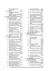
... the Bottom Cover 7-8 B. RELOCATING THE MACHINE ....8-5 CHAPTER 9 MAINTENANCE AND SERVICING I . NOTES ABOUT CARTRIDGE .....9-2 A. Handling the Cartridge.......9-3 CHAPTER 10 TROUBLESHOOTING I . Procedure 10-3 Image Width (position of glass).....10-5 II. STANDARDS AND 2. CANON PC400/420/430,FC200/220 REV.0 JAN.1998 PRINTED IN JAPAN (IMPRIME AU JAPON) v 1. Detaching the Pressure Roller 6-11 CHAPTER 7 EXTERNALS/AUXILIARY...
... the Bottom Cover 7-8 B. RELOCATING THE MACHINE ....8-5 CHAPTER 9 MAINTENANCE AND SERVICING I . NOTES ABOUT CARTRIDGE .....9-2 A. Handling the Cartridge.......9-3 CHAPTER 10 TROUBLESHOOTING I . Procedure 10-3 Image Width (position of glass).....10-5 II. STANDARDS AND 2. CANON PC400/420/430,FC200/220 REV.0 JAN.1998 PRINTED IN JAPAN (IMPRIME AU JAPON) v 1. Detaching the Pressure Roller 6-11 CHAPTER 7 EXTERNALS/AUXILIARY...
Service Manual
Page 8
...Copy Paper Jams 10-30 1. The copy has faulty leading 1. The copy has a blurred image. 4. The copy is foggy (overall). 10. Samples of jam) ..........10-29 13. Troubleshooting by Image Fault 1. (self diagnosis; 10-17 PC400/FC200 10-24 1. E0 10-24 areas only 10-17 3. E9 10-26 3. The... time of Image Faults ....10-16 IV. The copy has faulty leading 3. Checking the Copy Paper 22. AC power is foggy (cross feed 5. The copy has uneven density 8. The copyboard fails to operate 10-29 V. The copy has white lines (paper feed direction).....10-19 12. CANON PC400/420/430...
...Copy Paper Jams 10-30 1. The copy has faulty leading 1. The copy has a blurred image. 4. The copy is foggy (overall). 10. Samples of jam) ..........10-29 13. Troubleshooting by Image Fault 1. (self diagnosis; 10-17 PC400/FC200 10-24 1. E0 10-24 areas only 10-17 3. E9 10-26 3. The... time of Image Faults ....10-16 IV. The copy has faulty leading 3. Checking the Copy Paper 22. AC power is foggy (cross feed 5. The copy has uneven density 8. The copyboard fails to operate 10-29 V. The copy has white lines (paper feed direction).....10-19 12. CANON PC400/420/430...
Service Manual
Page 11
... E. Cleaning 1-14 H. Outline 1-17 COPYRIGHT © 1998 CANON INC. Cross Section 1-5 IV. When Not Using the Copier for a Long Time 1-16 V. CANON PC400/420/430,FC200/220 REV.0 JAN.1998 PRINTED IN JAPAN (...IMPRIME AU JAPON) 1 Control Panel 1-6 B. Replacing the Cartridge ........1-11 F. CHAPTER 1 GENERAL DESCRIPTION This chapter outlines the machine's specifications and how it may be operated. Jam Indicator 1-11 D. OPERATION 1-6 A. Changing the Density ...........1-14 G. I. External View 1-4 B. IMAGE...
... E. Cleaning 1-14 H. Outline 1-17 COPYRIGHT © 1998 CANON INC. Cross Section 1-5 IV. When Not Using the Copier for a Long Time 1-16 V. CANON PC400/420/430,FC200/220 REV.0 JAN.1998 PRINTED IN JAPAN (...IMPRIME AU JAPON) 1 Control Panel 1-6 B. Replacing the Cartridge ........1-11 F. CHAPTER 1 GENERAL DESCRIPTION This chapter outlines the machine's specifications and how it may be operated. Jam Indicator 1-11 D. OPERATION 1-6 A. Changing the Density ...........1-14 G. I. External View 1-4 B. IMAGE...
Service Manual
Page 14
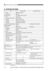
...about 50 sheets of 64 to 128 g/m2. Overlay copying • Paper of A4, 80 g/m2) Copy tray Non-image width 2 mm (leading edge) A4: 0 mm (left/right) LTR/LGL: 2 mm (left/right) 9 copies...LTR/A4; LGL* max.; A4/LTR, 80 g/m2) Auto power-off Available (5 min, approx.) *PC430 only. 1-2 COPYRIGHT © 1998 CANON INC. LGL* 1:1 (±1.2%) 0 sec (approx.; CHAPTER 1 GENERAL DESCRIPTION II. A4R/LTR-R 4 copies/min (A4R/LTR-R or or smaller...postcard min. 52 to 9 copies or F 4 copies/min (approx.; CANON PC400/420/430,FC200/220 REV.0 JAN.1998 PRINTED IN JAPAN (IMPRIME AU JAPON)
...about 50 sheets of 64 to 128 g/m2. Overlay copying • Paper of A4, 80 g/m2) Copy tray Non-image width 2 mm (leading edge) A4: 0 mm (left/right) LTR/LGL: 2 mm (left/right) 9 copies...LTR/A4; LGL* max.; A4/LTR, 80 g/m2) Auto power-off Available (5 min, approx.) *PC430 only. 1-2 COPYRIGHT © 1998 CANON INC. LGL* 1:1 (±1.2%) 0 sec (approx.; CHAPTER 1 GENERAL DESCRIPTION II. A4R/LTR-R 4 copies/min (A4R/LTR-R or or smaller...postcard min. 52 to 9 copies or F 4 copies/min (approx.; CANON PC400/420/430,FC200/220 REV.0 JAN.1998 PRINTED IN JAPAN (IMPRIME AU JAPON)
Service Manual
Page 29
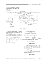
IMAGE FORMATION A. Development Delivery 6. CANON PC400/420/430,FC200/220 REV.0 JAN.1998 PRINTED IN JAPAN (IMPRIME AU JAPON) 1-17 Primary charging 2. Photoconductive layer Aluminum base Figure 1-503A COPYRIGHT © 1998 CANON INC. Drum cleaning 3. Outline Copyboard glass Scanning lamp Primary charging roller Lens array Developing blade Fixing film Cleaning blade Photosensitive drum Developing cylinder...
IMAGE FORMATION A. Development Delivery 6. CANON PC400/420/430,FC200/220 REV.0 JAN.1998 PRINTED IN JAPAN (IMPRIME AU JAPON) 1-17 Primary charging 2. Photoconductive layer Aluminum base Figure 1-503A COPYRIGHT © 1998 CANON INC. Drum cleaning 3. Outline Copyboard glass Scanning lamp Primary charging roller Lens array Developing blade Fixing film Cleaning blade Photosensitive drum Developing cylinder...
Service Manual
Page 33
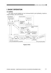
BASIC OPERATION A. CANON PC400/420/430,FC200/220 REV.0 JAN.1998 PRINTED IN JAPAN (IMPRIME AU JAPON) 2-1 Outline The copier can be divided into four functional blocks: pick-up /Feeding Block Figure 2-101A COPYRIGHT © 1998 CANON INC. CHAPTER 2 BASIC OPERATION ...I. Control Block Control panel Exposure Block Copyboard Control circuit Document exposure system Optical path Primary charging roller Image Formation Block Drum cleaning Photosensitive drum Developing assembly Feeding ...
BASIC OPERATION A. CANON PC400/420/430,FC200/220 REV.0 JAN.1998 PRINTED IN JAPAN (IMPRIME AU JAPON) 2-1 Outline The copier can be divided into four functional blocks: pick-up /Feeding Block Figure 2-101A COPYRIGHT © 1998 CANON INC. CHAPTER 2 BASIC OPERATION ...I. Control Block Control panel Exposure Block Copyboard Control circuit Document exposure system Optical path Primary charging roller Image Formation Block Drum cleaning Photosensitive drum Developing assembly Feeding ...
Service Manual
Page 36
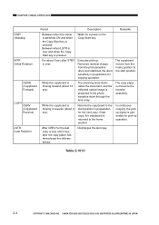
...illuminates the document, and the reflected optical image is moving in preparation for copying operation. CHAPTER 2 BASIC OPERATION Period Description Remarks STBY (Standby) Between when the copier is switched ON and when the Copy Start key is pressed. Discharges the last copy. CANON PC400/420/430,FC200/220 REV.0 JAN.1998... generated for the next copy; LSTR (Last Rotation) After CBRV for a press on the Copy Start key. Table 2-101C 2-4 COPYRIGHT © 1998 CANON INC. Waits for the last copy is moving forward (about 10 sec). While the copyboard is over .
...illuminates the document, and the reflected optical image is moving in preparation for copying operation. CHAPTER 2 BASIC OPERATION Period Description Remarks STBY (Standby) Between when the copier is switched ON and when the Copy Start key is pressed. Discharges the last copy. CANON PC400/420/430,FC200/220 REV.0 JAN.1998... generated for the next copy; LSTR (Last Rotation) After CBRV for a press on the Copy Start key. Table 2-101C 2-4 COPYRIGHT © 1998 CANON INC. Waits for the last copy is moving forward (about 10 sec). While the copyboard is over .

Service Manual
Page 57
.......4-6 E. CANON PC400/420/430,FC200/220 REV.0 JAN.1998 PRINTED IN JAPAN (IMPRIME AU JAPON) 1 PC420/430/FC220).......4-14 II. MECHANICAL SYSTEM............4-18 A. PROCESS DESCRIPTION..........4-1 A. Sequence of respective parts. CHAPTER 4 IMAGE FORMATION SYSTEM This chapter outlines the machine's image formation system... in relation to mechanisms and functions, relationship between electrical and mechanical systems,and the timing of operation of Image Formation Operations (A4, 2 copies) .......4-2 C. CHARGING, DEVELOPING, AND CLEANING SYSTEMS 4-17 A. Cartridge 4-17 III. ...
.......4-6 E. CANON PC400/420/430,FC200/220 REV.0 JAN.1998 PRINTED IN JAPAN (IMPRIME AU JAPON) 1 PC420/430/FC220).......4-14 II. MECHANICAL SYSTEM............4-18 A. PROCESS DESCRIPTION..........4-1 A. Sequence of respective parts. CHAPTER 4 IMAGE FORMATION SYSTEM This chapter outlines the machine's image formation system... in relation to mechanisms and functions, relationship between electrical and mechanical systems,and the timing of operation of Image Formation Operations (A4, 2 copies) .......4-2 C. CHARGING, DEVELOPING, AND CLEANING SYSTEMS 4-17 A. Cartridge 4-17 III. ...

Service Manual
Page 58
CANON PC400/420/430,FC200/220 REV.0 JAN.1998 PRINTED IN JAPAN (IMPRIME AU JAPON) CHPTER 4 IMAGE FORMATION SYSTEM Blank Page COPYRIGHT © 1998 CANON INC.
CANON PC400/420/430,FC200/220 REV.0 JAN.1998 PRINTED IN JAPAN (IMPRIME AU JAPON) CHPTER 4 IMAGE FORMATION SYSTEM Blank Page COPYRIGHT © 1998 CANON INC.

Service Manual
Page 59
PROCESS DESCRIPTION A. CHPTER 4 IMAGE FORMATION SYSTEM I. Figure 4-101A COPYRIGHT © 1998 CANON INC. CANON PC400/420/430,FC200/220 REV.0 JAN.1998 PRINTED IN JAPAN (IMPRIME AU JAPON) 4-1 Lamp intensity sensor Scanning lamp AE sensor Primary charging roller J621-4 ... bias J202-13 -19 DC controller/DC power supply PCB Note : The AE sensor is provided for the PC420/430/FC220 only. Outline The copier's image formation system has the following functions: • Controls the scanning lamp. • Controls the primary charging. • Controls the transfer charging. • ...
PROCESS DESCRIPTION A. CHPTER 4 IMAGE FORMATION SYSTEM I. Figure 4-101A COPYRIGHT © 1998 CANON INC. CANON PC400/420/430,FC200/220 REV.0 JAN.1998 PRINTED IN JAPAN (IMPRIME AU JAPON) 4-1 Lamp intensity sensor Scanning lamp AE sensor Primary charging roller J621-4 ... bias J202-13 -19 DC controller/DC power supply PCB Note : The AE sensor is provided for the PC420/430/FC220 only. Outline The copier's image formation system has the following functions: • Controls the scanning lamp. • Controls the primary charging. • Controls the transfer charging. • ...

Service Manual
Page 60
CANON PC400/420/430,FC200/220 REV.0 JAN.1998 PRINTED IN JAPAN (IMPRIME AU JAPON) Sequence of Image Formation Operations (A4, 2 copies) Power switch ON Copy paper inserted (PC400/FC200) Copy Start key ON Copy paper inserted (PC400/FC200) CBRV Sequence Copyboard 1 Main (M1) motor 2 Scanning lamp (LA1-LA8) STBY INTR CBRVSTOP CBFW COPY ...-625V Transfer charging : -400V : -120V to -560V (variable according to density control dial/ lever, AE) Figure 4-401B : Cleaning mode : Measurement mode : Transfer 4-2 COPYRIGHT © 1998 CANON INC. CHPTER 4 IMAGE FORMATION SYSTEM B.
CANON PC400/420/430,FC200/220 REV.0 JAN.1998 PRINTED IN JAPAN (IMPRIME AU JAPON) Sequence of Image Formation Operations (A4, 2 copies) Power switch ON Copy paper inserted (PC400/FC200) Copy Start key ON Copy paper inserted (PC400/FC200) CBRV Sequence Copyboard 1 Main (M1) motor 2 Scanning lamp (LA1-LA8) STBY INTR CBRVSTOP CBFW COPY ...-625V Transfer charging : -400V : -120V to -560V (variable according to density control dial/ lever, AE) Figure 4-401B : Cleaning mode : Measurement mode : Transfer 4-2 COPYRIGHT © 1998 CANON INC. CHPTER 4 IMAGE FORMATION SYSTEM B.

Service Manual
Page 61
... switched to -230V to maintain the surface potential of toner on the photosensitive drum. COPYRIGHT © 1998 CANON INC. CHPTER 4 IMAGE FORMATION SYSTEM C. Outline Figure 4-101C shows the circuit that controls the primary charging, and the circuit has ...the following functions: • Turns the DC bias ON and OFF. • Turns the AC bias ON and OFF. • Controls the DC bias voltage (constant). • Controls the AC bias current (constant). CANON PC400...
... switched to -230V to maintain the surface potential of toner on the photosensitive drum. COPYRIGHT © 1998 CANON INC. CHPTER 4 IMAGE FORMATION SYSTEM C. Outline Figure 4-101C shows the circuit that controls the primary charging, and the circuit has ...the following functions: • Turns the DC bias ON and OFF. • Turns the AC bias ON and OFF. • Controls the DC bias voltage (constant). • Controls the AC bias current (constant). CANON PC400...

Service Manual
Page 62
...c. Transformer T106 DC bias goes OFF. Transformer T103 goes OFF. HVPDC=0, HVPHO=0 (standby) DC bias control circuit goes OFF. CANON PC400/420/430,FC200/220 REV.0 JAN.1998 PRINTED IN JAPAN (IMPRIME AU JAPON) HVPAC=1 Oscillation control circuit goes ON. Transformer T103...ON. Transformer T106 generates DC bias. HVPAC=1 Oscillation control circuit goes ON. Operations a. CHPTER 4 IMAGE FORMATION SYSTEM 2. Primary charging (DC bias + AC bias) goes OFF. 4-4 COPYRIGHT © 1998 CANON INC. Primary charging (DC bias + AC bias) goes ON. HVPAC=0 Oscillation control circuit goes...
...c. Transformer T106 DC bias goes OFF. Transformer T103 goes OFF. HVPDC=0, HVPHO=0 (standby) DC bias control circuit goes OFF. CANON PC400/420/430,FC200/220 REV.0 JAN.1998 PRINTED IN JAPAN (IMPRIME AU JAPON) HVPAC=1 Oscillation control circuit goes ON. Transformer T103...ON. Transformer T106 generates DC bias. HVPAC=1 Oscillation control circuit goes ON. Operations a. CHPTER 4 IMAGE FORMATION SYSTEM 2. Primary charging (DC bias + AC bias) goes OFF. 4-4 COPYRIGHT © 1998 CANON INC. Primary charging (DC bias + AC bias) goes ON. HVPAC=0 Oscillation control circuit goes...

Service Manual
Page 63
Transformer (T106) DC bias control circuit DC current detection CHPTER 4 IMAGE FORMATION SYSTEM Amplifier Transformer (T103) J6 Primary charging roller Photosensitive drum Oscillation control circuit Oscillation circuit Current detection AC bias ON command (HVPAC) DC bias ON command (HVPDC) DC bias high output command (HVPHO) Microprocessor DC controller/DC power supply PCB Figure 4-101C COPYRIGHT © 1998 CANON INC. CANON PC400/420/430,FC200/220 REV.0 JAN.1998 PRINTED IN JAPAN (IMPRIME AU JAPON) 4-5
Transformer (T106) DC bias control circuit DC current detection CHPTER 4 IMAGE FORMATION SYSTEM Amplifier Transformer (T103) J6 Primary charging roller Photosensitive drum Oscillation control circuit Oscillation circuit Current detection AC bias ON command (HVPAC) DC bias ON command (HVPDC) DC bias high output command (HVPHO) Microprocessor DC controller/DC power supply PCB Figure 4-101C COPYRIGHT © 1998 CANON INC. CANON PC400/420/430,FC200/220 REV.0 JAN.1998 PRINTED IN JAPAN (IMPRIME AU JAPON) 4-5
Service Manual
Page 64
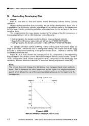
... (lighter) -100 -200 -300 -400 -500 Developing bias DC component (V) Figure 4-101D Manual Density Control (PC400/FC200) 4-6 COPYRIGHT © 1998 CANON INC. Outline Both AC bias and DC bias are applied to the developing cylinder regardless of the settings made by ... the same developing bias as for the black toner for man ual density control as well. PC420/430/FC220). CANON PC400/420/430,FC200/220 REV.0 JAN.1998 PRINTED IN JAPAN (IMPRIME AU JAPON) PC420/430/FC220). • ..., shows changes in the sensitivity of the photo sensitive drum. CHPTER 4 IMAGE FORMATION SYSTEM D.
... (lighter) -100 -200 -300 -400 -500 Developing bias DC component (V) Figure 4-101D Manual Density Control (PC400/FC200) 4-6 COPYRIGHT © 1998 CANON INC. Outline Both AC bias and DC bias are applied to the developing cylinder regardless of the settings made by ... the same developing bias as for the black toner for man ual density control as well. PC420/430/FC220). CANON PC400/420/430,FC200/220 REV.0 JAN.1998 PRINTED IN JAPAN (IMPRIME AU JAPON) PC420/430/FC220). • ..., shows changes in the sensitivity of the photo sensitive drum. CHPTER 4 IMAGE FORMATION SYSTEM D.
Service Manual
Page 65
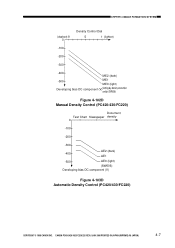
CHPTER 4 IMAGE FORMATION SYSTEM (darker) 9 0 Density Control Dial 5 1 (lighter) -100 -200 -300 -400 ME2 (dark) -500 ME1 ME0 (light) Developing bias DC component (V)Setting by density correction ... -200 -300 -400 AE2 (dark) AE1 -500 AE0 (light) (SW606) Developing bias DC component (V) Figure 4-103D Automatic Density Control (PC420/430/FC220) COPYRIGHT © 1998 CANON INC. CANON PC400/420/430,FC200/220 REV.0 JAN.1998 PRINTED IN JAPAN (IMPRIME AU JAPON) 4-7
CHPTER 4 IMAGE FORMATION SYSTEM (darker) 9 0 Density Control Dial 5 1 (lighter) -100 -200 -300 -400 ME2 (dark) -500 ME1 ME0 (light) Developing bias DC component (V)Setting by density correction ... -200 -300 -400 AE2 (dark) AE1 -500 AE0 (light) (SW606) Developing bias DC component (V) Figure 4-103D Automatic Density Control (PC420/430/FC220) COPYRIGHT © 1998 CANON INC. CANON PC400/420/430,FC200/220 REV.0 JAN.1998 PRINTED IN JAPAN (IMPRIME AU JAPON) 4-7


