
Service Manual
Page 5
SPECIFICATIONS 2.1 General Specification 2.2 Communication Specification 2.3 Color Communication Specification 2.4 Scanner Specification 2.5 Printer Specification 2.6 Copy Specification 2.7 Function 3. MAINTENANCE LIST 1.1 Consumables 1.2 Cleaning 1.3 Periodic Inspection 1.4 Periodic Replacement Parts 1.5 Adjustment Items 1.6 General Tools 1.7 Special Tools 2. HOW TO CLEAN PARTS 2.1 Main Unit ...
SPECIFICATIONS 2.1 General Specification 2.2 Communication Specification 2.3 Color Communication Specification 2.4 Scanner Specification 2.5 Printer Specification 2.6 Copy Specification 2.7 Function 3. MAINTENANCE LIST 1.1 Consumables 1.2 Cleaning 1.3 Periodic Inspection 1.4 Periodic Replacement Parts 1.5 Adjustment Items 1.6 General Tools 1.7 Special Tools 2. HOW TO CLEAN PARTS 2.1 Main Unit ...
Service Manual
Page 6
... 3 -40 3 -40 3 -41 3 -41 3 -42 3 -43 3 -43 3 -43 3 -43 3 -44 3 -45 3 -52 3 -53 2.3 Document Feed/Eject Roller 2.4 Separation Guide 2.5 Scanning Glass (Contact Sensor) 2.6 White Sheet 2.7 Printer Platen 3. COMMUNICATION SYSTEM OPERATIONS 5.1 FAX/TEL Switching 5.1.1 Settings 5.1.2 Parameters 5.2 Answering Machine Connection 5.2.1 Settings 5.2.2 Parameters 5.3 Manual/Auto Reception Switching 5.3.1 Settings 5.3.2 Parameters 5.4 Operations Where Other Machine Does...
... 3 -40 3 -40 3 -41 3 -41 3 -42 3 -43 3 -43 3 -43 3 -43 3 -44 3 -45 3 -52 3 -53 2.3 Document Feed/Eject Roller 2.4 Separation Guide 2.5 Scanning Glass (Contact Sensor) 2.6 White Sheet 2.7 Printer Platen 3. COMMUNICATION SYSTEM OPERATIONS 5.1 FAX/TEL Switching 5.1.1 Settings 5.1.2 Parameters 5.2 Answering Machine Connection 5.2.1 Settings 5.2.2 Parameters 5.3 Manual/Auto Reception Switching 5.3.1 Settings 5.3.2 Parameters 5.4 Operations Where Other Machine Does...

Service Manual
Page 7
... overview 7.2.2 Test mode flowchart 7.2.3 D-RAM tests 7.2.4 CS tests 7.2.5 PRINT test 7.2.6 Modem and NCU tests 7.2.7 Faculty tests 7.2.8 Printer test 8. WIRING DIAGRAM 9.1 Wiring Diagram 10. SERVICE REPORT 8.1 Report Output Function 8.1.1 User report output functions 8.1.2 Service report output ...functions 9. USER DATA FLOW 1.1 User Data Flow (by Operation Panel) 1.2 User Data Flow (by MultiPASS Suite) INDEX VI 3 -57 3 -57 3 -57 3 -58 3 -58 3 -59 3 -61 3 -61 3 -62 3 -64 3 -67 3 -72 3 -73...
... overview 7.2.2 Test mode flowchart 7.2.3 D-RAM tests 7.2.4 CS tests 7.2.5 PRINT test 7.2.6 Modem and NCU tests 7.2.7 Faculty tests 7.2.8 Printer test 8. WIRING DIAGRAM 9.1 Wiring Diagram 10. SERVICE REPORT 8.1 Report Output Function 8.1.1 User report output functions 8.1.2 Service report output ...functions 9. USER DATA FLOW 1.1 User Data Flow (by Operation Panel) 1.2 User Data Flow (by MultiPASS Suite) INDEX VI 3 -57 3 -57 3 -57 3 -58 3 -58 3 -59 3 -61 3 -61 3 -62 3 -64 3 -67 3 -72 3 -73...
Service Manual
Page 8
... a external-phone is detected by UHQ(Ultra High quality), Canon's vivid image processing technology. PC Fax By connecting this fax is a G3 transreceiving facsimile based on the ITU-T recommendations. Picture Quality Color Printer High quality printing can be used as -is no worry... be registered, and group dial and broadcasting transmission can be done. Reading in telephone networks. *: This mark indicates a new function. MultiPASS C755 Chapter 1: General Description 1. FEATURES 1.1 Overview This product is able to 99 pages can be copied at a resolution of 300dpi, and...
... a external-phone is detected by UHQ(Ultra High quality), Canon's vivid image processing technology. PC Fax By connecting this fax is a G3 transreceiving facsimile based on the ITU-T recommendations. Picture Quality Color Printer High quality printing can be used as -is no worry... be registered, and group dial and broadcasting transmission can be done. Reading in telephone networks. *: This mark indicates a new function. MultiPASS C755 Chapter 1: General Description 1. FEATURES 1.1 Overview This product is able to 99 pages can be copied at a resolution of 300dpi, and...

Service Manual
Page 13
MultiPASS C755 Chapter 1: General Description 2.5 Printer Specification Printing method Bubble-jet ink on-...Color Approx. 4.6 page/minute Printing resolution 360 dpi × 360 dpi (Normal print), 1440 dpi × 720 dpi (Printer mode) 180 dpi × 180 dpi (Economy print*) *Printing in case of paper tray 1tray : Legal/Letter/A4 (Universal... ) Paper capacity Max. 0.40" (10 mm) thickness plain paper (Approx. 100 sheets) Recommended paper Canon Copier LTR/LGL Premium Paper Weight 75 g/m2 Paper size Letter, Legal Manufactured by BOISE CASCADE PLOVER BOND Weight Paper...
MultiPASS C755 Chapter 1: General Description 2.5 Printer Specification Printing method Bubble-jet ink on-...Color Approx. 4.6 page/minute Printing resolution 360 dpi × 360 dpi (Normal print), 1440 dpi × 720 dpi (Printer mode) 180 dpi × 180 dpi (Economy print*) *Printing in case of paper tray 1tray : Legal/Letter/A4 (Universal... ) Paper capacity Max. 0.40" (10 mm) thickness plain paper (Approx. 100 sheets) Recommended paper Canon Copier LTR/LGL Premium Paper Weight 75 g/m2 Paper size Letter, Legal Manufactured by BOISE CASCADE PLOVER BOND Weight Paper...

Service Manual
Page 14
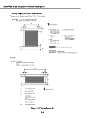
...) 0.12"±0.06" (3.0±1.5 mm) 0.20"±0.12" (5.0±3.0 mm) NOTE • The header and footer are inches with mm shown in user data "PRINTER SETTINGS", "PAPER SIZE". 1-7 MultiPASS C755 Chapter 1: General Description Printing range (Black & White FAX) Paper dimensions (W × L) Letter 8.50" × 10.98" (216 mm × 279 mm) Legal 8.50...
...) 0.12"±0.06" (3.0±1.5 mm) 0.20"±0.12" (5.0±3.0 mm) NOTE • The header and footer are inches with mm shown in user data "PRINTER SETTINGS", "PAPER SIZE". 1-7 MultiPASS C755 Chapter 1: General Description Printing range (Black & White FAX) Paper dimensions (W × L) Letter 8.50" × 10.98" (216 mm × 279 mm) Legal 8.50...
Service Manual
Page 15
....0 mm f = 0.91 inch/23.0 mm (BC-30) 1.02 inch/26.0 mm (BC-33/34 Photo) b f : Recommended printing area : Printable area (contains recomended printing area) Envelopes W ! MultiPASS C755 Chapter 1: General Description Printing range (Color FAX & Printer mode) Plain paper and Special media (Color FAX...
....0 mm f = 0.91 inch/23.0 mm (BC-30) 1.02 inch/26.0 mm (BC-33/34 Photo) b f : Recommended printing area : Printable area (contains recomended printing area) Envelopes W ! MultiPASS C755 Chapter 1: General Description Printing range (Color FAX & Printer mode) Plain paper and Special media (Color FAX...
Service Manual
Page 19
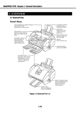
DOCUMENT GUIDES Keep the document in the multipurpose tray. When closed, serves as they exit the MultiPASS. MULTI-PURPOSE TRAY Holds plain paper and other print media. PAPER THICKNESS LEVER Adjusts the gap between the print head and the ... REST Supports print media stacked in position when being scanned. MultiPASS C755 Chapter 1: General Description 3. OUTPUT TRAY Holds printed pages as a cover for the operation panel. OVERVIEW 3.1 External View Front View ADF (AUTOMATIC DOCUMENT FEEDER) and PRINTER COVER Holds documents to the width of the print media. PAPER GUIDE Keeps ...
DOCUMENT GUIDES Keep the document in the multipurpose tray. When closed, serves as they exit the MultiPASS. MULTI-PURPOSE TRAY Holds plain paper and other print media. PAPER THICKNESS LEVER Adjusts the gap between the print head and the ... REST Supports print media stacked in position when being scanned. MultiPASS C755 Chapter 1: General Description 3. OUTPUT TRAY Holds printed pages as a cover for the operation panel. OVERVIEW 3.1 External View Front View ADF (AUTOMATIC DOCUMENT FEEDER) and PRINTER COVER Holds documents to the width of the print media. PAPER GUIDE Keeps ...

Service Manual
Page 26
... with letters enclosed. Copier paper has a preferred side for use this paper with Bubble Jet printers and produces bright and vivid color images. s Banner Paper Canon Banner Paper is a high gloss, thick paper that produces the look and feel of other ...Canon Banner Paper is designed to print photorealistic images. You can use paper without curls, folds, staples, or damaged edges. Commercial No. 10 envelopes and European DL envelopes. For best results, use with the Photo BJ cartridge to produce nearphotographic quality print output with sharp and vivid graphics. MultiPASS C755...
... with letters enclosed. Copier paper has a preferred side for use this paper with Bubble Jet printers and produces bright and vivid color images. s Banner Paper Canon Banner Paper is a high gloss, thick paper that produces the look and feel of other ...Canon Banner Paper is designed to print photorealistic images. You can use paper without curls, folds, staples, or damaged edges. Commercial No. 10 envelopes and European DL envelopes. For best results, use with the Photo BJ cartridge to produce nearphotographic quality print output with sharp and vivid graphics. MultiPASS C755...

Service Manual
Page 27
MultiPASS C755 Chapter 1: General Description s Bubble Jet Paper LC-301 Canon Bubble Jet Paper LC-301 has been developed for high quality printing with minimal or no smearing or running when in the MultiPASS as they do not absorb ink and may cause ink to run. This specially coated paper produces ...is printed on other paper. This film provides the best color print quality for Bubble Jet printers. Do not use normal transparencies in contact with coated paper. s Back Print Film BF-102 Canon Back Print Film BF-102 has been specially developed for the Color BJ cartridge. Figure 1-13...
MultiPASS C755 Chapter 1: General Description s Bubble Jet Paper LC-301 Canon Bubble Jet Paper LC-301 has been developed for high quality printing with minimal or no smearing or running when in the MultiPASS as they do not absorb ink and may cause ink to run. This specially coated paper produces ...is printed on other paper. This film provides the best color print quality for Bubble Jet printers. Do not use normal transparencies in contact with coated paper. s Back Print Film BF-102 Canon Back Print Film BF-102 has been specially developed for the Color BJ cartridge. Figure 1-13...

Service Manual
Page 31
DISASSEMBLY/ASSEMBLY 2.1 Parts Layout The parts layout of this machine consists of the scanning assembly, printing assembly and printer. Separation roller Document feed motor Pick up roller Lifting plate Document eject roller Document feed roller Paper feed motor Paper eject roller Document feed section Carriage motor Carriage belt Paper feed roller Document path Paper path Printer section Paper feed section Figure 2-2 Mechanical Layout 2-4 MultiPASS C755 Chapter 2: Assembly and Disassembly 2.
DISASSEMBLY/ASSEMBLY 2.1 Parts Layout The parts layout of this machine consists of the scanning assembly, printing assembly and printer. Separation roller Document feed motor Pick up roller Lifting plate Document eject roller Document feed roller Paper feed motor Paper eject roller Document feed section Carriage motor Carriage belt Paper feed roller Document path Paper path Printer section Paper feed section Figure 2-2 Mechanical Layout 2-4 MultiPASS C755 Chapter 2: Assembly and Disassembly 2.

Service Manual
Page 32
... chamber (Reflection-type sensor). Home position sensor: Detects the carriage position and purge unit status. MultiPASS C755 Chapter 2: Assembly and Disassembly The electrical parts are laid out as follows. • SCNT board system control • PCNT board printer control • NCU board interface with telephone line • Power supply unit supplies power to...
... chamber (Reflection-type sensor). Home position sensor: Detects the carriage position and purge unit status. MultiPASS C755 Chapter 2: Assembly and Disassembly The electrical parts are laid out as follows. • SCNT board system control • PCNT board printer control • NCU board interface with telephone line • Power supply unit supplies power to...

Service Manual
Page 33
Numbers in parenthese indicate the disassembly number. Main unit Upper cover / Printer cover (1) Replace the ROM (22) PCNT board (13) Scanner & Operation panel (2) Operation panel (7) Separation guide (8) Separation roller (11) White sheet unit (9) Document feed motor...) Carriage unit (17) ASF unit (14) Ink sensor (20) Carriage motor (18) Pick-up roller (15) Spur unit (21) Figure 2-4 Disassembly Work-Flow 2-6 MultiPASS C755 Chapter 2: Assembly and Disassembly 2.2 Disassembly Work-Flow The work-flow for the disassembly of the main units is as follows. In order to replace parts...
Numbers in parenthese indicate the disassembly number. Main unit Upper cover / Printer cover (1) Replace the ROM (22) PCNT board (13) Scanner & Operation panel (2) Operation panel (7) Separation guide (8) Separation roller (11) White sheet unit (9) Document feed motor...) Carriage unit (17) ASF unit (14) Ink sensor (20) Carriage motor (18) Pick-up roller (15) Spur unit (21) Figure 2-4 Disassembly Work-Flow 2-6 MultiPASS C755 Chapter 2: Assembly and Disassembly 2.2 Disassembly Work-Flow The work-flow for the disassembly of the main units is as follows. In order to replace parts...

Service Manual
Page 34
When attaching the cover, fit the tabs in the diagram and prise loose the tabs. The front part of the cover is fastened with tabs, so it needs to be pulled forward and then lifted up. a d c b Figure 2-5 Disassembly 1 NOTE To remove the upper cover, insert the tool into the two holes shown in first. 2-7 Upper covers/printer covers (1) Remove the three screws (a). (2) Remove the two tabs (b), then remove the upper cover (c), and the printer cover (d). MultiPASS C755 Chapter 2: Assembly and Disassembly 2.3 Disassembly Procedure Disassembly 1.
When attaching the cover, fit the tabs in the diagram and prise loose the tabs. The front part of the cover is fastened with tabs, so it needs to be pulled forward and then lifted up. a d c b Figure 2-5 Disassembly 1 NOTE To remove the upper cover, insert the tool into the two holes shown in first. 2-7 Upper covers/printer covers (1) Remove the three screws (a). (2) Remove the two tabs (b), then remove the upper cover (c), and the printer cover (d). MultiPASS C755 Chapter 2: Assembly and Disassembly 2.3 Disassembly Procedure Disassembly 1.

Service Manual
Page 38
Then perform Disassembly 3 (2). (2) Remove the two screws (a). (3) Use a screwdriver or similar to prise loose the two tabs (e). (4) Take hold of the handles shown in the diagram, and take out the printer (c). Disassembly 5. a c b b d a e Figure 2-8 Disassembly 4 and Disassembly 5 2-11 and then remove the printer assembly. (2) Remove the two screws (b). (2) Remove the power supply unit (d). from (2) till (4). Print ass'y (1) Perform Disassembly 1., and Disassembly 2. MultiPASS C755 Chapter 2: Assembly and Disassembly Disassembly 4. Power supply unit (1) Perform Disassembly 4.
Then perform Disassembly 3 (2). (2) Remove the two screws (a). (3) Use a screwdriver or similar to prise loose the two tabs (e). (4) Take hold of the handles shown in the diagram, and take out the printer (c). Disassembly 5. a c b b d a e Figure 2-8 Disassembly 4 and Disassembly 5 2-11 and then remove the printer assembly. (2) Remove the two screws (b). (2) Remove the power supply unit (d). from (2) till (4). Print ass'y (1) Perform Disassembly 1., and Disassembly 2. MultiPASS C755 Chapter 2: Assembly and Disassembly Disassembly 4. Power supply unit (1) Perform Disassembly 4.

Service Manual
Page 39
... volume of the other. Waste ink absorber (1) Perform Disassembly 4. MultiPASS C755 Chapter 2: Assembly and Disassembly Disassembly 6. Once the volume is counted and these data stored in order to reset the waste ink volume counter. 2-12 and then remove the printer assembly. (2) Remove the two waste ink absorber (a, b), one of... which is on top of ink absorbed is judged to have reached 100%, the message "CHECK PRINTER" (error code ##342) will be displayed, and printing will stop, in the EEPROM on how to ensure that the volume of waste ink ...
... volume of the other. Waste ink absorber (1) Perform Disassembly 4. MultiPASS C755 Chapter 2: Assembly and Disassembly Disassembly 6. Once the volume is counted and these data stored in order to reset the waste ink volume counter. 2-12 and then remove the printer assembly. (2) Remove the two waste ink absorber (a, b), one of... which is on top of ink absorbed is judged to have reached 100%, the message "CHECK PRINTER" (error code ##342) will be displayed, and printing will stop, in the EEPROM on how to ensure that the volume of waste ink ...

Service Manual
Page 46
...lever and sliding the carriage to release the carriage lock manually. MultiPASS C755 Chapter 2: Assembly and Disassembly NOTE Carriage lock release With a cartridge and carriage mounted, when the printer is powered off, it is released. When the printer is able to be released by removing the cartridge and pushing down... on , the carriage lock is usually locked in the carriage capping position. Figure 2-18 Carriage Lock Release 2-19 However, if the printer is not working normally, you may...
...lever and sliding the carriage to release the carriage lock manually. MultiPASS C755 Chapter 2: Assembly and Disassembly NOTE Carriage lock release With a cartridge and carriage mounted, when the printer is powered off, it is released. When the printer is able to be released by removing the cartridge and pushing down... on , the carriage lock is usually locked in the carriage capping position. Figure 2-18 Carriage Lock Release 2-19 However, if the printer is not working normally, you may...

Service Manual
Page 47
and remove the printer. (2) Loosen the two screws (a), and remove the carriage belt. (3) Remove the two pins (b). (4) Remove the spring (c). (5) Remove the paper selector lever (d). (6) Remove the carriage shaft (e). (7) Remove the two flat cables connecting the PCNT board to the carriage. (8) Remove the cable guide (f). (9) Remove the carriage unit (g). e b a f g c b d Figure 2-19 Disassembly 17 2-20 Carriage unit (1) Carry out Disassembly 4. MultiPASS C755 Chapter 2: Assembly and Disassembly Disassembly 17.
and remove the printer. (2) Loosen the two screws (a), and remove the carriage belt. (3) Remove the two pins (b). (4) Remove the spring (c). (5) Remove the paper selector lever (d). (6) Remove the carriage shaft (e). (7) Remove the two flat cables connecting the PCNT board to the carriage. (8) Remove the cable guide (f). (9) Remove the carriage unit (g). e b a f g c b d Figure 2-19 Disassembly 17 2-20 Carriage unit (1) Carry out Disassembly 4. MultiPASS C755 Chapter 2: Assembly and Disassembly Disassembly 17.

Service Manual
Page 48
Carriage motor (1) Carry out Disassembly 4. Disassembly 19. and remove the printer assembly. (2) Remove the two screws (c). (3) Remove the carriage motor (d). Paper feed motor (1) Perform disassembly up to Disassembly 17 (2) and take off the carriage belt. (2) Remove the two screws (a). (3) Remove the paper feed motor (b). MultiPASS C755 Chapter 2: Assembly and Disassembly Disassembly 18. c d a b Figure 2-20 Disassembly 18 and Disassembly 19 2-21
Carriage motor (1) Carry out Disassembly 4. Disassembly 19. and remove the printer assembly. (2) Remove the two screws (c). (3) Remove the carriage motor (d). Paper feed motor (1) Perform disassembly up to Disassembly 17 (2) and take off the carriage belt. (2) Remove the two screws (a). (3) Remove the paper feed motor (b). MultiPASS C755 Chapter 2: Assembly and Disassembly Disassembly 18. c d a b Figure 2-20 Disassembly 18 and Disassembly 19 2-21

Service Manual
Page 49
MultiPASS C755 Chapter 2: Assembly and Disassembly Disassembly 20. Spur unit (1) Carry out Disassembly 20. (2) Disengage the tab (c). (3) Remove the Spur unit (d). Disassembly 21. a b d c Figure 2-21 Disassembly 20 and Disassembly 21 2-22 Ink sensor (1) Carry out Disassembly 4., and remove the printer assembly. (2) Take off the sensor cover (a). (3) Disengage the ink sensor (b), from the connector cables.
MultiPASS C755 Chapter 2: Assembly and Disassembly Disassembly 20. Spur unit (1) Carry out Disassembly 20. (2) Disengage the tab (c). (3) Remove the Spur unit (d). Disassembly 21. a b d c Figure 2-21 Disassembly 20 and Disassembly 21 2-22 Ink sensor (1) Carry out Disassembly 4., and remove the printer assembly. (2) Take off the sensor cover (a). (3) Disengage the ink sensor (b), from the connector cables.


