
Service Manual
Page 4
... information bulletins. CANOSCAN N650U/N656U/N1220U REV.0 JUNE 2000 PRINTED IN JAPAN (IMPRIME AU JAPON) A thorough understanding of the N650U/N656U/N1220U, based on the service manual and service information bulletins, is vital to change as the product is improved. COPYRIGHT © 2000 CANON INC. Chapter 1: General Descriptions Features, specifications, exterior features, installation, customer's daily...
... information bulletins. CANOSCAN N650U/N656U/N1220U REV.0 JUNE 2000 PRINTED IN JAPAN (IMPRIME AU JAPON) A thorough understanding of the N650U/N656U/N1220U, based on the service manual and service information bulletins, is vital to change as the product is improved. COPYRIGHT © 2000 CANON INC. Chapter 1: General Descriptions Features, specifications, exterior features, installation, customer's daily...

Service Manual
Page 5
... Drive Wire 3-8 III. FEATURES 1-1 II. Functions 2-1 B. Drive Motor Control Circuit 2-16 III. ELECTRICAL SYSTEM 3-11 A. Flat Cable 3-13 COPYRIGHT © 2000 CANON INC. CONTENTS CHAPTER 1 : GENERAL DESCRIPTIONS I . Front View 1-4 B. Outline of USB 2-21 V. OPTICAL SYSTEM 2-11 A. Contact Image Sensor ....... 2-13 D. ...2-11 B. CONTROL SYSTEM 2-20 A. Outline of Electrical System 2-2 C. Rear View 1-4 IV. IMAGE PROCESSING SYSTEM . 2-17 A. CANOSCAN N650U/N656U/N1220U REV.0 JUNE 2000 PRINTED IN JAPAN (IMPRIME AU JAPON) Contact Image Sensor ......... 3-9 IV...
... Drive Wire 3-8 III. FEATURES 1-1 II. Functions 2-1 B. Drive Motor Control Circuit 2-16 III. ELECTRICAL SYSTEM 3-11 A. Flat Cable 3-13 COPYRIGHT © 2000 CANON INC. CONTENTS CHAPTER 1 : GENERAL DESCRIPTIONS I . Front View 1-4 B. Outline of USB 2-21 V. OPTICAL SYSTEM 2-11 A. Contact Image Sensor ....... 2-13 D. ...2-11 B. CONTROL SYSTEM 2-20 A. Outline of Electrical System 2-2 C. Rear View 1-4 IV. IMAGE PROCESSING SYSTEM . 2-17 A. CANOSCAN N650U/N656U/N1220U REV.0 JUNE 2000 PRINTED IN JAPAN (IMPRIME AU JAPON) Contact Image Sensor ......... 3-9 IV...

Service Manual
Page 7
FEATURES 1-1 II. Rear View 1-4 IV. Preface 1-5 B. CHAPTER 1 GENERAL DESCRIPTIONS I. SPECIFICATIONS 1-2 III. Installation 1-6 C. Front View 1-4 B. CUSTOMER'S DAILY MAINTENANCE 1-9 COPYRIGHT © 2000 CANON INC. EXTERIOR FEATURES 1-4 A. Connecting to the Host Computer 1-7 D. CANOSCAN N650U/N656U/N1220U REV.0 JUNE 2000 PRINTED IN JAPAN (IMPRIME AU JAPON) INSTALLATION 1-5 A. Scanning a Document .......... 1-8 V.
FEATURES 1-1 II. Rear View 1-4 IV. Preface 1-5 B. CHAPTER 1 GENERAL DESCRIPTIONS I. SPECIFICATIONS 1-2 III. Installation 1-6 C. Front View 1-4 B. CUSTOMER'S DAILY MAINTENANCE 1-9 COPYRIGHT © 2000 CANON INC. EXTERIOR FEATURES 1-4 A. Connecting to the Host Computer 1-7 D. CANOSCAN N650U/N656U/N1220U REV.0 JUNE 2000 PRINTED IN JAPAN (IMPRIME AU JAPON) INSTALLATION 1-5 A. Scanning a Document .......... 1-8 V.

Service Manual
Page 12
...and 35˚C, and humidity between 10% and 90%. If it is installed near water faucets, boilers, humidifiers, or refrigerators. 2. CANOSCAN N650U/N656U/N1220U REV.0 JUNE 2000 PRINTED IN JAPAN (IMPRIME AU JAPON) 1 - 5 INSTALLATION A. Give the scanner at least one hour to adjust to open flame... a warm place can cause condensation on a sturdy and level desk, etc. 5. The room should be well ventilated. 4. Install on the metal parts, resulting in a faulty operation. Avoid locations subject to the room temperature before unpacking. COPYRIGHT © 2000 CANON INC. CHAPTER 1 IV.
...and 35˚C, and humidity between 10% and 90%. If it is installed near water faucets, boilers, humidifiers, or refrigerators. 2. CANOSCAN N650U/N656U/N1220U REV.0 JUNE 2000 PRINTED IN JAPAN (IMPRIME AU JAPON) 1 - 5 INSTALLATION A. Give the scanner at least one hour to adjust to open flame... a warm place can cause condensation on a sturdy and level desk, etc. 5. The room should be well ventilated. 4. Install on the metal parts, resulting in a faulty operation. Avoid locations subject to the room temperature before unpacking. COPYRIGHT © 2000 CANON INC. CHAPTER 1 IV.

Service Manual
Page 13
Unlock the scanning unit to its standard position. Figure 1-3 2) Push the carriage lock to the unlock mark position. 1 q Carriage Lock Figure 1-4 3) Return the scanner to use the scanner. 1) Turn the scanner over. Note: Always lock the scanning unit during transport. Unlocking the carriage lock The scanner is shipped with the scanning unit locked by the carriage lock to prevent damage during transport. 1 - 6 COPYRIGHT © 2000 CANON INC. CHAPTER 1 B. Installation 1. CANOSCAN N650U/N656U/N1220U REV.0 JUNE 2000 PRINTED IN JAPAN (IMPRIME AU JAPON)
Unlock the scanning unit to its standard position. Figure 1-3 2) Push the carriage lock to the unlock mark position. 1 q Carriage Lock Figure 1-4 3) Return the scanner to use the scanner. 1) Turn the scanner over. Note: Always lock the scanning unit during transport. Unlocking the carriage lock The scanner is shipped with the scanning unit locked by the carriage lock to prevent damage during transport. 1 - 6 COPYRIGHT © 2000 CANON INC. CHAPTER 1 B. Installation 1. CANOSCAN N650U/N656U/N1220U REV.0 JUNE 2000 PRINTED IN JAPAN (IMPRIME AU JAPON)

Service Manual
Page 19
... position sensor Q4 Figure 2-2 2 - 2 COPYRIGHT © 2000 CANON INC. Outline of Electrical System Figure 2-2 shows the outline of electrical system. CPU is not equipped in the gate array. The device driver installed in the host computer includes a control program, which functions as CPU. CANOSCAN N650U/N656U/N1220U REV.0 JUNE 2000 PRINTED IN JAPAN (IMPRIME...
... position sensor Q4 Figure 2-2 2 - 2 COPYRIGHT © 2000 CANON INC. Outline of Electrical System Figure 2-2 shows the outline of electrical system. CPU is not equipped in the gate array. The device driver installed in the host computer includes a control program, which functions as CPU. CANOSCAN N650U/N656U/N1220U REV.0 JUNE 2000 PRINTED IN JAPAN (IMPRIME...

Service Manual
Page 37
... CANON INC. Outline The control system consists of the gate array, buffer RAM (4Mbit), and ROM (2Mbit). Buffer RAM is not equipped with the host computer via USB interface in the device driver installed on the host computer controls the scanner operation by setting a comand directly to the gate array register. CANOSCAN N650U/N656U...
... CANON INC. Outline The control system consists of the gate array, buffer RAM (4Mbit), and ROM (2Mbit). Buffer RAM is not equipped with the host computer via USB interface in the device driver installed on the host computer controls the scanner operation by setting a comand directly to the gate array register. CANOSCAN N650U/N656U...

Service Manual
Page 60
...Check Check if the operating environment conforms to block direct sunlight. 5. Line voltage is not exposed to direct sunlight. COPYRIGHT © 2000 CANON INC. If it must be installed by a window, hang a curtain to the following conditions. 1. Others Moving a scanner from a cold place to CHAPTER 1, II.... faulty operation. The scanner is within ±10% of the rated value. 2. The scanner is not installed near a water faucet, boiler, humidifier, open flame, or in a well-ventilated place. CANOSCAN N650U/N656U/N1220U REV.0 JUNE 2000 PRINTED IN JAPAN (IMPRIME AU JAPON) 5 - 1
...Check Check if the operating environment conforms to block direct sunlight. 5. Line voltage is not exposed to direct sunlight. COPYRIGHT © 2000 CANON INC. If it must be installed by a window, hang a curtain to the following conditions. 1. Others Moving a scanner from a cold place to CHAPTER 1, II.... faulty operation. The scanner is within ±10% of the rated value. 2. The scanner is not installed near a water faucet, boiler, humidifier, open flame, or in a well-ventilated place. CANOSCAN N650U/N656U/N1220U REV.0 JUNE 2000 PRINTED IN JAPAN (IMPRIME AU JAPON) 5 - 1

Service Manual
Page 62
... detecting the scanner Cause 1 : Faulty installation of the connector Corrective action : Securely connect the flat cable. LED of the contact image sensor not lighting Cause 1 : Faulty connection of the device driver Corrective action : Uninstall the device driver and reinstall it. COPYRIGHT © 2000 CANON INC. CANOSCAN N650U/N656U/N1220U REV.0 JUNE 2000 PRINTED IN...
... detecting the scanner Cause 1 : Faulty installation of the connector Corrective action : Securely connect the flat cable. LED of the contact image sensor not lighting Cause 1 : Faulty connection of the device driver Corrective action : Uninstall the device driver and reinstall it. COPYRIGHT © 2000 CANON INC. CANOSCAN N650U/N656U/N1220U REV.0 JUNE 2000 PRINTED IN...

Service Manual
Page 64
... is recommended.) 3) Windows 98 Operating System 4) Scanner Device Driver Macintosh platform 1) CanoScan N650U/N656U/N1220U 2) Power Macintosh 3) Macintosh OS (Version 8.5 or later) 4) Scanner Device Driver Note: Install the scanner device driver before using the Canon Scanner Test. Operating environment Windows platform 1) CanoScan N650U/N656U/N1220U 2) PC/AT Compatibles (Pentium or faster is due to be used...
... is recommended.) 3) Windows 98 Operating System 4) Scanner Device Driver Macintosh platform 1) CanoScan N650U/N656U/N1220U 2) Power Macintosh 3) Macintosh OS (Version 8.5 or later) 4) Scanner Device Driver Note: Install the scanner device driver before using the Canon Scanner Test. Operating environment Windows platform 1) CanoScan N650U/N656U/N1220U 2) PC/AT Compatibles (Pentium or faster is due to be used...
Service Manual
Page 73
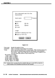
When "Read in which the Canon Scanner Test is installed exceeds above file capacity. 5 - 14 COPYRIGHT © 2000 CANON INC. File capacity is as follows. 75 dpi : Approx. 1.6 MByte 150 dpi : Approx. 6.5 MByte 300 dpi : Approx. 26.2 MByte 600 dpi : Approx. 104.9 ... that the available disk space on the HDD in memory (no file)" is selected, scanned image is read into the memory, then abandoned after readout. CANOSCAN N650U/N656U/N1220U REV.0 JUNE 2000 PRINTED IN JAPAN (IMPRIME AU JAPON) CHAPTER 5 Figure 5-14 * Scan count : Specify the number of scan. * Resolution : Select a ...
When "Read in which the Canon Scanner Test is installed exceeds above file capacity. 5 - 14 COPYRIGHT © 2000 CANON INC. File capacity is as follows. 75 dpi : Approx. 1.6 MByte 150 dpi : Approx. 6.5 MByte 300 dpi : Approx. 26.2 MByte 600 dpi : Approx. 104.9 ... that the available disk space on the HDD in memory (no file)" is selected, scanned image is read into the memory, then abandoned after readout. CANOSCAN N650U/N656U/N1220U REV.0 JUNE 2000 PRINTED IN JAPAN (IMPRIME AU JAPON) CHAPTER 5 Figure 5-14 * Scan count : Specify the number of scan. * Resolution : Select a ...

Service Manual
Page 74
...sensor. Cause 2 : Faulty drive motor/faulty home position sensor. Cause 5 : Faulty main PCB. Corrective Action : Unlock the carriage lock. CANOSCAN N650U/N656U/N1220U REV.0 JUNE 2000 PRINTED IN JAPAN (IMPRIME AU JAPON) 5 - 15 Cause 2 : Scanner is not detected by the host computer..... Cause 1 : Carriage lock is normal, replace the flat cable. If it is locked. Corrective action : Install the device driver. Cause 3 : Faulty flat cable. Cause : Canon Scanner Test is started , "Unable to use. CHAPTER 5 4. Cause 1 : Device driver for error messages which...
...sensor. Cause 2 : Faulty drive motor/faulty home position sensor. Cause 5 : Faulty main PCB. Corrective Action : Unlock the carriage lock. CANOSCAN N650U/N656U/N1220U REV.0 JUNE 2000 PRINTED IN JAPAN (IMPRIME AU JAPON) 5 - 15 Cause 2 : Scanner is not detected by the host computer..... Cause 1 : Carriage lock is normal, replace the flat cable. If it is locked. Corrective action : Install the device driver. Cause 3 : Faulty flat cable. Cause : Canon Scanner Test is started , "Unable to use. CHAPTER 5 4. Cause 1 : Device driver for error messages which...


