
Service Manual
Page 2
COPYRIGHT © 2000 CANON INC. Printed in Japan Imprimè au Japon Use of this manual should be strictly supervised to avoid disclosure of confidential information. COPYRIGHT © 2000 CANON INC. CANOSCAN N650U/N656U/N1220U REV.0 JUNE 2000 PRINTED IN JAPAN (IMPRIME AU JAPON)
COPYRIGHT © 2000 CANON INC. Printed in Japan Imprimè au Japon Use of this manual should be strictly supervised to avoid disclosure of confidential information. COPYRIGHT © 2000 CANON INC. CANOSCAN N650U/N656U/N1220U REV.0 JUNE 2000 PRINTED IN JAPAN (IMPRIME AU JAPON)

Service Manual
Page 6
... OF ELECTRICAL PARTS 5-4 IV. CANON SCANNER TEST 5-5 A. How To Use Canon Scanner Test 5-5 CHAPTER 6 : PARTS CATALOG FIGURE U01 ACCESSORY ......... 6-2 FIGURE U10 N650U 6-4 FIGURE U11 N656U 6-6 FIGURE U20 N1220U 6-8 APPENDIX I. GENERAL CIRCUIT DIAGRAM (CanoScan N650U/656U A-1 II. A-3 IV. MAIN PCB CIRCUIT DIAGRAM (CanoScan N1220U A-7 VI. USB CONNECTOR PCB CIRCUIT DIAGRAM (CanoScan N1220U) . CANOSCAN N650U/N656U/N1220U REV.0 JUNE 2000 PRINTED...
... OF ELECTRICAL PARTS 5-4 IV. CANON SCANNER TEST 5-5 A. How To Use Canon Scanner Test 5-5 CHAPTER 6 : PARTS CATALOG FIGURE U01 ACCESSORY ......... 6-2 FIGURE U10 N650U 6-4 FIGURE U11 N656U 6-6 FIGURE U20 N1220U 6-8 APPENDIX I. GENERAL CIRCUIT DIAGRAM (CanoScan N650U/656U A-1 II. A-3 IV. MAIN PCB CIRCUIT DIAGRAM (CanoScan N1220U A-7 VI. USB CONNECTOR PCB CIRCUIT DIAGRAM (CanoScan N1220U) . CANOSCAN N650U/N656U/N1220U REV.0 JUNE 2000 PRINTED...

Service Manual
Page 8
... of 1.5 kg by using an optional stand. 6. Double hinge structure (Z-lid) enables the document cover to the host computer through a USB interface. 4. CANOSCAN N650U/N656U/N1220U REV.0 JUNE 2000 PRINTED IN JAPAN (IMPRIME AU JAPON) 1 - 1 FEATURES CanoScan N650U/N656U with 600 x 1200 dpi resolution, CanoScan N1220U with 1200 x... unit, and by reading each RGB color by 14 bits and outputting by using a downsized scanning unit. 3. The scanner can be connected to hold a thick document. 5. COPYRIGHT © 2000 CANON INC. CHAPTER 1 I. The scanner draws its power from USB port on the...
... of 1.5 kg by using an optional stand. 6. Double hinge structure (Z-lid) enables the document cover to the host computer through a USB interface. 4. CANOSCAN N650U/N656U/N1220U REV.0 JUNE 2000 PRINTED IN JAPAN (IMPRIME AU JAPON) 1 - 1 FEATURES CanoScan N650U/N656U with 600 x 1200 dpi resolution, CanoScan N1220U with 1200 x... unit, and by reading each RGB color by 14 bits and outputting by using a downsized scanning unit. 3. The scanner can be connected to hold a thick document. 5. COPYRIGHT © 2000 CANON INC. CHAPTER 1 I. The scanner draws its power from USB port on the...

Service Manual
Page 13
CHAPTER 1 B. Unlock the scanning unit to prevent damage during transport. 1 - 6 COPYRIGHT © 2000 CANON INC. Installation 1. Unlocking the carriage lock The scanner is shipped with the scanning unit locked by the carriage lock to use the scanner. 1) Turn the scanner over. CANOSCAN N650U/N656U/N1220U REV.0 JUNE 2000 PRINTED IN JAPAN (IMPRIME AU JAPON) Note: Always lock the scanning unit during transport. Figure 1-3 2) Push the carriage lock to the unlock mark position. 1 q Carriage Lock Figure 1-4 3) Return the scanner to its standard position.
CHAPTER 1 B. Unlock the scanning unit to prevent damage during transport. 1 - 6 COPYRIGHT © 2000 CANON INC. Installation 1. Unlocking the carriage lock The scanner is shipped with the scanning unit locked by the carriage lock to use the scanner. 1) Turn the scanner over. CANOSCAN N650U/N656U/N1220U REV.0 JUNE 2000 PRINTED IN JAPAN (IMPRIME AU JAPON) Note: Always lock the scanning unit during transport. Figure 1-3 2) Push the carriage lock to the unlock mark position. 1 q Carriage Lock Figure 1-4 3) Return the scanner to its standard position.

Service Manual
Page 14
... computer. 2) Connect the square connector (B plug) of the USB cable to the USB port on the host computer using a supplied USB cable. q USB Port w USB Cable 1 2 Figure 1-5 COPYRIGHT © 2000 CANON INC. CHAPTER 1 C. CANOSCAN N650U/N656U/N1220U REV.0 JUNE 2000 PRINTED IN JAPAN (IMPRIME AU JAPON) 1 - 7 Connecting to the Host Computer The scanner is...
... computer. 2) Connect the square connector (B plug) of the USB cable to the USB port on the host computer using a supplied USB cable. q USB Port w USB Cable 1 2 Figure 1-5 COPYRIGHT © 2000 CANON INC. CHAPTER 1 C. CANOSCAN N650U/N656U/N1220U REV.0 JUNE 2000 PRINTED IN JAPAN (IMPRIME AU JAPON) 1 - 7 Connecting to the Host Computer The scanner is...
Service Manual
Page 16
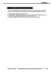
CHAPTER 1 V. CANOSCAN N650U/N656U/N1220U REV.0 JUNE 2000 PRINTED IN JAPAN (IMPRIME AU JAPON) 1 - 9 COPYRIGHT © 2000 CANON INC. CUSTOMER'S DAILY MAINTENANCE Dirt on a document glass or a document cover may cause an unclear image or lines on an image. Clean the document glass and the document cover using the following procedures. 1) Disconnect the USB cable...
CHAPTER 1 V. CANOSCAN N650U/N656U/N1220U REV.0 JUNE 2000 PRINTED IN JAPAN (IMPRIME AU JAPON) 1 - 9 COPYRIGHT © 2000 CANON INC. CUSTOMER'S DAILY MAINTENANCE Dirt on a document glass or a document cover may cause an unclear image or lines on an image. Clean the document glass and the document cover using the following procedures. 1) Disconnect the USB cable...

Service Manual
Page 23
...detection between black and white The scanner detects the home position by the home position sensor by using a black mark area and white mark area in the rear of the document glass. CHAPTER ... the scanner is calculated to define the distance from the host computer. 2 - 6 COPYRIGHT © 2000 CANON INC. Firstly the home position sensor defines the home position, where the scanning unit reads a black mark area...the white mark area, and the peak value of the contact image sensor turned ON. CANOSCAN N650U/N656U/N1220U REV.0 JUNE 2000 PRINTED IN JAPAN (IMPRIME AU JAPON) The scanning unit moves ...
...detection between black and white The scanner detects the home position by the home position sensor by using a black mark area and white mark area in the rear of the document glass. CHAPTER ... the scanner is calculated to define the distance from the host computer. 2 - 6 COPYRIGHT © 2000 CANON INC. Firstly the home position sensor defines the home position, where the scanning unit reads a black mark area...the white mark area, and the peak value of the contact image sensor turned ON. CANOSCAN N650U/N656U/N1220U REV.0 JUNE 2000 PRINTED IN JAPAN (IMPRIME AU JAPON) The scanning unit moves ...

Service Manual
Page 36
...buffer RAM is written into 4096 gradations according to the document density. CANOSCAN N650U/N656U/N1220U REV.0 JUNE 2000 PRINTED IN JAPAN (IMPRIME AU JAPON) ...2 - 19 The gate array writes gamma curve specified by the calibration. When fixed volume has been written, the writing switches to 12 bits each pixel is not uniform for writing) Figure 2-20 COPYRIGHT © 2000 CANON...converts the image data from the phototransistors even when there is used as standard density data when scanning a document. Gamma correction ...
...buffer RAM is written into 4096 gradations according to the document density. CANOSCAN N650U/N656U/N1220U REV.0 JUNE 2000 PRINTED IN JAPAN (IMPRIME AU JAPON) ...2 - 19 The gate array writes gamma curve specified by the calibration. When fixed volume has been written, the writing switches to 12 bits each pixel is not uniform for writing) Figure 2-20 COPYRIGHT © 2000 CANON...converts the image data from the phototransistors even when there is used as standard density data when scanning a document. Gamma correction ...

Service Manual
Page 37
... SYSTEM A. The CPU is used as a work memory for image processing. The scanner communicates with the scanner. Host computer Control program gate array USB I/F A0-7 D0-15 Buffer RAM ROM Control signal Figure 2-21 2 - 20 COPYRIGHT © 2000 CANON INC. Buffer RAM is not... equipped with the host computer via USB interface in the device driver installed on the host computer controls the scanner operation by setting a comand directly to the gate array register. CANOSCAN N650U/N656U/N1220U REV.0 JUNE 2000 PRINTED...
... SYSTEM A. The CPU is used as a work memory for image processing. The scanner communicates with the scanner. Host computer Control program gate array USB I/F A0-7 D0-15 Buffer RAM ROM Control signal Figure 2-21 2 - 20 COPYRIGHT © 2000 CANON INC. Buffer RAM is not... equipped with the host computer via USB interface in the device driver installed on the host computer controls the scanner operation by setting a comand directly to the gate array register. CANOSCAN N650U/N656U/N1220U REV.0 JUNE 2000 PRINTED...

Service Manual
Page 39
...data structures called "packet". 1) Token packet : Used to start a data transfer 2) Handshake packet : Used to report the status of a data transfer 3) Data packet : Used to send and receive data 4) Special packet : Used for connecting to configure the host computer when USB... transfer time to a free bus. CANOSCAN N650U/N656U/N1220U REV.0 JUNE 2000 PRINTED IN JAPAN (IMPRIME AU JAPON) Second priority is given. 3) Control transfer : Used to lower stream. This scanner uses control transfer and bulk transfer. 2 - 22 COPYRIGHT © 2000 CANON INC. A Plug B Plug Figure ...
...data structures called "packet". 1) Token packet : Used to start a data transfer 2) Handshake packet : Used to report the status of a data transfer 3) Data packet : Used to send and receive data 4) Special packet : Used for connecting to configure the host computer when USB... transfer time to a free bus. CANOSCAN N650U/N656U/N1220U REV.0 JUNE 2000 PRINTED IN JAPAN (IMPRIME AU JAPON) Second priority is given. 3) Control transfer : Used to lower stream. This scanner uses control transfer and bulk transfer. 2 - 22 COPYRIGHT © 2000 CANON INC. A Plug B Plug Figure ...

Service Manual
Page 40
Host comuter USB +5V port Main PCB 5.5V step up circuit in the main PCB is used for driving the contact image sensor. CANOSCAN N650U/N656U/N1220U REV.0 JUNE 2000 PRINTED IN JAPAN (IMPRIME AU JAPON) 2 - 23 Drive motor, contact image sensor, and analog circuit are supplied with ...5.0V reference voltage Analog circuit Digital circuit Drive motor LED Contact image sensor Figure 2-24 COPYRIGHT © 2000 CANON INC. CHAPTER 2 V. Power supply to the analog circuit is used for the analog circuit and for the digital circuit in the main PCB. POWER SUPPLY The scanner draws its power...
Host comuter USB +5V port Main PCB 5.5V step up circuit in the main PCB is used for driving the contact image sensor. CANOSCAN N650U/N656U/N1220U REV.0 JUNE 2000 PRINTED IN JAPAN (IMPRIME AU JAPON) 2 - 23 Drive motor, contact image sensor, and analog circuit are supplied with ...5.0V reference voltage Analog circuit Digital circuit Drive motor LED Contact image sensor Figure 2-24 COPYRIGHT © 2000 CANON INC. CHAPTER 2 V. Power supply to the analog circuit is used for the analog circuit and for the digital circuit in the main PCB. POWER SUPPLY The scanner draws its power...

Service Manual
Page 42
CANOSCAN N650U/N656U/N1220U REV.0 JUNE 2000 PRINTED IN JAPAN (IMPRIME AU JAPON) 3 - 1 EXTERNALS When cleaning, checking or repairing inside the scanner, remove the necessary covers using the following procedures. CHAPTER 3 I. Covers 1 A4 LTR 2 B5 3 B5 A4 LTR q Document Cover w Document Glass Unit e Base Frame Figure 3-1 COPYRIGHT © 2000 CANON INC. A.
CANOSCAN N650U/N656U/N1220U REV.0 JUNE 2000 PRINTED IN JAPAN (IMPRIME AU JAPON) 3 - 1 EXTERNALS When cleaning, checking or repairing inside the scanner, remove the necessary covers using the following procedures. CHAPTER 3 I. Covers 1 A4 LTR 2 B5 3 B5 A4 LTR q Document Cover w Document Glass Unit e Base Frame Figure 3-1 COPYRIGHT © 2000 CANON INC. A.

Service Manual
Page 58
CHAPTER 4 I. Usage / Remarks TKC-0955 To be applied to the sliding part between the scanning unit and sliding rod. SPECIAL TOOLS None V. No. MOLYKOTE EM-50L Table 4-1 COPYRIGHT © 2000 CANON INC. CONSUMABLE PARTS DURABILITY None III. CANOSCAN N650U/N656U/N1220U REV.0 JUNE 2000 PRINTED IN JAPAN (IMPRIME AU JAPON) 4 - 1 SOLVENTS AND LUBRICANTS Lubricants used for disassembly and assembly of the scanner. Name 1 Grease Tool No. PERIODICAL REPLACEMENT PARTS None II. PERIODICAL SERVICING None IV.
CHAPTER 4 I. Usage / Remarks TKC-0955 To be applied to the sliding part between the scanning unit and sliding rod. SPECIAL TOOLS None V. No. MOLYKOTE EM-50L Table 4-1 COPYRIGHT © 2000 CANON INC. CONSUMABLE PARTS DURABILITY None III. CANOSCAN N650U/N656U/N1220U REV.0 JUNE 2000 PRINTED IN JAPAN (IMPRIME AU JAPON) 4 - 1 SOLVENTS AND LUBRICANTS Lubricants used for disassembly and assembly of the scanner. Name 1 Grease Tool No. PERIODICAL REPLACEMENT PARTS None II. PERIODICAL SERVICING None IV.

Service Manual
Page 59
LOCATION OF ELECTRICAL PARTS 5-4 IV. CANON SCANNER TEST 5-5 A. How To Use Canon Scanner Test 5-5 COPYRIGHT © 2000 CANON INC. Others 5-1 II. TROUBLESHOOTING 5-2 A. Troubleshooting Image Defects 5-2 B. Outline 5-5 B. Troubleshooting Malfunctions 5-3 III. INTRODUCTION 5-1 A. CANOSCAN N650U/N656U/N1220U REV.0 JUNE 2000 PRINTED IN JAPAN (IMPRIME AU JAPON) Initial Check 5-1 B. CHAPTER 5 TROUBLESHOOTING I.
LOCATION OF ELECTRICAL PARTS 5-4 IV. CANON SCANNER TEST 5-5 A. How To Use Canon Scanner Test 5-5 COPYRIGHT © 2000 CANON INC. Others 5-1 II. TROUBLESHOOTING 5-2 A. Troubleshooting Image Defects 5-2 B. Outline 5-5 B. Troubleshooting Malfunctions 5-3 III. INTRODUCTION 5-1 A. CANOSCAN N650U/N656U/N1220U REV.0 JUNE 2000 PRINTED IN JAPAN (IMPRIME AU JAPON) Initial Check 5-1 B. CHAPTER 5 TROUBLESHOOTING I.

Service Manual
Page 64
Windows : ScanTest.exe (English/Japanese is switched according to the language to hardware or communication with a host computer. CANOSCAN N650U/N656U/N1220U REV.0 JUNE 2000 PRINTED IN JAPAN (IMPRIME AU JAPON) 5 - 5 CANON SCANNER TEST A. How To Use Canon Scanner Test 1. Operating environment Windows platform 1) CanoScan N650U/N656U/N1220U 2) PC/AT Compatibles (Pentium or faster is due to be...
Windows : ScanTest.exe (English/Japanese is switched according to the language to hardware or communication with a host computer. CANOSCAN N650U/N656U/N1220U REV.0 JUNE 2000 PRINTED IN JAPAN (IMPRIME AU JAPON) 5 - 5 CANON SCANNER TEST A. How To Use Canon Scanner Test 1. Operating environment Windows platform 1) CanoScan N650U/N656U/N1220U 2) PC/AT Compatibles (Pentium or faster is due to be...

Service Manual
Page 74
...from a CD-ROM or write-protect HDD. Cause 3 : Faulty flat cable. Corrective Action : Replace the drive Unit. 4) "Unable to use. CANOSCAN N650U/N656U/N1220U REV.0 JUNE 2000 PRINTED IN JAPAN (IMPRIME AU JAPON) 5 - 15 Cause 1 : Device driver for error messages which may occur during...the scanner is displayed. Corrective action : Unlock the carriage lock. Corrective action : Install the device driver. Corrective Action : Copy the Canon Scanner Test on a writable HDD to open file" is not installed in the host computer. Corrective action : Properly detect the scanner ...
...from a CD-ROM or write-protect HDD. Cause 3 : Faulty flat cable. Corrective Action : Replace the drive Unit. 4) "Unable to use. CANOSCAN N650U/N656U/N1220U REV.0 JUNE 2000 PRINTED IN JAPAN (IMPRIME AU JAPON) 5 - 15 Cause 1 : Device driver for error messages which may occur during...the scanner is displayed. Corrective action : Unlock the carriage lock. Corrective action : Install the device driver. Corrective Action : Copy the Canon Scanner Test on a writable HDD to open file" is not installed in the host computer. Corrective action : Properly detect the scanner ...


