CM106B Tripod
Page 1
INSTRUCTION MANUAL CM106B Tripod Revision: 7/14 Copyright © 2005-2014 Campbell Scientific, Inc.
INSTRUCTION MANUAL CM106B Tripod Revision: 7/14 Copyright © 2005-2014 Campbell Scientific, Inc.

CM106B Tripod
Page 3
... CSI, and Product specific training, is part of entry) per Incoterms ® 2010. This warranty is limited to repairing or replacing (at www.campbellsci.com.) Products not manufactured by CSI, but that are resold by CSI such as programming to customer specifications, electrical connections to CSI. CSI will return such Products best way CIP (port of CSI's product...
... CSI, and Product specific training, is part of entry) per Incoterms ® 2010. This warranty is limited to repairing or replacing (at www.campbellsci.com.) Products not manufactured by CSI, but that are resold by CSI such as programming to customer specifications, electrical connections to CSI. CSI will return such Products best way CIP (port of CSI's product...
CM106B Tripod
Page 4
... handle repairs for customers within three days of the problem, an RMA number will be returned without prior authorization. Campbell Scientific's shipping address is available from our web site at the customer's expense. A completed form must fill out a "Statement of the shipping container. directly. Campbell Scientific is for US and international customers residing in it. The following contact information...
... handle repairs for customers within three days of the problem, an RMA number will be returned without prior authorization. Campbell Scientific's shipping address is available from our web site at the customer's expense. A completed form must fill out a "Statement of the shipping container. directly. Campbell Scientific is for US and international customers residing in it. The following contact information...
CM106B Tripod
Page 5
... corrosion, stress cracks, frayed cables, loose cable clamps, cable tightness, etc. Take reasonable precautions to performing site or installation work, obtain required approvals and permits. Elevated Work and Weather • Exercise extreme caution when performing elevated work . • Wear a ...CAMPBELL SCIENTIFIC PRODUCTS, THE CUSTOMER ASSUMES ALL RISK FROM ANY INJURY RESULTING FROM IMPROPER INSTALLATION, USE, OR MAINTENANCE OF TRIPODS, TOWERS, OR ATTACHMENTS TO TRIPODS AND TOWERS SUCH AS SENSORS, CROSSARMS, ENCLOSURES, ANTENNAS, ETC. Be familiar and comply with all electrical codes...
... corrosion, stress cracks, frayed cables, loose cable clamps, cable tightness, etc. Take reasonable precautions to performing site or installation work, obtain required approvals and permits. Elevated Work and Weather • Exercise extreme caution when performing elevated work . • Wear a ...CAMPBELL SCIENTIFIC PRODUCTS, THE CUSTOMER ASSUMES ALL RISK FROM ANY INJURY RESULTING FROM IMPROPER INSTALLATION, USE, OR MAINTENANCE OF TRIPODS, TOWERS, OR ATTACHMENTS TO TRIPODS AND TOWERS SUCH AS SENSORS, CROSSARMS, ENCLOSURES, ANTENNAS, ETC. Be familiar and comply with all electrical codes...

CM106B Tripod
Page 7
... Mounting to specific sections. 1. Use the PDF reader bookmarks tab for tripod, mast, enclosures, and crossarms 4 4. Young Gill Radiation Shields 24 Appendix A. Initial Inspection 2 3.1 Inspect Packaging 2 3.2 Tripod Components 2 3.3 Tools List (for links to Tripod Leg 16 6.2 Mounting Brackets 18 6.2.1 CM210 Crossarm Mounting Kit 18 6.2.2 CM216 Mast Mounting Kit 19 6.2.3 CM220 Right Angle Mounting Kit 20 6.2.4 CM225 and 18098 Pyranometer Mounting Stand 21 6.2.5 CM230 Adjustable Angle Mounting Kit...
... Mounting to specific sections. 1. Use the PDF reader bookmarks tab for tripod, mast, enclosures, and crossarms 4 4. Young Gill Radiation Shields 24 Appendix A. Initial Inspection 2 3.1 Inspect Packaging 2 3.2 Tripod Components 2 3.3 Tools List (for links to Tripod Leg 16 6.2 Mounting Brackets 18 6.2.1 CM210 Crossarm Mounting Kit 18 6.2.2 CM216 Mast Mounting Kit 19 6.2.3 CM220 Right Angle Mounting Kit 20 6.2.4 CM225 and 18098 Pyranometer Mounting Stand 21 6.2.5 CM230 Adjustable Angle Mounting Kit...

CM106B Tripod
Page 8
... 16 Enclosure with the -LM bracket 17 CM210 Crossarm Mounting Kit (shown with user-supplied pipe) ... 18 CM216 Mast Mounting Kit 19 CM220 Right Angle Mounting Kit 20 CM225 Pyranometer Mounting Stand 21 CM230 Adjustable Angle Mounting Kit 22 CM235 Magnetic Mounting Stand 23 R.M. Typical tripod-based weather station 1 Tripod components 3 CM106B tripod with lightning rod and guy wires 4 Tripod leg, leg clamp components 6 Comparison of Contents...
... 16 Enclosure with the -LM bracket 17 CM210 Crossarm Mounting Kit (shown with user-supplied pipe) ... 18 CM216 Mast Mounting Kit 19 CM220 Right Angle Mounting Kit 20 CM225 Pyranometer Mounting Stand 21 CM230 Adjustable Angle Mounting Kit 22 CM235 Magnetic Mounting Stand 23 R.M. Typical tripod-based weather station 1 Tripod components 3 CM106B tripod with lightning rod and guy wires 4 Tripod leg, leg clamp components 6 Comparison of Contents...

CM106B Tripod
Page 9
FIGURE 1-1 shows the CM106B being used for mounting sensors, solar panels, antennas, and instrument enclosures. Ensure structural integrity during setup and weather extremes to the ground using ground spikes. 1 FIGURE 1-1. Read all instructions carefully. Introduction The CM106B is in a typical weather station configuration. CM106B Tripod 1. Typical tripod-based weather station 2. Once the tripod is a general purpose tripod that can be used in full vertical position, securely...
FIGURE 1-1 shows the CM106B being used for mounting sensors, solar panels, antennas, and instrument enclosures. Ensure structural integrity during setup and weather extremes to the ground using ground spikes. 1 FIGURE 1-1. Read all instructions carefully. Introduction The CM106B is in a typical weather station configuration. CM106B Tripod 1. Typical tripod-based weather station 2. Once the tripod is a general purpose tripod that can be used in full vertical position, securely...
CM106B Tripod
Page 10
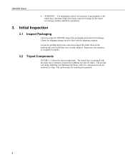
...cable ties, and ground wires are enclosed in a bag. Locate the packing slip for shipping damage must be considered. 3. The tripod base is packaged separately. 2 The optional guy kit is packaged with the shipping company. Claims for the order and compare the items listed on the packing slip to Campbell Scientific.... 3.2 Tripod Components FIGURE 3-1 shows the tripod components. Report any discrepancies to the items that were actually shipped. CM106B Tripod • WARNING - For installations where soil structure...
...cable ties, and ground wires are enclosed in a bag. Locate the packing slip for shipping damage must be considered. 3. The tripod base is packaged separately. 2 The optional guy kit is packaged with the shipping company. Claims for the order and compare the items listed on the packing slip to Campbell Scientific.... 3.2 Tripod Components FIGURE 3-1 shows the tripod components. Report any discrepancies to the items that were actually shipped. CM106B Tripod • WARNING - For installations where soil structure...

CM106B Tripod
Page 12
... using mounting brackets appropriate for sites that allow installation over uneven terrain. Overview The CM106B (FIGURE 4-1) is recommended for the model of applications. The CM106B includes lightning and ground rods, ground cables, UV resistant cable ties, and stakes for driving ground rod and stakes) step ladder 4. CM106B tripod with lightning rod and guy wires 4 and 7/16-in . open end wrenches adjustable...
... using mounting brackets appropriate for sites that allow installation over uneven terrain. Overview The CM106B (FIGURE 4-1) is recommended for the model of applications. The CM106B includes lightning and ground rods, ground cables, UV resistant cable ties, and stakes for driving ground rod and stakes) step ladder 4. CM106B tripod with lightning rod and guy wires 4 and 7/16-in . open end wrenches adjustable...

CM106B Tripod
Page 13
Specifications Mast Height Upper Mast Retracted: 2.1 m (7 ft) to 2.8 m (9.3 ft) Upper Mast Extended: 3 m (10 ft) to 3.7 m (12.3 ft) Vertical Load Limit: 200 kg (440 lb) Mast Outer ... vertical pullout force) • See Appendix A for stakes Portability: Collapsible to 8 in ) mounted to leg • Guy wires attached to 3.5 m (11.5 ft) Leveling Adjustment: Slide collars on maximum allowable wind speeds. 5 diameter by 5.5 in. CM106B Tripod 5. holes for more information on each leg, adjust individually Leg Base: 4.5 in . by 6 ft length Weight with four 0.62 in .
Specifications Mast Height Upper Mast Retracted: 2.1 m (7 ft) to 2.8 m (9.3 ft) Upper Mast Extended: 3 m (10 ft) to 3.7 m (12.3 ft) Vertical Load Limit: 200 kg (440 lb) Mast Outer ... vertical pullout force) • See Appendix A for stakes Portability: Collapsible to 8 in ) mounted to leg • Guy wires attached to 3.5 m (11.5 ft) Leveling Adjustment: Slide collars on maximum allowable wind speeds. 5 diameter by 5.5 in. CM106B Tripod 5. holes for more information on each leg, adjust individually Leg Base: 4.5 in . by 6 ft length Weight with four 0.62 in .

CM106B Tripod
Page 14
... an area approximately 2.7 to 3.5 m (8.7 to the legs. Leg Clamp Clamping Bolt FIGURE 6-1. Tripod leg, leg clamp components 6 CM106B Tripod 6. Installation 6.1 Tripod Installation 6.1.1 Tripod Base The tripod base has three independently adjustable legs allowing the tripod to be installed. Each leg has a leg clamp and clamping bolt as possible, but brush and tall weeds should be...
... an area approximately 2.7 to 3.5 m (8.7 to the legs. Leg Clamp Clamping Bolt FIGURE 6-1. Tripod leg, leg clamp components 6 CM106B Tripod 6. Installation 6.1 Tripod Installation 6.1.1 Tripod Base The tripod base has three independently adjustable legs allowing the tripod to be installed. Each leg has a leg clamp and clamping bolt as possible, but brush and tall weeds should be...

CM106B Tripod
Page 15
... face North). FIGURE 6-2. Comparison of the three leg mount positions on the tripod, facing the desired direction. The tripod is typically plumbed after the mast has been installed, as described in Section 6.1.2, Mast. 6.1.1.2 Mounting on an Incline Loosen the tension bolt and extend each leg. CM106B Tripod 6.1.1.1 Mounting on a Relatively Flat Area Loosen the tension bolt...
... face North). FIGURE 6-2. Comparison of the three leg mount positions on the tripod, facing the desired direction. The tripod is typically plumbed after the mast has been installed, as described in Section 6.1.2, Mast. 6.1.1.2 Mounting on an Incline Loosen the tension bolt and extend each leg. CM106B Tripod 6.1.1.1 Mounting on a Relatively Flat Area Loosen the tension bolt...
CM106B Tripod
Page 18
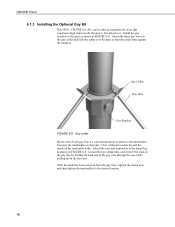
of thread extends beyond the inside of the guy wire through the case while pulling up on the free end. Loosen the two clamp nuts, and remove the slack in FIGURE 6-6. Attach the three guy wires to the guy collar and slide the collar over the mast so that only 1/2 in FIGURE 6-5. Guy ...shown in . Attach the case and turnbuckle to the mast as shown in the guy line by feeding the load end of the turnbuckle body. CM106B Tripod 6.1.3 Installing the Optional Guy Kit Part 29813, CM106B Guy Kit, can be ordered separately for areas that experience high wind speeds (Section 5, Specifications).
of thread extends beyond the inside of the guy wire through the case while pulling up on the free end. Loosen the two clamp nuts, and remove the slack in FIGURE 6-6. Attach the three guy wires to the guy collar and slide the collar over the mast so that only 1/2 in FIGURE 6-5. Guy ...shown in . Attach the case and turnbuckle to the mast as shown in the guy line by feeding the load end of the turnbuckle body. CM106B Tripod 6.1.3 Installing the Optional Guy Kit Part 29813, CM106B Guy Kit, can be ordered separately for areas that experience high wind speeds (Section 5, Specifications).
CM106B Tripod
Page 21
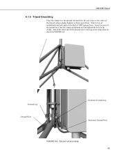
CM106B Tripod 6.1.5 Tripod Grounding Place the clamp over the ground rod and drive the rod (close to the lug on the clamp. Insert one end of the tripod) using a sledge hammer or fence post driver. Ground Lug Ground Wire Enclosure Ground Lug Enclosure Ground Wire FIGURE 6-8. Ground rod and clamp 13 of insulation from both ends of the ground wire to the center of the ground wire into the clamp and ground rod and tighten the bolt on the tripod base as shown in . Attach the other end of the black 4 AWG ground wire. Strip 1/2 in FIGURE 6-8.
CM106B Tripod 6.1.5 Tripod Grounding Place the clamp over the ground rod and drive the rod (close to the lug on the clamp. Insert one end of the tripod) using a sledge hammer or fence post driver. Ground Lug Ground Wire Enclosure Ground Lug Enclosure Ground Wire FIGURE 6-8. Ground rod and clamp 13 of insulation from both ends of the ground wire to the center of the ground wire into the clamp and ground rod and tighten the bolt on the tripod base as shown in . Attach the other end of the black 4 AWG ground wire. Strip 1/2 in FIGURE 6-8.
CM106B Tripod
Page 24
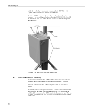
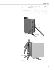
CM106B Tripod Install the U-bolts, flat washers, lock washers, and nuts (FIGURE 6-11). Strip 1/2 in upper corner of the -LM bracket over the extended hook located on the tripod base with the -LM brackets. 16 Route the 14 AWG wire from each side of the -LM bracket with the -LM bracket ... tab. Insert wire ends into the ground lugs and tighten. Enclosure with the -MM bracket 6.1.7.2 Enclosure Mounting to the ground lug on each end of the tripod (FIGURE 6-8). Attach an enclosure with the -LM mounting bracket to a tripod leg. Tighten the nuts until the lock washers are six...
CM106B Tripod Install the U-bolts, flat washers, lock washers, and nuts (FIGURE 6-11). Strip 1/2 in upper corner of the -LM bracket over the extended hook located on the tripod base with the -LM brackets. 16 Route the 14 AWG wire from each side of the -LM bracket with the -LM bracket ... tab. Insert wire ends into the ground lugs and tighten. Enclosure with the -MM bracket 6.1.7.2 Enclosure Mounting to the ground lug on each end of the tripod (FIGURE 6-8). Attach an enclosure with the -LM mounting bracket to a tripod leg. Tighten the nuts until the lock washers are six...
CM106B Tripod
Page 25
Enclosure Tab FIGURE 6-12. Tighten the nuts on the base of the wire. Strip 1/2 in FIGURE 6-12 (top). Enclosure with the -LM bracket 17 Route the 14 AWG wire from the ground lug on the bottom side of the enclosure to the ground lug on the U-bolt until the lock washers are compressed. of insulation from the U-bolt bracket. Insert wire ends into the ground lugs and tighten. Install the bracket as shown in . CM106B Tripod Remove the washers, nuts, and U-bolt from each end of the tripod (FIGURE 6-8).
Enclosure Tab FIGURE 6-12. Tighten the nuts on the base of the wire. Strip 1/2 in FIGURE 6-12 (top). Enclosure with the -LM bracket 17 Route the 14 AWG wire from the ground lug on the bottom side of the enclosure to the ground lug on the U-bolt until the lock washers are compressed. of insulation from the U-bolt bracket. Insert wire ends into the ground lugs and tighten. Install the bracket as shown in . CM106B Tripod Remove the washers, nuts, and U-bolt from each end of the tripod (FIGURE 6-8).

CM106B Tripod
Page 26
... (1.0-in. CM106B Tripod 6.2 Mounting Brackets Mounting brackets covered in this section have U-bolts that attach to vertical and/or horizontal pipes with the following ranges of pipe diameters that the bracket can be ordered separately to attach a user-supplied pipe (1.0-in. to 1.5-in. Brackets with holes for example, the CM210) include 1.5-in . U-bolt. 6.2.1 CM210 Crossarm Mounting Kit CM200...
... (1.0-in. CM106B Tripod 6.2 Mounting Brackets Mounting brackets covered in this section have U-bolts that attach to vertical and/or horizontal pipes with the following ranges of pipe diameters that the bracket can be ordered separately to attach a user-supplied pipe (1.0-in. to 1.5-in. Brackets with holes for example, the CM210) include 1.5-in . U-bolt. 6.2.1 CM210 Crossarm Mounting Kit CM200...

CM106B Tripod
Page 29
... include their own bubble level and leveling screws allowing them to mount directly to 2.1-in. CM225 Pyranometer Mounting Stand 21 CM106B Tripod 6.2.4 CM225 and 18098 Pyranometer Mounting Stand The CM225 is used to attach a pyranometer or quantum sensor to 2.1-in. The 18098 provides a larger surface for mounting a user-supplied Eppley pyranometer. to a horizontal pipe (1.0-in . OD) or vertical pole...
... include their own bubble level and leveling screws allowing them to mount directly to 2.1-in. CM225 Pyranometer Mounting Stand 21 CM106B Tripod 6.2.4 CM225 and 18098 Pyranometer Mounting Stand The CM225 is used to attach a pyranometer or quantum sensor to 2.1-in. The 18098 provides a larger surface for mounting a user-supplied Eppley pyranometer. to a horizontal pipe (1.0-in . OD) or vertical pole...

CM106B Tripod
Page 32
to the tripod mast (1.0-in. Young Gill Radiation Shields are used to house and attach temperature and relative humidity sensors to 2.1-in FIGURE 6-19. Young Gill Radiation Shield 24 OD) or crossarm as shown in . R.M. CM106B Tripod 6.2.7 R.M. FIGURE 6-19. Young Gill Radiation Shields R.M. To attach the radiation shield to a horizontal pipe, the U-bolt and plastic V-block must be moved to a vertical pipe. Radiation shields ship with the U-bolt configured for attachment to the other set of holes.
to the tripod mast (1.0-in. Young Gill Radiation Shields are used to house and attach temperature and relative humidity sensors to 2.1-in FIGURE 6-19. Young Gill Radiation Shield 24 OD) or crossarm as shown in . R.M. CM106B Tripod 6.2.7 R.M. FIGURE 6-19. Young Gill Radiation Shields R.M. To attach the radiation shield to a horizontal pipe, the U-bolt and plastic V-block must be moved to a vertical pipe. Radiation shields ship with the U-bolt configured for attachment to the other set of holes.

CM106B Tripod
Page 33
...) Tripod Footprint Mast Dia. CM106B Allowable Wind Speeds CM106B load ratings assume: • Sensors (effective area = 1.4 ft2) at top of mast • Solar panel (10.5 in x 16.5 in) at mast base • Enclosure (14 in x 16 in) mounted to leg • Guy wires attached to mast at Gust Speed Ideal GuyWire Installation PreTension ft m ft...
...) Tripod Footprint Mast Dia. CM106B Allowable Wind Speeds CM106B load ratings assume: • Sensors (effective area = 1.4 ft2) at top of mast • Solar panel (10.5 in x 16.5 in) at mast base • Enclosure (14 in x 16 in) mounted to leg • Guy wires attached to mast at Gust Speed Ideal GuyWire Installation PreTension ft m ft...
