
Service Manual
Page 2
... clamp lifter 16 M Threading 17 Ej Needle bar 17 M Presser arm 19 M Disc clearances of main and sub tensions 20 to denim stitches 36 • List of, replacement parts 17 THOUS CHA 39
... clamp lifter 16 M Threading 17 Ej Needle bar 17 M Presser arm 19 M Disc clearances of main and sub tensions 20 to denim stitches 36 • List of, replacement parts 17 THOUS CHA 39
Service Manual
Page 35
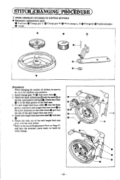
s 3. (STITCHtHiNgiNcPPAOCEOURE 0 00 T FROM ORDINARY STITCHES TO KNITTED STITCHES • Necessary replacement parts Feed cam 0 Change gear C Change gear W Work clamps L. R Needle Feed guide 0 Needle hole plate 0 0 Ni 0 ..) -CD (Procedure) When changing the number of the tack length ... arrow direction so that roller OtO is in the back groove of the bed. and have the necessary parts ready on Page 37. Install change . 0 _0 -35- be sure to the List of Replacement Parts on hand for stitch change gear W 0 with the mark ® of the feed cam. and install it with...
s 3. (STITCHtHiNgiNcPPAOCEOURE 0 00 T FROM ORDINARY STITCHES TO KNITTED STITCHES • Necessary replacement parts Feed cam 0 Change gear C Change gear W Work clamps L. R Needle Feed guide 0 Needle hole plate 0 0 Ni 0 ..) -CD (Procedure) When changing the number of the tack length ... arrow direction so that roller OtO is in the back groove of the bed. and have the necessary parts ready on Page 37. Install change . 0 _0 -35- be sure to the List of Replacement Parts on hand for stitch change gear W 0 with the mark ® of the feed cam. and install it with...
Service Manual
Page 36
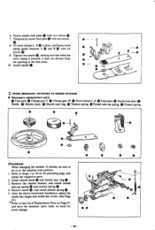
...tension spring (D. 4. After the above-mentioned installation, adjust the needle bar height and needle bar stroke. (See Page 23.) * Refer to the List of stitches, be sure to do so at the machine stop position. Fit work clamps L. R in the feed plate. 10. R 0 Feed...ca. • 4... 40 0 O • 0- --© (Procedure) When changing the number of Replacement Parts on Page 37, and have the necessary parts ready on the preceding page, and install the respective parts. 2. Temporarily fasten feed plate with two screws (D. 7. Fasten needle hole plate with two screws e •...
...tension spring (D. 4. After the above-mentioned installation, adjust the needle bar height and needle bar stroke. (See Page 23.) * Refer to the List of stitches, be sure to do so at the machine stop position. Fit work clamps L. R in the feed plate. 10. R 0 Feed...ca. • 4... 40 0 O • 0- --© (Procedure) When changing the number of Replacement Parts on Page 37, and have the necessary parts ready on the preceding page, and install the respective parts. 2. Temporarily fasten feed plate with two screws (D. 7. Fasten needle hole plate with two screws e •...
Service Manual
Page 37
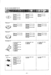
... 6 x 13 (tack width 3 mm) 153206-0-01 12 x 24 (Sunken type S) 153207-0-01 6 x 23 (tack width 3 mm) 152792-0-01 5 x 13 (tack width 2 mm) 152791-0-01 - 37 - M LIST OF REPLACEMENT PARTS Nam0vab;
... 6 x 13 (tack width 3 mm) 153206-0-01 12 x 24 (Sunken type S) 153207-0-01 6 x 23 (tack width 3 mm) 152792-0-01 5 x 13 (tack width 2 mm) 152791-0-01 - 37 - M LIST OF REPLACEMENT PARTS Nam0vab;


