User Manual
Page 5
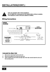
Do not attach the control panel to the chassis before wiring is 200mA. Remove the plastic trim out from the main unit. 2. Gray + Front Right Speaker Gray/Black - Green + Rear Left Speaker Green/Black - The maximum ... metal strap from the main unit. 3. White + Front Left Speaker White/Black - ACC + (Red) GND - (Black) ANT + (Blue) Power B + (Yellow) Uninstall the Main Unit 1. Wiring Connections WIRING DIAGRAM 15A 15 Radio Antenna White:Front Left PRE-AMP Output Red: Front Right PRE-AMP Output Red: Rear Right PRE-AMP Output White: Rear Left...
Do not attach the control panel to the chassis before wiring is 200mA. Remove the plastic trim out from the main unit. 2. Gray + Front Right Speaker Gray/Black - Green + Rear Left Speaker Green/Black - The maximum ... metal strap from the main unit. 3. White + Front Left Speaker White/Black - ACC + (Red) GND - (Black) ANT + (Blue) Power B + (Yellow) Uninstall the Main Unit 1. Wiring Connections WIRING DIAGRAM 15A 15 Radio Antenna White:Front Left PRE-AMP Output Red: Front Right PRE-AMP Output Red: Rear Right PRE-AMP Output White: Rear Left...


