Installation guide
Page 17
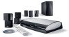
...below show basic connections to the media center and TV. Note: It is connected to the VIDEO 1 input on the rear panel of the digital signal. If the setup menu for fixed output. Making the audio ... center Video OUT is important to provide the analog connection along with RCA connectors on each end, or an optical cable, which Video IN jack is used. It may have a digital TV, you may either be sure ... any temporary degradation of your system quickly. English System Installation Connecting your LIFESTYLE® system This video connection allows you to view DVDs and see...
...below show basic connections to the media center and TV. Note: It is connected to the VIDEO 1 input on the rear panel of the digital signal. If the setup menu for fixed output. Making the audio ... center Video OUT is important to provide the analog connection along with RCA connectors on each end, or an optical cable, which Video IN jack is used. It may have a digital TV, you may either be sure ... any temporary degradation of your system quickly. English System Installation Connecting your LIFESTYLE® system This video connection allows you to view DVDs and see...
Installation guide
Page 24
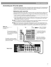
...your media center. The remaining video connections go from the Composite Video OUT on the media center and to the S-Video input on your local electronics store or authorized Bose® dealer. The adapter uses both Video out jacks on the media center, so you can be made from components... Note: You need to the Y, Pb, and Pr jacks on the following pages show variations that came with RCA connectors at each end), or an optical connection. See "Using digital audio connections" on page 30. • A composite and an S-Video connection or a single component connection can only make ...
...your media center. The remaining video connections go from the Composite Video OUT on the media center and to the S-Video input on your local electronics store or authorized Bose® dealer. The adapter uses both Video out jacks on the media center, so you can be made from components... Note: You need to the Y, Pb, and Pr jacks on the following pages show variations that came with RCA connectors at each end), or an optical connection. See "Using digital audio connections" on page 30. • A composite and an S-Video connection or a single component connection can only make ...

Installation guide
Page 29
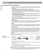
.../playback equipment The rear panel of the media center provides input (AUX) jacks for listening to and output (Audio OUT) jacks for recording to the media center. You must identify the optical source using the System/Media Center/Optical Source menu. If the component is mono, use a ...listening to tape Record/playback component Connecting other unused inputs on the rear panel of the media center. 29 Appropriate cables and adapters are available at most electronic stores. If the component has a digital output use an optical connection, if the component has one. English Reference...
.../playback equipment The rear panel of the media center provides input (AUX) jacks for listening to and output (Audio OUT) jacks for recording to the media center. You must identify the optical source using the System/Media Center/Optical Source menu. If the component is mono, use a ...listening to tape Record/playback component Connecting other unused inputs on the rear panel of the media center. 29 Appropriate cables and adapters are available at most electronic stores. If the component has a digital output use an optical connection, if the component has one. English Reference...
Installation guide
Page 30
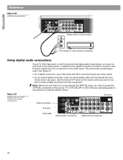
Note: Before you can listen to a source through the OPTICAL input, you need to assign the OPTICAL connection to the media center. Figure 27 Digital audio and other playback equipment Using digital audio connections If your operating guide for instructions ... to make a digital recording from the component to that component. English Reference Figure 26 AUX input connections Media center connector panel AUDIO OUT R L CD changer or other media center panel connections. Use the Optical OUT jacks on the media center rear panel. Antenna extender Data port IR emitter Serial data...
Note: Before you can listen to a source through the OPTICAL input, you need to assign the OPTICAL connection to the media center. Figure 27 Digital audio and other playback equipment Using digital audio connections If your operating guide for instructions ... to make a digital recording from the component to that component. English Reference Figure 26 AUX input connections Media center connector panel AUDIO OUT R L CD changer or other media center panel connections. Use the Optical OUT jacks on the media center rear panel. Antenna extender Data port IR emitter Serial data...
Installation guide
Page 34
... TV Sensor: Scan frequency sensing Media center outputs Speakers Main and Expansion: Variable audio, user selectable Optical OUT: • SPDIF, -15 to -21 dbm Audio OUT: • L and R ...sure to fill out the information section on speaker mounting brackets and stands, additional remote controls, and connecting additional Bose® powered loudspeakers, contact your system. L, R and D (digital SPDIF) • VCR: 2Vrms,... 50/60 Hz 350W Media center inputs Audio IN: • AUX: 2Vrms, maximum; Limited warranty Your LIFESTYLE® home entertainment system is covered...
... TV Sensor: Scan frequency sensing Media center outputs Speakers Main and Expansion: Variable audio, user selectable Optical OUT: • SPDIF, -15 to -21 dbm Audio OUT: • L and R ...sure to fill out the information section on speaker mounting brackets and stands, additional remote controls, and connecting additional Bose® powered loudspeakers, contact your system. L, R and D (digital SPDIF) • VCR: 2Vrms,... 50/60 Hz 350W Media center inputs Audio IN: • AUX: 2Vrms, maximum; Limited warranty Your LIFESTYLE® home entertainment system is covered...
Operating guide
Page 57
... sync on Y OPTICAL INPUT: SPDIF digital, mapped to input FM antenna: 75 Ω AM antenna: 12µH TV SENSOR: Scan frequency sensing Media center outputs SPEAKER ZONES 1 and 2: Variable audio, user selectable AUDIO OUT: L and R: Fixed audio, 2 Vrms maximum DIGITAL AUDIO OUT: SPDIF OPTICAL OUTPUT: SPDIF, -15 to Bose. Limited warranty Your LIFESTYLE® home theater...
... sync on Y OPTICAL INPUT: SPDIF digital, mapped to input FM antenna: 75 Ω AM antenna: 12µH TV SENSOR: Scan frequency sensing Media center outputs SPEAKER ZONES 1 and 2: Variable audio, user selectable AUDIO OUT: L and R: Fixed audio, 2 Vrms maximum DIGITAL AUDIO OUT: SPDIF OPTICAL OUTPUT: SPDIF, -15 to Bose. Limited warranty Your LIFESTYLE® home theater...


