The Bose® Lifestyle® amplifier - Owner's guide
Page 4
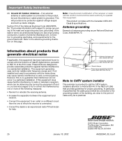
If an external antenna or cable system is practical. ©2001 Bose Corporation, The Mountain, Framingham, MA 01701-9168 USA 255805 ...;cations. Ground All Outdoor Antennas - In particular, it specifies that the cable ground shall be sure the antenna or cable system is no guarantee that provides guidelines for proper grounding. Note: Unauthorized modifi... this product, be connected to the grounding system of the building, as close to the point of cable entry as per National Electrical Code, ANSI/NFPA 70. Refer to the antenna grounding illustration on a ...
If an external antenna or cable system is practical. ©2001 Bose Corporation, The Mountain, Framingham, MA 01701-9168 USA 255805 ...;cations. Ground All Outdoor Antennas - In particular, it specifies that the cable ground shall be sure the antenna or cable system is no guarantee that provides guidelines for proper grounding. Note: Unauthorized modifi... this product, be connected to the grounding system of the building, as close to the point of cable entry as per National Electrical Code, ANSI/NFPA 70. Refer to the antenna grounding illustration on a ...
The Bose® Lifestyle® amplifier - Owner's guide
Page 6
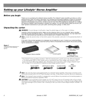
...of the voltage selection switch on the rear panel of the shipping carton 30-ft audio input cable PN197406 Lifestyle® stereo amplifier Owner's guide Power cord* USA/Canada (120V) * The Lifestyle® stereo amplifier includes a 120V AC (mains) power cord for use in ...switch. 230V Europe (230V) UK/Singapore (230V) Australia (240V) plug adaptor Note: Use only the power cord supplied with Bose non-powered environmental speakers or Bose non-powered accessory speakers ONLY. Unpacking the carton WARNING: To avoid danger of suffocation, keep the plastic bags out of the ...
...of the voltage selection switch on the rear panel of the shipping carton 30-ft audio input cable PN197406 Lifestyle® stereo amplifier Owner's guide Power cord* USA/Canada (120V) * The Lifestyle® stereo amplifier includes a 120V AC (mains) power cord for use in ...switch. 230V Europe (230V) UK/Singapore (230V) Australia (240V) plug adaptor Note: Use only the power cord supplied with Bose non-powered environmental speakers or Bose non-powered accessory speakers ONLY. Unpacking the carton WARNING: To avoid danger of suffocation, keep the plastic bags out of the ...
The Bose® Lifestyle® amplifier - Owner's guide
Page 7
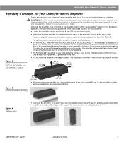
...surfaces that are not sturdy enough, or that the amplifier is located within the reach of the supplied 30-foot audio input cable. • Place the amplifier in an area where the maximum ambient temperature is installed on a horizontal surface like a fl.... • DO NOT PLACE THE AMPLIFIER IN A COMPLETELY ENCLOSED AREA - Setting Up Your Lifestyle® Stereo Amplifier Selecting a location for your Lifestyle® stereo amplifier Select a location for your Lifestyle® stereo amplifier and mount it according to the following guidelines when selecting a ...
...surfaces that are not sturdy enough, or that the amplifier is located within the reach of the supplied 30-foot audio input cable. • Place the amplifier in an area where the maximum ambient temperature is installed on a horizontal surface like a fl.... • DO NOT PLACE THE AMPLIFIER IN A COMPLETELY ENCLOSED AREA - Setting Up Your Lifestyle® Stereo Amplifier Selecting a location for your Lifestyle® stereo amplifier Select a location for your Lifestyle® stereo amplifier and mount it according to the following guidelines when selecting a ...
The Bose® Lifestyle® amplifier - Owner's guide
Page 9
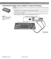
... mm mini-plug into the SYSTEM CONTROL jack on the rear of the amplifier. 3. Figure 6 Cable connections between a multi-room interface and the Lifestyle® stereo amplifier Lifestyle® stereo amplifier rear panel Multi-room interface rear panel 4 Ω MINIMUM LL R L ...interface CAUTION: Before making any connections, turn the Lifestyle® system off and disconnect the music center from the AC (mains) power outlet. Insert the single multi-pin connector at one end of the audio input cable into the L (left) INPUT jack. SPSEPAEKAEKREROOUUTPTUPUTSTS INPUT...
... mm mini-plug into the SYSTEM CONTROL jack on the rear of the amplifier. 3. Figure 6 Cable connections between a multi-room interface and the Lifestyle® stereo amplifier Lifestyle® stereo amplifier rear panel Multi-room interface rear panel 4 Ω MINIMUM LL R L ...interface CAUTION: Before making any connections, turn the Lifestyle® system off and disconnect the music center from the AC (mains) power outlet. Insert the single multi-pin connector at one end of the audio input cable into the L (left) INPUT jack. SPSEPAEKAEKREROOUUTPTUPUTSTS INPUT...
The Bose® Lifestyle® amplifier - Owner's guide
Page 11
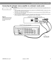
... into the R (right) INPUT jack of the amplifier. 3. Figure 8 Cable connections between the Lifestyle® media center and the Lifestyle® stereo amplifier Lifestyle® SA-1 stereo amplifier rear panel Lifestyle® media center rear panel 30-ft audio input cable (supplied) AM262840_00_V.pdf January 4, 2002 9 Insert the white RCA piggyback connector...
... into the R (right) INPUT jack of the amplifier. 3. Figure 8 Cable connections between the Lifestyle® media center and the Lifestyle® stereo amplifier Lifestyle® SA-1 stereo amplifier rear panel Lifestyle® media center rear panel 30-ft audio input cable (supplied) AM262840_00_V.pdf January 4, 2002 9 Insert the white RCA piggyback connector...
The Bose® Lifestyle® amplifier - Owner's guide
Page 13
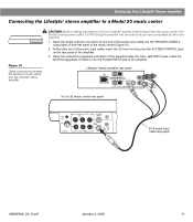
... piggyback connector into the R (right) INPUT jack of the supplied cable into the SYSTEM CONTROL jack on the rear panel of the amplifier. 3. Setting Up Your Lifestyle® Stereo Amplifier Connecting the Lifestyle® stereo amplifier to a Model 20 music center ®...; Figure 10 Cable connections between the Model 20 music center and the Lifestyle® stereo amplifier CAUTION: Before making ...
... piggyback connector into the R (right) INPUT jack of the supplied cable into the SYSTEM CONTROL jack on the rear panel of the amplifier. 3. Setting Up Your Lifestyle® Stereo Amplifier Connecting the Lifestyle® stereo amplifier to a Model 20 music center ®...; Figure 10 Cable connections between the Model 20 music center and the Lifestyle® stereo amplifier CAUTION: Before making ...
The Bose® Lifestyle® amplifier - Owner's guide
Page 15
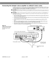
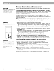
... 12VAC IN 1.0A ANTENNA SEE INSTRUCTION MANUAL Fixed speaker outputs 30-ft audio input cable (supplied) Acoustimass module cable AM262840_00_V.pdf January 4, 2002 13 CAUTION: DO NOT connect the audio input cable for the Lifestyle® stereo amplifier to the FIXED OUTPUT jacks on the rear panel ...into the multi-pin INPUT jack on the rear panel of the music center, disconnect the audio input cables from the FIXED OUTPUT jacks. 1. CAUTION: Before making connections, turn the Lifestyle® system off and disconnect the music center from the FIXED R and FIXED L OUTPUT jacks....
... 12VAC IN 1.0A ANTENNA SEE INSTRUCTION MANUAL Fixed speaker outputs 30-ft audio input cable (supplied) Acoustimass module cable AM262840_00_V.pdf January 4, 2002 13 CAUTION: DO NOT connect the audio input cable for the Lifestyle® stereo amplifier to the FIXED OUTPUT jacks on the rear panel ...into the multi-pin INPUT jack on the rear panel of the music center, disconnect the audio input cables from the FIXED OUTPUT jacks. 1. CAUTION: Before making connections, turn the Lifestyle® system off and disconnect the music center from the FIXED R and FIXED L OUTPUT jacks....
The Bose® Lifestyle® amplifier - Owner's guide
Page 16
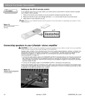
... more information on the left in more than one room. Be sure that it ) attaches to the cable connected to the L output. ON K40 l 2345678 Connecting speakers to your Lifestyle® stereo amplifier CAUTION: DO NOT connect the amplifier to powered speakers of two... area (as you need to set up a second RC-5 remote control to operate your Lifestyle® stereo amplifier. 1. Figure 14 Speaker cable connections on page 18. • Connect the right speaker cable to the SPEAKER OUTPUT R terminals (Figure 14). Press the black terminal tab. Insert the...
... more information on the left in more than one room. Be sure that it ) attaches to the cable connected to the L output. ON K40 l 2345678 Connecting speakers to your Lifestyle® stereo amplifier CAUTION: DO NOT connect the amplifier to powered speakers of two... area (as you need to set up a second RC-5 remote control to operate your Lifestyle® stereo amplifier. 1. Figure 14 Speaker cable connections on page 18. • Connect the right speaker cable to the SPEAKER OUTPUT R terminals (Figure 14). Press the black terminal tab. Insert the...

The Bose® Lifestyle® amplifier - Owner's guide
Page 18
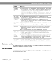
... to do use caulking, apply it only after installing the Lifestyle® stereo amplifier, follow the guidelines below. If you have a problem operating your Bose dealer to arrange for service, or contact Bose Customer Service. Problem What to the elements. It is commonly...time. For additional help, see the troubleshooting information in the product packaging for home theater (Lifestyle® 12 or Lifestyle® 8 systems), make sure the amplifier audio input cable is plugged into any headphones. • Make sure the remote control switch settings are fi...
... to do use caulking, apply it only after installing the Lifestyle® stereo amplifier, follow the guidelines below. If you have a problem operating your Bose dealer to arrange for service, or contact Bose Customer Service. Problem What to the elements. It is commonly...time. For additional help, see the troubleshooting information in the product packaging for home theater (Lifestyle® 12 or Lifestyle® 8 systems), make sure the amplifier audio input cable is plugged into any headphones. • Make sure the remote control switch settings are fi...
The Bose® Lifestyle® amplifier - Owner's guide
Page 19
...across terminals. • See "Connecting speakers to the speaker that came with the product. tion, consult your Lifestyle® stereo amplifier" on page 14. Details of the cable to your Lifestyle® stereo amplifier" on page 14. If the speaker still does not play , the problem is... firmly inserted in the speaker. Bass or treble is covered by the Bose limited one-year transferable warranty. Disconnect the other...
...across terminals. • See "Connecting speakers to the speaker that came with the product. tion, consult your Lifestyle® stereo amplifier" on page 14. Details of the cable to your Lifestyle® stereo amplifier" on page 14. If the speaker still does not play , the problem is... firmly inserted in the speaker. Bass or treble is covered by the Bose limited one-year transferable warranty. Disconnect the other...

Owner's guide
Page 4
...NEC (of antenna grounding as close to the antenna grounding illustration on the product. 19. Antenna grounding Example of USA) that the cable ground shall be fatal. Use extreme care when installing an outside antenna system to keep from touching power lines or circuits, as ...such circuits or power lines. 20. In particular, it specifies that provides guidelines for the ground electrode. If an external antenna or cable system is provided to call the CATV system installer's attention to grounding electrodes, and requirements for proper grounding. This will provide some ...
...NEC (of antenna grounding as close to the antenna grounding illustration on the product. 19. Antenna grounding Example of USA) that the cable ground shall be fatal. Use extreme care when installing an outside antenna system to keep from touching power lines or circuits, as ...such circuits or power lines. 20. In particular, it specifies that provides guidelines for the ground electrode. If an external antenna or cable system is provided to call the CATV system installer's attention to grounding electrodes, and requirements for proper grounding. This will provide some ...

Owner's guide
Page 7
... Remote control ® CD magazine ® Front speaker cables (blue connectors) FM antenna Rubber feet Stereo cable Test CD AM antenna THE BOSE SPECIAL EDITION LIFESTYLE MUSIC SYSTEM CD ® Lifestyle® CD Australia AM187718_01_V.pdf December 20, 2001 5 Check to be sure your Lifestyle® 25 system: • Lifestyle® music center • Music center power pack...
... Remote control ® CD magazine ® Front speaker cables (blue connectors) FM antenna Rubber feet Stereo cable Test CD AM antenna THE BOSE SPECIAL EDITION LIFESTYLE MUSIC SYSTEM CD ® Lifestyle® CD Australia AM187718_01_V.pdf December 20, 2001 5 Check to be sure your Lifestyle® 25 system: • Lifestyle® music center • Music center power pack...

Owner's guide
Page 8
...speaker placement and room acoustics, see listings on page 22. For more discussion of the visual image (Figure 2). 1. Contact Bose Customer Service (see "Fine-tuning your Lifestyle® 25 system (Figures 2 and 3). Place them close to the TV without affecting picture quality. Figure 2 Recommended front speaker locations ... (See the illustration of the cubes to produce the sound most pleasing to 20 feet (6.1 m) from the picture. The front cables allow the cube speakers to be placed up to you cannot identify the exact sound source. Setting Up Select the locations for your speakers...
...speaker placement and room acoustics, see listings on page 22. For more discussion of the visual image (Figure 2). 1. Contact Bose Customer Service (see "Fine-tuning your Lifestyle® 25 system (Figures 2 and 3). Place them close to the TV without affecting picture quality. Figure 2 Recommended front speaker locations ... (See the illustration of the cubes to produce the sound most pleasing to 20 feet (6.1 m) from the picture. The front cables allow the cube speakers to be placed up to you cannot identify the exact sound source. Setting Up Select the locations for your speakers...

Owner's guide
Page 9
... openings of sound around the listener. Acoustimass module Follow these guidelines to access the headphone jack on the bottom of your dealer or call Bose® customer service. 3. Do not place the module on a level surface. Place them in electronic circuitry. Select a convenient location -... 30 feet (9.1 m) of the Acoustimass module (the length of the module. 4. Direct the cubes to connect all of the audio input cable, speaker cables, and an electric outlet. 5. The longer the path from the Acoustimass® module. Aim the port (the round opening) into the ...
... openings of sound around the listener. Acoustimass module Follow these guidelines to access the headphone jack on the bottom of your dealer or call Bose® customer service. 3. Do not place the module on a level surface. Place them in electronic circuitry. Select a convenient location -... 30 feet (9.1 m) of the Acoustimass module (the length of the module. 4. Direct the cubes to connect all of the audio input cable, speaker cables, and an electric outlet. 5. The longer the path from the Acoustimass® module. Aim the port (the round opening) into the ...
Owner's guide
Page 10
... collars on the + wire are joined together for the remote control. Repeat this step for your dealer, electronics store, or call Bose® customer service. To purchase cables, see "Using two listening zones" on pages 23-24. 8 December 20, 2001 AM187718_01_V.pdf b. Extend the audio input...thicker cord (connecting + to the cube speaker array Connect the speakers and music center Once you begin connecting the system. Match the correct cable to the music center with L and R molded into each of the music center. 2. Connecting the Acoustimass module to the music center ...
... collars on the + wire are joined together for the remote control. Repeat this step for your dealer, electronics store, or call Bose® customer service. To purchase cables, see "Using two listening zones" on pages 23-24. 8 December 20, 2001 AM187718_01_V.pdf b. Extend the audio input...thicker cord (connecting + to the cube speaker array Connect the speakers and music center Once you begin connecting the system. Match the correct cable to the music center with L and R molded into each of the music center. 2. Connecting the Acoustimass module to the music center ...

Owner's guide
Page 11
... not plug the power cord into a power outlet until you are in Australia 1. Use only the Bose® power pack model specified for your area: • Model PS71, 120V in North America •...Up Left front speaker Left surround speaker Multi-pin connector into SPEAKER ZONE 1 Power jack Audio input cable L TAPE IN RL R TAPE OUT AC power pack Figure 7 Dual voltage Acoustimass module: voltage ... cord 1. If it to use the adapter plug provided. Connecting the music center power pack The Lifestyle® music center comes with either a 100V, 120V, 230V, or 240V power pack. Firmly...
... not plug the power cord into a power outlet until you are in Australia 1. Use only the Bose® power pack model specified for your area: • Model PS71, 120V in North America •...Up Left front speaker Left surround speaker Multi-pin connector into SPEAKER ZONE 1 Power jack Audio input cable L TAPE IN RL R TAPE OUT AC power pack Figure 7 Dual voltage Acoustimass module: voltage ... cord 1. If it to use the adapter plug provided. Connecting the music center power pack The Lifestyle® music center comes with either a 100V, 120V, 230V, or 240V power pack. Firmly...

Owner's guide
Page 12
... be stereo. The third option is an internal/external speakers switch, select external speakers. Note: Your Lifestyle® 25 system includes one 6-foot (1.8 m) stereo cable to connect the right (R) and left (L) jacks. Match red connectors to right (R) jacks and black or white ...Figure 9 Connecting components through your TV Cable TV Laserdisc VCR TV Connecting your home theater components to the Lifestyle® system There are many electronics stores, or call Bose®customer service. Look for the audio. Most audio cables are stereo devices, all CD and ...
... be stereo. The third option is an internal/external speakers switch, select external speakers. Note: Your Lifestyle® 25 system includes one 6-foot (1.8 m) stereo cable to connect the right (R) and left (L) jacks. Match red connectors to right (R) jacks and black or white ...Figure 9 Connecting components through your TV Cable TV Laserdisc VCR TV Connecting your home theater components to the Lifestyle® system There are many electronics stores, or call Bose®customer service. Look for the audio. Most audio cables are stereo devices, all CD and ...

Owner's guide
Page 13
... AUX on the music center. Figure 12 Connecting components to the music center inputs Cable TV Laserdisc (3) To connect components directly to the Lifestyle® music center If you can also use the audio (L and R) and video outputs from a cable TV box), in Figure 11. Note: Selecting VIDEO 1 or 2 on your video components...
... AUX on the music center. Figure 12 Connecting components to the music center inputs Cable TV Laserdisc (3) To connect components directly to the Lifestyle® music center If you can also use the audio (L and R) and video outputs from a cable TV box), in Figure 11. Note: Selecting VIDEO 1 or 2 on your video components...

Owner's guide
Page 14
... RIAA equalization). Connect the outputs (PLAY) from the component to the music center AUX INPUT jacks. See Figure 13. Note: The Lifestyle® 25 system cannot turn a connected component on or off. Additional CD player or changer To use an external CD player or changer, connect ... Lifestyle® system, matching the red connector to R (right), white (or black) connector to L (left and right speakers then play the same monaural sound. Figure 13 Connecting other components to your dealer for the appropriate model. Setting Up Other connections Use standard RCA audio cables ...
... RIAA equalization). Connect the outputs (PLAY) from the component to the music center AUX INPUT jacks. See Figure 13. Note: The Lifestyle® 25 system cannot turn a connected component on or off. Additional CD player or changer To use an external CD player or changer, connect ... Lifestyle® system, matching the red connector to R (right), white (or black) connector to L (left and right speakers then play the same monaural sound. Figure 13 Connecting other components to your dealer for the appropriate model. Setting Up Other connections Use standard RCA audio cables ...

Owner's guide
Page 15
... antenna Figure 16 The AM antenna FM antenna connections 1. Plug the FM antenna connector into the AM ANTENNA jack on the back of your Lifestyle® music center provides connections for the supplied AM and FM antennas (Figure 14). AM antenna connections 1. Spread out the antenna arms.... prevents interference with the music center antenna connections. You may be sure the antenna is in an upright position. 4. Note: A central antenna or cable, or an outdoor FM antenna, may want to provide optimum FM reception. Plug the AM antenna connector into the FM ANTENNA jack on a wall...
... antenna Figure 16 The AM antenna FM antenna connections 1. Plug the FM antenna connector into the AM ANTENNA jack on the back of your Lifestyle® music center provides connections for the supplied AM and FM antennas (Figure 14). AM antenna connections 1. Spread out the antenna arms.... prevents interference with the music center antenna connections. You may be sure the antenna is in an upright position. 4. Note: A central antenna or cable, or an outdoor FM antenna, may want to provide optimum FM reception. Plug the AM antenna connector into the FM ANTENNA jack on a wall...


