Owners Manual
Page 2
... all of fire or electric shock, do not expose the system to the presence of the Canadian Interference-Causing Equipment Regulations. Save your 3•2•1 Series II home entertainment system media center and the rear panel of the Acoustimass module: The lightning flash with liquids, such as lighted candles, should not...
... all of fire or electric shock, do not expose the system to the presence of the Canadian Interference-Causing Equipment Regulations. Save your 3•2•1 Series II home entertainment system media center and the rear panel of the Acoustimass module: The lightning flash with liquids, such as lighted candles, should not...
Owners Manual
Page 3
... discs 5 Check for region code compatibility 5 MP3 compatibility 5 Glossary of terms 6 Limited warranty 7 For your records 7 System Setup 8 Unpacking 8 Selecting locations for your 3•2•1 Series II system components 9 Placing the media center 9 Placing the speakers 10 Placing the Acoustimass® module 11 Making system connections 12 Connecting the Acoustimass module...
... discs 5 Check for region code compatibility 5 MP3 compatibility 5 Glossary of terms 6 Limited warranty 7 For your records 7 System Setup 8 Unpacking 8 Selecting locations for your 3•2•1 Series II system components 9 Placing the media center 9 Placing the speakers 10 Placing the Acoustimass® module 11 Making system connections 12 Connecting the Acoustimass module...
Owners Manual
Page 5
... effort to set up, so you for purchasing the Bose® 3•2•1 Series II or 3•2•1 GS Series II DVD home entertainment system, which must also match the DVD discs. Check the region code number on the carton of the 3•2•1 Series II DVD home entertainment system or on the disc label...
... effort to set up, so you for purchasing the Bose® 3•2•1 Series II or 3•2•1 GS Series II DVD home entertainment system, which must also match the DVD discs. Check the region code number on the carton of the 3•2•1 Series II DVD home entertainment system or on the disc label...

Owners Manual
Page 7
...center and the rear of the limited warranty are covered by a limited transferable warranty. Failure to Bose. Model: 3•2•1 Series II 3•2•1 GS Series II Check one Media center serial number Acoustimass module serial number Dealer name Dealer phone Purchase date...more than composite video since it to do so will not affect your system. Limited warranty The 3•2•1 Series II and 3•2•1 GS Series II home entertainment systems are provided on the product registration card that came with this owner's guide. 7 Introduction ...
...center and the rear of the limited warranty are covered by a limited transferable warranty. Failure to Bose. Model: 3•2•1 Series II 3•2•1 GS Series II Check one Media center serial number Acoustimass module serial number Dealer name Dealer phone Purchase date...more than composite video since it to do so will not affect your system. Limited warranty The 3•2•1 Series II and 3•2•1 GS Series II home entertainment systems are provided on the product registration card that came with this owner's guide. 7 Introduction ...
Owners Manual
Page 8
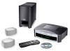
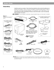
... center Acoustimass® module cable 3•2•1 speakers or Acoustimass module Speaker cable Note: If you purchased a 3•2•1 GS Series II system, the left and right speaker cable connectors will be sure your system includes the parts shown in the carton. Check to...Europe) 230 VAC power cord (UK/Singapore) Carefully unpack your system. For Bose contact information, refer to find the serial numbers on page 7. 8 Rubber feet for Acoustimass module 3•2•1 GS speakers Rubber feet for speakers Remote control Batteries Stereo cable Video cable 240 VAC ...
... center Acoustimass® module cable 3•2•1 speakers or Acoustimass module Speaker cable Note: If you purchased a 3•2•1 GS Series II system, the left and right speaker cable connectors will be sure your system includes the parts shown in the carton. Check to...Europe) 230 VAC power cord (UK/Singapore) Carefully unpack your system. For Bose contact information, refer to find the serial numbers on page 7. 8 Rubber feet for Acoustimass module 3•2•1 GS speakers Rubber feet for speakers Remote control Batteries Stereo cable Video cable 240 VAC ...
Owners Manual
Page 9
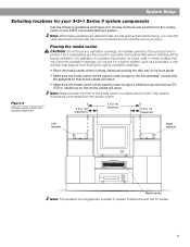
... magnetically shielded to choose locations and positions for your 3•2•1 home entertainment system. System Setup Selecting locations for the components of your 3•2•1 Series II system components Use the following guidelines and Figure 2 to prevent interference with its proper ventilation.
... magnetically shielded to choose locations and positions for your 3•2•1 home entertainment system. System Setup Selecting locations for the components of your 3•2•1 Series II system components Use the following guidelines and Figure 2 to prevent interference with its proper ventilation.

Owners Manual
Page 13
Plug the LEFT speaker cable into the rear jack on the right speaker. Note: If you purchased a 3•2•1 GS Series II system, the left and right speaker cords as much as necessary to reach each speaker (Figure 8). Figure 9 Left and right speaker connections 3. ... Plug the RIGHT speaker cable into the rear jack of the speaker cable, separate the left and right speaker cable connectors will be marked with a "GS". Figure 8 Separating left speaker (Figure 9). RIGHT RIGHT speaker cable LEFT LEFT speaker cable Note: Make sure cable connectors are fully inserted and seated firmly...
Plug the LEFT speaker cable into the rear jack on the right speaker. Note: If you purchased a 3•2•1 GS Series II system, the left and right speaker cords as much as necessary to reach each speaker (Figure 8). Figure 9 Left and right speaker connections 3. ... Plug the RIGHT speaker cable into the rear jack of the speaker cable, separate the left and right speaker cable connectors will be marked with a "GS". Figure 8 Separating left speaker (Figure 9). RIGHT RIGHT speaker cable LEFT LEFT speaker cable Note: Make sure cable connectors are fully inserted and seated firmly...

Owners Manual
Page 18
...Making S-video connections (higher quality video) An S-video input jack, provided on your TV. For this setup, you will hear mono sound from your Bose dealer or a local electronics retailer. • Insert one audio output and is required for information. • A stereo VCR is not labeled Stereo...Hi-fi, you have a mono VCR. System Setup VCR considerations • Some combination TV/VCR units may not work with 3•2•1 Series II home entertainment systems. Please refer to your TV/VCR owner's manual for optimal sound performance. For this connection you will need an S-video...
...Making S-video connections (higher quality video) An S-video input jack, provided on your TV. For this setup, you will hear mono sound from your Bose dealer or a local electronics retailer. • Insert one audio output and is required for information. • A stereo VCR is not labeled Stereo...Hi-fi, you have a mono VCR. System Setup VCR considerations • Some combination TV/VCR units may not work with 3•2•1 Series II home entertainment systems. Please refer to your TV/VCR owner's manual for optimal sound performance. For this connection you will need an S-video...

Owners Manual
Page 20
... TV also through an S-video connection. • Analog and digital coax audio connections are used to deliver the cable/satellite signal to the 3•2•1 Series II system. Note: The digital audio inputs of the 3•2•1 system are basic suggestions for these external devices may vary, depending on making any...
... TV also through an S-video connection. • Analog and digital coax audio connections are used to deliver the cable/satellite signal to the 3•2•1 Series II system. Note: The digital audio inputs of the 3•2•1 system are basic suggestions for these external devices may vary, depending on making any...
Owners Manual
Page 21
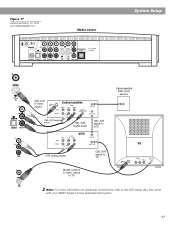
Figure 17 Advanced setup: TV, VCR and cable/satellite box Media center System Setup CBL-SAT S-video output Cable/satellite Cable/satellite (CBL-SAT) service CBL-SAT analog audio CBL-SAT digital audio VCR CBL-SAT signal to VCR TV VCR analog audio CBL-SAT signal to TV Media center's S-video output to TV Note: For more information on advanced connections, refer to the DVD setup disc that came with your 3•2•1 Series II home entertainment system. 21
Figure 17 Advanced setup: TV, VCR and cable/satellite box Media center System Setup CBL-SAT S-video output Cable/satellite Cable/satellite (CBL-SAT) service CBL-SAT analog audio CBL-SAT digital audio VCR CBL-SAT signal to VCR TV VCR analog audio CBL-SAT signal to TV Media center's S-video output to TV Note: For more information on advanced connections, refer to the DVD setup disc that came with your 3•2•1 Series II home entertainment system. 21
Owners Manual
Page 34
Use the 3•2•1 Series II or 3•2•1 GS Series II system remote to get started: • Pressing TV, CBL-SAT, or AUX on the 3•2•1 or 3•2•1 GS system remote turns on the media center to raise or lower the volume of listening to the media center by using the remote...
Use the 3•2•1 Series II or 3•2•1 GS Series II system remote to get started: • Pressing TV, CBL-SAT, or AUX on the 3•2•1 or 3•2•1 GS system remote turns on the media center to raise or lower the volume of listening to the media center by using the remote...

Owners Manual
Page 48
...navigate select System Option Display Brightness Display Language Optical Source Tuner Spacing Bose link Room Code* Restore Factory Defaults Settings Description 4 [default] 1 (darkest) to factory defaults. ** Appears only when a Bose® link source is connected to selected region standard. Yes ... received via optical cable for AM/FM radio stations set to a Bose® link source. Darkens or lightens the media center display. B [default], C, D, E, F, G, H, I, J, K, Assigns a room code to your 3•2•1 Series II system when L, M, N, or O it is connected. 48...
...navigate select System Option Display Brightness Display Language Optical Source Tuner Spacing Bose link Room Code* Restore Factory Defaults Settings Description 4 [default] 1 (darkest) to factory defaults. ** Appears only when a Bose® link source is connected to selected region standard. Yes ... received via optical cable for AM/FM radio stations set to a Bose® link source. Darkens or lightens the media center display. B [default], C, D, E, F, G, H, I, J, K, Assigns a room code to your 3•2•1 Series II system when L, M, N, or O it is connected. 48...
Owners Manual
Page 53
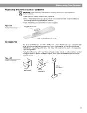
... for use in the batteries AA batteries (IEC R6) Accessories Figure 35 Speaker accessories Battery compartment cover The Bose® 3•2•1 Series II and 3•2•1 GS Series II system shelf speakers are compatible with Bose mounting accessories, including the UB-20 wall brackets, UFS-20 floor stands and UTS-20 table stands (Figure...
... for use in the batteries AA batteries (IEC R6) Accessories Figure 35 Speaker accessories Battery compartment cover The Bose® 3•2•1 Series II and 3•2•1 GS Series II system shelf speakers are compatible with Bose mounting accessories, including the UB-20 wall brackets, UFS-20 floor stands and UTS-20 table stands (Figure...


