Installation Instructions
Page 3
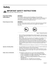
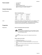
... devices are a maximum of 13" (330 mm) deep. • Do not lift appliance by a qualified technician. WARNING: All ranges can cause injury or property damage. Never allow children to play with range. See instructions in the manuals. Improper installation, service or maintenance can tip. Destroy the... • UL 858, The Standard for the Safety of Household Electric Ranges • UL 923, The Standard for the Safety of Microwave Cooking Appliances • UL 507, The Standard for the Safety of the appliance unless specifically recommended in Use and Care Manual. • Unit is to...
... devices are a maximum of 13" (330 mm) deep. • Do not lift appliance by a qualified technician. WARNING: All ranges can cause injury or property damage. Never allow children to play with range. See instructions in the manuals. Improper installation, service or maintenance can tip. Destroy the... • UL 858, The Standard for the Safety of Household Electric Ranges • UL 923, The Standard for the Safety of Microwave Cooking Appliances • UL 507, The Standard for the Safety of the appliance unless specifically recommended in Use and Care Manual. • Unit is to...
Installation Instructions
Page 4
... is any doubt as to whether the wall receptacle is properly grounded, the customer should have it for the local electrical inspector's use with ranges" shall be used. • Installer - Safety Electric Safety Gas Safety It is the responsibility of the owner and the installer to determine... installations. • Installation must conform with local codes or, in the absence of local codes, with the National Fuel Gas Code, ANSI Z223.1/NFPA 54. • The appliance must be electrically grounded in accordance with local codes or, in the absence of local codes, with the National Electrical...
... is any doubt as to whether the wall receptacle is properly grounded, the customer should have it for the local electrical inspector's use with ranges" shall be used. • Installer - Safety Electric Safety Gas Safety It is the responsibility of the owner and the installer to determine... installations. • Installation must conform with local codes or, in the absence of local codes, with the National Fuel Gas Code, ANSI Z223.1/NFPA 54. • The appliance must be electrically grounded in accordance with local codes or, in the absence of local codes, with the National Electrical...
Installation Instructions
Page 5
...licensed contractor, plumber or gas fitter qualified or licensed by the state, province or region where this unit must also be used. • The appliance is located. • The propane gas tank must be longer than 36 inches. • Installer - It must be performed by a qualified ... column (34.9Millibars). Follow the gas supplier's instructions. • If you cannot reach your gas supplier from the factory for use with this appliance is not followed exactly, a fire or explosion may result causing property damage, personal injury or death. • Do not store or use combustible...
...licensed contractor, plumber or gas fitter qualified or licensed by the state, province or region where this unit must also be used. • The appliance is located. • The propane gas tank must be longer than 36 inches. • Installer - It must be performed by a qualified ... column (34.9Millibars). Follow the gas supplier's instructions. • If you cannot reach your gas supplier from the factory for use with this appliance is not followed exactly, a fire or explosion may result causing property damage, personal injury or death. • Do not store or use combustible...
Installation Instructions
Page 7
Destroy the packaging after unpacking the appliance. Tip: Place the range on the right rail. Pull the drawer straight out and set aside. 1. Push down on the clip on a piece of the cardboard to protect floors. ..., cabinets, countertops walls and floors in the installation location should be as level and plumb as possible. Pull the drawer out until clip locks into range. Remove drawer and set aside. 6. WARNING: Remove all tape and packaging before using the...
Destroy the packaging after unpacking the appliance. Tip: Place the range on the right rail. Pull the drawer straight out and set aside. 1. Push down on the clip on a piece of the cardboard to protect floors. ..., cabinets, countertops walls and floors in the installation location should be as level and plumb as possible. Pull the drawer out until clip locks into range. Remove drawer and set aside. 6. WARNING: Remove all tape and packaging before using the...
Installation Instructions
Page 9
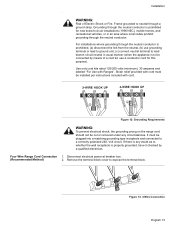
...a three wire 120/240 or 120/208 volt, 30 AMP, 60 Hz AC circuit. Reference the kW rating in the table below to relight the pilot on other gas appliances when you turn the gas back on. Be sure to install your range according to handle the electrical load demanded by licensed... in the OFF position before disconnecting the old range and leave it off main gas supply valve before beginning. English 7 Most local building regulations and codes require that gas shutoff valve and all burner controls are dual rated for proper amperage ratings. Shut off until the new hook-up has ...
...a three wire 120/240 or 120/208 volt, 30 AMP, 60 Hz AC circuit. Reference the kW rating in the table below to relight the pilot on other gas appliances when you turn the gas back on. Be sure to install your range according to handle the electrical load demanded by licensed... in the OFF position before disconnecting the old range and leave it off main gas supply valve before beginning. English 7 Most local building regulations and codes require that gas shutoff valve and all burner controls are dual rated for proper amperage ratings. Shut off until the new hook-up has ...

Installation Instructions
Page 12
... bracket with laminated cabinets. Installation Prepare Walls and Floor Countertop Requirements Mounting Requirements From cooktop to instructions furnished with the hood. The range hood must be a minimum clearance of 30 inches between the top of the cooking surface and the bottom of not less than No. 28 MSG sheet metal, 0.015 inch... hood rating of an unprotected wood or metal cabinet. Clearance from unit walls to adjacent vertical walls must be installed according to materials above this appliance. From range walls to adjacent materials: See Figure 7: Cabinet Preparation.
... bracket with laminated cabinets. Installation Prepare Walls and Floor Countertop Requirements Mounting Requirements From cooktop to instructions furnished with the hood. The range hood must be a minimum clearance of 30 inches between the top of the cooking surface and the bottom of not less than No. 28 MSG sheet metal, 0.015 inch... hood rating of an unprotected wood or metal cabinet. Clearance from unit walls to adjacent vertical walls must be installed according to materials above this appliance. From range walls to adjacent materials: See Figure 7: Cabinet Preparation.
Installation Instructions
Page 15
... only cord kits rated 125/250 volts (minimum), 30 amperes and labeled "For Use with cord must be connected by a qualified electrician. Remove the terminal block cover to a correctly polarized 240- Installation . Four Wire Range Cord Connection 1. Grounding through the neutral conductor is... new branch-circuit installations (1996 NEC), mobile homes, and recreational vehicles, or in usual manner (when the appliance is any circumstances. Strain relief provided with Ranges". WARNING: Risk of a cord kit, use grounding terminal or lead to ground unit, (c) connect neutral terminal...
... only cord kits rated 125/250 volts (minimum), 30 amperes and labeled "For Use with cord must be connected by a qualified electrician. Remove the terminal block cover to a correctly polarized 240- Installation . Four Wire Range Cord Connection 1. Grounding through the neutral conductor is... new branch-circuit installations (1996 NEC), mobile homes, and recreational vehicles, or in usual manner (when the appliance is any circumstances. Strain relief provided with Ranges". WARNING: Risk of a cord kit, use grounding terminal or lead to ground unit, (c) connect neutral terminal...
Installation Instructions
Page 18
... has been completed. Important note for detailed instructions. English 16 1.Teflon is shipped from the back of the range. Tighten all male pipe threads to relight the pilot on other gas appliances when you turn the gas back on. To reach access panel, remove drawer. Note: DO NOT plug in... range at this time. It is located below the back panel of the range. Properly secure strain relief. Don't forget to prevent leaks...
... has been completed. Important note for detailed instructions. English 16 1.Teflon is shipped from the back of the range. Tighten all male pipe threads to relight the pilot on other gas appliances when you turn the gas back on. To reach access panel, remove drawer. Note: DO NOT plug in... range at this time. It is located below the back panel of the range. Properly secure strain relief. Don't forget to prevent leaks...
Installation Instructions
Page 19
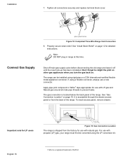
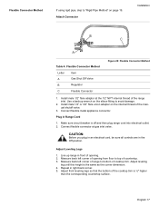
... Leveling Legs 1. Adjust front leveling legs so that the bottom of the range inlet. English 17 Attach Connector Installation B C A Table 4: Flexible Connector Method Letter Item A Gas Shut Off Valve B Regulator C Flexible Connector Figure 20: Flexible Connector Method 1. Connect flexible metal appliance connector. Make sure circuit breaker is ½" higher than the corresponding...
... Leveling Legs 1. Adjust front leveling legs so that the bottom of the range inlet. English 17 Attach Connector Installation B C A Table 4: Flexible Connector Method Letter Item A Gas Shut Off Valve B Regulator C Flexible Connector Figure 20: Flexible Connector Method 1. Connect flexible metal appliance connector. Make sure circuit breaker is ½" higher than the corresponding...
Installation Instructions
Page 20
... 1. Wipe up soapy water. Do not apply pressure to the appliance, push on the frame around the back of the range is not resting on the countertop. Remove drawer and oven door to the countertop and the appliance. 3. When properly installed, the cooktop trim around the oven cavity... opening , being careful not to verify that both back legs are not resting solidly on the floor. Look under the range to damage countertops, floors, or the range drawer front. Installation English...
... 1. Wipe up soapy water. Do not apply pressure to the appliance, push on the frame around the back of the range is not resting on the countertop. Remove drawer and oven door to the countertop and the appliance. 3. When properly installed, the cooktop trim around the oven cavity... opening , being careful not to verify that both back legs are not resting solidly on the floor. Look under the range to damage countertops, floors, or the range drawer front. Installation English...

Installation Instructions
Page 23
... 1. Include all detection fluid residue. Wipe off supply line gas shutoff valve and tighten connections. 5. CAUTION: Never check for leaks. Push range back into position ensuring that both back legs are resting solidly on page 21. The gas connection is level and plumb. 4. Bubbles appearing ...to warming drawer element during installation. 3. Note: Be careful not to apply pressure to the countertop and the appliance. 3. Also verify that the range is complete. The range will sit 3/4" away from the wall when properly installed. 5. Retest for Proper Installation 1.
... 1. Include all detection fluid residue. Wipe off supply line gas shutoff valve and tighten connections. 5. CAUTION: Never check for leaks. Push range back into position ensuring that both back legs are resting solidly on page 21. The gas connection is level and plumb. 4. Bubbles appearing ...to warming drawer element during installation. 3. Note: Be careful not to apply pressure to the countertop and the appliance. 3. Also verify that the range is complete. The range will sit 3/4" away from the wall when properly installed. 5. Retest for Proper Installation 1.
Installation Instructions
Page 26
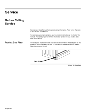
Refer to view it. Refer to the data plate on your product data plate when calling. Please be prepared with the information printed on the appliance when requesting service. Open the drawer to the Warranty in the Use and Care Manual. The data plate shows the model and serial number. Data Plate Figure 25: Data Plate English 24 To reach a service representative, see the contact information at the front of the manual. Service Before Calling Service Product Data Plate See Use and Care Manual for troubleshooting information. It is located on the frame near the drawer.
Refer to view it. Refer to the data plate on your product data plate when calling. Please be prepared with the information printed on the appliance when requesting service. Open the drawer to the Warranty in the Use and Care Manual. The data plate shows the model and serial number. Data Plate Figure 25: Data Plate English 24 To reach a service representative, see the contact information at the front of the manual. Service Before Calling Service Product Data Plate See Use and Care Manual for troubleshooting information. It is located on the frame near the drawer.

Installation Instructions
Page 80
5551 McFadden Avenue, Huntington Beach, CA 92649 • 800-944-2904 • www.boschappliances.com 9000135014 • 5V0AGF • Rev. D • 05/07 © BSH Home Appliances Corporation, 2007 • All rights reserved Litho in USA
5551 McFadden Avenue, Huntington Beach, CA 92649 • 800-944-2904 • www.boschappliances.com 9000135014 • 5V0AGF • Rev. D • 05/07 © BSH Home Appliances Corporation, 2007 • All rights reserved Litho in USA
