Installation Guide
Page 7
... mains cable or mains plug is working correctly. If the device does not work to be carried out by qualified service personnel. - Bosch Sicherheitssysteme GmbH Installation Guide F.01U.033.308 | V7 | 2009.09 Observe warnings Observe all instructions for the device to be serviced. ... Do not attempt to tip over. 5. rain, snow etc.). - The device has fallen to the manufacturer's instructions. Spare parts If spare parts are required, service personnel must be carried out with water and/or has been exposed to extreme environmental conditions (e.g. Unplug the device...
... mains cable or mains plug is working correctly. If the device does not work to be carried out by qualified service personnel. - Bosch Sicherheitssysteme GmbH Installation Guide F.01U.033.308 | V7 | 2009.09 Observe warnings Observe all instructions for the device to be serviced. ... Do not attempt to tip over. 5. rain, snow etc.). - The device has fallen to the manufacturer's instructions. Spare parts If spare parts are required, service personnel must be carried out with water and/or has been exposed to extreme environmental conditions (e.g. Unplug the device...

Installation Guide
Page 9
... device. When handling electrostatically sensitive printed circuits, grounded anti-static wrist bands must only be worn and the ESD safety precautions observed. Bosch Sicherheitssysteme GmbH Installation Guide F.01U.033.308 | V7 | 2009.09 Overloading - Electrostatically sensitive device: To avoid electrostatic discharges, the ...ON/OFF) is pulled out of the socket, the supply of mains supply: Voltage is applied as soon as you may touch parts that operate at high-voltage or cause a short circuit, which may result in humid locations. Mains cable and mains cable protectors ...
... device. When handling electrostatically sensitive printed circuits, grounded anti-static wrist bands must only be worn and the ESD safety precautions observed. Bosch Sicherheitssysteme GmbH Installation Guide F.01U.033.308 | V7 | 2009.09 Overloading - Electrostatically sensitive device: To avoid electrostatic discharges, the ...ON/OFF) is pulled out of the socket, the supply of mains supply: Voltage is applied as soon as you may touch parts that operate at high-voltage or cause a short circuit, which may result in humid locations. Mains cable and mains cable protectors ...
Installation Guide
Page 11
...Introduction | en 11 2 2.1 2.2 2.3 2.4 Introduction System Description The video system is within the values specified for the device. If parts are recommended: - Mains networks with voltage peaks, voltage dropout and voltage dropoff: Use of an online UPS is damaged during transport, ...and/or loss of the mains network, the following uninterruptible power supplies are missing, inform your customer service representative or a Bosch Security Systems salesperson. Depending on devices (e.g. Retain the box and the packaging material for the device. Unpacking Check the packaging...
...Introduction | en 11 2 2.1 2.2 2.3 2.4 Introduction System Description The video system is within the values specified for the device. If parts are recommended: - Mains networks with voltage peaks, voltage dropout and voltage dropoff: Use of an online UPS is damaged during transport, ...and/or loss of the mains network, the following uninterruptible power supplies are missing, inform your customer service representative or a Bosch Security Systems salesperson. Depending on devices (e.g. Retain the box and the packaging material for the device. Unpacking Check the packaging...
Installation Guide
Page 16
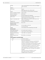
...as per EN 50130-4 A2: 2003 Chapter 8.3.4. 16 en | Introduction DiBos/DiBos Micro RS 232 USB 2.0 2 (for connecting Bosch security systems and Allegiant matrix switches) 5 DVD burner Power Internal. EU EMC Directive 89/336/EEC Interference immunity: Conformance with ...A2, Class B Mains power fluctuations: EN 61000-3-2 Voltage fluctuations: EN 61000-3-3 F.01U.033.308 | V7 | 2009.09 Installation Guide Bosch Sicherheitssysteme GmbH USA FCC Part 15, Class A - The UPS is required. For information on the model Environmental Operating temperature 5 °C to 40 °C (...
...as per EN 50130-4 A2: 2003 Chapter 8.3.4. 16 en | Introduction DiBos/DiBos Micro RS 232 USB 2.0 2 (for connecting Bosch security systems and Allegiant matrix switches) 5 DVD burner Power Internal. EU EMC Directive 89/336/EEC Interference immunity: Conformance with ...A2, Class B Mains power fluctuations: EN 61000-3-2 Voltage fluctuations: EN 61000-3-3 F.01U.033.308 | V7 | 2009.09 Installation Guide Bosch Sicherheitssysteme GmbH USA FCC Part 15, Class A - The UPS is required. For information on the model Environmental Operating temperature 5 °C to 40 °C (...

Installation Guide
Page 20
... Order information Norton AntiVirus McAfee VirusScan Trend Micro The current order information is tested in the datasheet. F.01U.033.308 | V7 | 2009.09 Installation Guide Bosch Sicherheitssysteme GmbH 20 en | Introduction DiBos/DiBos Micro Mechanical data Dimensions (H x W x D) Weight 11.5 x 48.0 x 43 cm (4.5 x 19 x 16.9 inches), also 19" rack installation Approx....5 kg (approx. 25 lb), depending on how to connect a UPS to DiBos, please refer to 80%, non-condensing Electromagnetic compatibility (EMC) - Please see: www.bosch-securitysystems.com. USA FCC Part 15, Class B -
... Order information Norton AntiVirus McAfee VirusScan Trend Micro The current order information is tested in the datasheet. F.01U.033.308 | V7 | 2009.09 Installation Guide Bosch Sicherheitssysteme GmbH 20 en | Introduction DiBos/DiBos Micro Mechanical data Dimensions (H x W x D) Weight 11.5 x 48.0 x 43 cm (4.5 x 19 x 16.9 inches), also 19" rack installation Approx....5 kg (approx. 25 lb), depending on how to connect a UPS to DiBos, please refer to 80%, non-condensing Electromagnetic compatibility (EMC) - Please see: www.bosch-securitysystems.com. USA FCC Part 15, Class B -

Installation Guide
Page 95
... the dialog box and click the button. Input your entries in the lower part of the dialog box that opens. Bosch Sicherheitssysteme GmbH Installation Guide F.01U.033.308 | V7 | 2009.09 Existing remote stations are displayed in the list field. Data on existing remote stations can ...
... the dialog box and click the button. Input your entries in the lower part of the dialog box that opens. Bosch Sicherheitssysteme GmbH Installation Guide F.01U.033.308 | V7 | 2009.09 Existing remote stations are displayed in the list field. Data on existing remote stations can ...

Installation Guide
Page 107
... to carry out (see also Section 6.10 Creating Authorization Levels). You can only be protected with another user. 7 Save The entries are saved. Bosch Sicherheitssysteme GmbH Installation Guide F.01U.033.308 | V7 | 2009.09 The user with the "Administrator" authorization level must be carried out by users ...the user. 6 Dual authorization Activate this function when the user may only log on . Click New and enter a user name in the lower part of the user. NOTICE! Every user is only known to those persons who are logged on to the system together with a password. In the...
... to carry out (see also Section 6.10 Creating Authorization Levels). You can only be protected with another user. 7 Save The entries are saved. Bosch Sicherheitssysteme GmbH Installation Guide F.01U.033.308 | V7 | 2009.09 The user with the "Administrator" authorization level must be carried out by users ...the user. 6 Dual authorization Activate this function when the user may only log on . Click New and enter a user name in the lower part of the user. NOTICE! Every user is only known to those persons who are logged on to the system together with a password. In the...
Installation Guide
Page 109
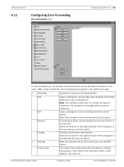
...must be started up. The recipient's messenger service must not contain any special characters. Opens a dialog box. Test the connection to be edited. Bosch Sicherheitssysteme GmbH Installation Guide F.01U.033.308 | V7 | 2009.09 Error forwarding also applies to the malfunction relay. 1 Informing Specify the locations ... be removed from the list of malfunction, for the e-mail server and the SMS service. Select the recipient in the right-hand part of the dialog box in the overview and click the button. The e-mail server setup opens after the button is clicked. Select ...
...must be started up. The recipient's messenger service must not contain any special characters. Opens a dialog box. Test the connection to be edited. Bosch Sicherheitssysteme GmbH Installation Guide F.01U.033.308 | V7 | 2009.09 Error forwarding also applies to the malfunction relay. 1 Informing Specify the locations ... be removed from the list of malfunction, for the e-mail server and the SMS service. Select the recipient in the right-hand part of the dialog box in the overview and click the button. The e-mail server setup opens after the button is clicked. Select ...

Installation Guide
Page 131
... 2 9 5 7 V24 3 (ST3) 1 5 9 9 V24 (ST3) E1 E2 E3 E4 PC 6 3 1 6 5 8 4 OPTO 6 OPTO 4 1 Video system 2 COM x 3 9-pin 4 Connection cable, 9-pin, part no. 4.998.079.686 (1:1 connection) 5 OVS 1 BR1 and BR2: Position 1/2 ST3: Pin 2 = transmit line, Pin 3 = receive line 6 Max. 1000 m 7 OVS 2 BR1 and BR2: Position 2/3 ST3... interface processor. Connection principle: 2 2 4 2 1 3 3 5 6 1 Video system 2 Max. 15 m 3 OVS Connection details: 4 Max. 1000 m 5 Interface processor 6 ATM1 - Bosch Sicherheitssysteme GmbH Installation Guide F.01U.033.308 | V7 | 2009.09
... 2 9 5 7 V24 3 (ST3) 1 5 9 9 V24 (ST3) E1 E2 E3 E4 PC 6 3 1 6 5 8 4 OPTO 6 OPTO 4 1 Video system 2 COM x 3 9-pin 4 Connection cable, 9-pin, part no. 4.998.079.686 (1:1 connection) 5 OVS 1 BR1 and BR2: Position 1/2 ST3: Pin 2 = transmit line, Pin 3 = receive line 6 Max. 1000 m 7 OVS 2 BR1 and BR2: Position 2/3 ST3... interface processor. Connection principle: 2 2 4 2 1 3 3 5 6 1 Video system 2 Max. 15 m 3 OVS Connection details: 4 Max. 1000 m 5 Interface processor 6 ATM1 - Bosch Sicherheitssysteme GmbH Installation Guide F.01U.033.308 | V7 | 2009.09

Installation Guide
Page 133
DiBos/DiBos Micro Connections | en 133 5 Connection cable, 9-pin, part no. 4.998.079.686 (1:1 connection) 6 9-pin 11 ATM1 NOTICE! Bosch Sicherheitssysteme GmbH Installation Guide F.01U.033.308 | V7 | 2009.09 By re-plugging the bridges BR1 and BR2 in the OVS, it is possible to swap over the transmit and receive lines.
DiBos/DiBos Micro Connections | en 133 5 Connection cable, 9-pin, part no. 4.998.079.686 (1:1 connection) 6 9-pin 11 ATM1 NOTICE! Bosch Sicherheitssysteme GmbH Installation Guide F.01U.033.308 | V7 | 2009.09 By re-plugging the bridges BR1 and BR2 in the OVS, it is possible to swap over the transmit and receive lines.