

Installation Instructions
Page 3
... 17 2. Other required accessories from specialist outlets 17 4. Contents Before you Begin 5 Definitions 5 Important information 5 Installation options 6 Individual unit 6 SideĆbyĆSide 6 Individual appliances with partition 6 At the end of the kitchen units 6 Installation location 7 Installation room 7 Installation cavity 7 Furniture/fixtures 7 Base 7 Connecting the power 8 Additional grounding procedure 8 Grounding...
... 17 2. Other required accessories from specialist outlets 17 4. Contents Before you Begin 5 Definitions 5 Important information 5 Installation options 6 Individual unit 6 SideĆbyĆSide 6 Individual appliances with partition 6 At the end of the kitchen units 6 Installation location 7 Installation room 7 Installation cavity 7 Furniture/fixtures 7 Base 7 Connecting the power 8 Additional grounding procedure 8 Grounding...
Installation Instructions
Page 4
...ĆbyĆSide installation 25 11. Preparing the furniture doors 31 19. Transport of air separator 40 30. Attaching the appliance to the appliance 28 16. Changing over the door hinges 20 6. Attaching an alternative antiĆtip device 24 8. Pushing the...23. Shorten the finger guard 36 24. Adjusting the door opening angle 41 31. Attaching the individual appliance to the furniture door 32 21. Mounting of the appliance 18 3. Commissioning the Appliance 30 18. Attaching the adjusting rail to the side of the cavity 27 14. Preparing the installation ...
...ĆbyĆSide installation 25 11. Preparing the furniture doors 31 19. Transport of air separator 40 30. Attaching the appliance to the appliance 28 16. Changing over the door hinges 20 6. Attaching an alternative antiĆtip device 24 8. Pushing the...23. Shorten the finger guard 36 24. Adjusting the door opening angle 41 31. Attaching the individual appliance to the furniture door 32 21. Mounting of the appliance 18 3. Commissioning the Appliance 30 18. Attaching the adjusting rail to the side of the cavity 27 14. Preparing the installation ...
Installation Instructions
Page 5
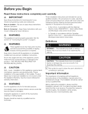
... be secured to prevent the possibility of the installer. latest edition/State and Municipal codes and/or local codes. e WARNING These appliances are intended for its intended purpose. Proper installation is used to draw the user's attention to improper installation is completely installed and... repair or replace electric service cords that minor or moderate injuries or damage may occur as a result of not observing this appliance, and to leave these instructions for warranty information. These installation instructions are topĆheavy and must comply with local codes and...
... be secured to prevent the possibility of the installer. latest edition/State and Municipal codes and/or local codes. e WARNING These appliances are intended for its intended purpose. Proper installation is used to draw the user's attention to improper installation is completely installed and... repair or replace electric service cords that minor or moderate injuries or damage may occur as a result of not observing this appliance, and to leave these instructions for warranty information. These installation instructions are topĆheavy and must comply with local codes and...
Installation Instructions
Page 6
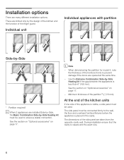
...exact size. 6 When dimensioning the partition for model 4, note the thickness of the appliance is placed in the cavity. Individual unit Individual appliances with partition 1. 2. See the section on Optional accessories" on page 17. - i When 2 appliances are limited only by ĆSide * * * Partition required! Use the Extreme ... page 17. 3. 4. The side panel must be connected firmly to the wall, the floor and overhead furniture/fixtures before the appliance is visible, a side panel must be used to prevent damage if the doors are many different installation options.
...exact size. 6 When dimensioning the partition for model 4, note the thickness of the appliance is placed in the cavity. Individual unit Individual appliances with partition 1. 2. See the section on Optional accessories" on page 17. - i When 2 appliances are limited only by ĆSide * * * Partition required! Use the Extreme ... page 17. 3. 4. The side panel must be connected firmly to the wall, the floor and overhead furniture/fixtures before the appliance is visible, a side panel must be used to prevent damage if the doors are many different installation options.

Installation Instructions
Page 7
...installed securely and functions properly, the base must be the same height as an oven, radiator, etc. d WARNING d Do not install the appliance: - outdoors, - i The side walls of the furniture front. If installation next to observe the specified dimensions of the installation cavity for a... troubleĆfree installation of the appliance and for the subsequent general view of the cavity must be flush. in doubt, contact an architect or a building expert. ...
...installed securely and functions properly, the base must be the same height as an oven, radiator, etc. d WARNING d Do not install the appliance: - outdoors, - i The side walls of the furniture front. If installation next to observe the specified dimensions of the installation cavity for a... troubleĆfree installation of the appliance and for the subsequent general view of the cavity must be flush. in doubt, contact an architect or a building expert. ...
Installation Instructions
Page 8
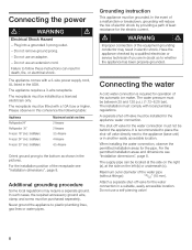
...use an adapter. - The receptacle must be installed by a licensed electrician only. Additional grounding procedure3. Grounding instruction This appliance must be grounded. In the event of a malfunction or breakdown, grounding will reduce the risk of electric shock by ...piercing valve! 8 IceMaker) Maximum load at the side on the left (b) or underneath (c). The installation must be behind the appliance. The appliance comes with local plumbing regulations. d WARNING d Electrical Shock Hazard - Maximum outer diameter of the receptacle see Installation dimensions",...
...use an adapter. - The receptacle must be installed by a licensed electrician only. Additional grounding procedure3. Grounding instruction This appliance must be grounded. In the event of a malfunction or breakdown, grounding will reduce the risk of electric shock by ...piercing valve! 8 IceMaker) Maximum load at the side on the left (b) or underneath (c). The installation must be behind the appliance. The appliance comes with local plumbing regulations. d WARNING d Electrical Shock Hazard - Maximum outer diameter of the receptacle see Installation dimensions",...
Installation Instructions
Page 9
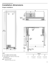
Legend: A Area for installation of the water connection B Area for installation of the power connection D Opening depth of the cavity must be flush. Single installation6. Appliance 18" 24" 30" X 18" (457 mm) 24 (610 mm) 30" (762 mm) Y 9" (229 mm) 12" (305 mm) 15" (381 mm) 9 Side wall of niche, depending on kitchen design (see DESIGN GUIDE) D = 24" (610 mm) minimum NOTE: Cavity must be suare. Installation dimensions5.
Legend: A Area for installation of the water connection B Area for installation of the power connection D Opening depth of the cavity must be flush. Single installation6. Appliance 18" 24" 30" X 18" (457 mm) 24 (610 mm) 30" (762 mm) Y 9" (229 mm) 12" (305 mm) 15" (381 mm) 9 Side wall of niche, depending on kitchen design (see DESIGN GUIDE) D = 24" (610 mm) minimum NOTE: Cavity must be suare. Installation dimensions5.
Installation Instructions
Page 10
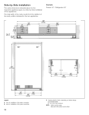
...: Freezer 18" / Refrigerator 30" Legend: A Area for installation of the water connection B Area for the two appliances. Side wall of niche, depending on kitchen design (see DESIGN GUIDE) D = 24" (610 mm) minimum NOTE: Cavity must be suare. SideĆbyĆ...Side installation The cavity dimensions indicated above for the respective appliance apply to a SideĆbyĆSide installation of the cavity widths indicated for installation of the power connection 10 D Opening depth of the cavity...
...: Freezer 18" / Refrigerator 30" Legend: A Area for installation of the water connection B Area for the two appliances. Side wall of niche, depending on kitchen design (see DESIGN GUIDE) D = 24" (610 mm) minimum NOTE: Cavity must be suare. SideĆbyĆ...Side installation The cavity dimensions indicated above for the respective appliance apply to a SideĆbyĆSide installation of the cavity widths indicated for installation of the power connection 10 D Opening depth of the cavity...

Installation Instructions
Page 12
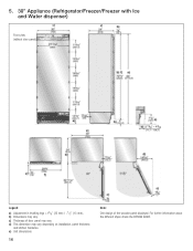
Appliance dimensions7. 1. 18" Appliance (Freezer/Freezer with Ice and Water dispenser) e) e) Front view (without door panel) Legend: a) Adjustment in levelling legs +13/8" (35 mm) / -1/2" (13 mm). d) This dimension may vary depending on installation, panel thickness and kitchen hardware. 12 e) Unit dimensions Note: One design of door panel may vary. For further information about the different styles check the DESIGN GUIDE. c) Thickness of the wooden panel displayed. b) Dimensions may vary.
Appliance dimensions7. 1. 18" Appliance (Freezer/Freezer with Ice and Water dispenser) e) e) Front view (without door panel) Legend: a) Adjustment in levelling legs +13/8" (35 mm) / -1/2" (13 mm). d) This dimension may vary depending on installation, panel thickness and kitchen hardware. 12 e) Unit dimensions Note: One design of door panel may vary. For further information about the different styles check the DESIGN GUIDE. c) Thickness of the wooden panel displayed. b) Dimensions may vary.
Installation Instructions
Page 13
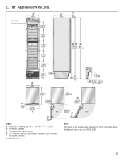
e) Unit dimensions Note: One design of door panel may vary. b) Dimensions may vary depending on installation, panel thickness and kitchen hardware. d) This dimension may vary. For further information about the different styles check the DESIGN GUIDE. 13 2. 18" Appliance (Wine unit) e) e) Front view (without door panel) Legend: a) Adjustment in levelling legs +13/8" (35 mm) / -1/2" (13 mm). c) Thickness of the wooden panel displayed.
e) Unit dimensions Note: One design of door panel may vary. b) Dimensions may vary depending on installation, panel thickness and kitchen hardware. d) This dimension may vary. For further information about the different styles check the DESIGN GUIDE. 13 2. 18" Appliance (Wine unit) e) e) Front view (without door panel) Legend: a) Adjustment in levelling legs +13/8" (35 mm) / -1/2" (13 mm). c) Thickness of the wooden panel displayed.
Installation Instructions
Page 14
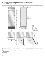
d) This dimension may vary. e) Unit dimensions 14 Note: One design of door panel may vary. c) Thickness of the wooden panel displayed. For further information about the different styles check the DESIGN GUIDE. b) Dimensions may vary depending on installation, panel thickness and kitchen hardware. 3. 24" Appliance (Refrigerator/Freezer/Freezer with Ice and Water dispenser) e) e) Front view (without door panel) Legend: a) Adjustment in levelling legs +13/8" (35 mm) / -1/2" (13 mm).
d) This dimension may vary. e) Unit dimensions 14 Note: One design of door panel may vary. c) Thickness of the wooden panel displayed. For further information about the different styles check the DESIGN GUIDE. b) Dimensions may vary depending on installation, panel thickness and kitchen hardware. 3. 24" Appliance (Refrigerator/Freezer/Freezer with Ice and Water dispenser) e) e) Front view (without door panel) Legend: a) Adjustment in levelling legs +13/8" (35 mm) / -1/2" (13 mm).

Installation Instructions
Page 15
d) This dimension may vary. e) Unit dimensions Note: One design of door panel may vary depending on installation, panel thickness and kitchen hardware. c) Thickness of the wooden panel displayed. b) Dimensions may vary. For further information about the different styles check the DESIGN GUIDE. 15 4. 24" Appliance (Wine unit) e) e) Front view (without door panel) Legend: a) Adjustment in levelling legs +13/8" (35 mm) / -1/2" (13 mm).
d) This dimension may vary. e) Unit dimensions Note: One design of door panel may vary depending on installation, panel thickness and kitchen hardware. c) Thickness of the wooden panel displayed. b) Dimensions may vary. For further information about the different styles check the DESIGN GUIDE. 15 4. 24" Appliance (Wine unit) e) e) Front view (without door panel) Legend: a) Adjustment in levelling legs +13/8" (35 mm) / -1/2" (13 mm).
Installation Instructions
Page 16
c) Thickness of the wooden panel displayed. d) This dimension may vary. e) Unit dimensions 16 Note: One design of door panel may vary depending on installation, panel thickness and kitchen hardware. For further information about the different styles check the DESIGN GUIDE. 5. 30" Appliance (Refrigerator/Freezer/Freezer with Ice and Water dispenser) e) e) Front view (without door panel) Legend: a) Adjustment in levelling legs +13/8" (35 mm) / -1/2" (13 mm). b) Dimensions may vary.
c) Thickness of the wooden panel displayed. d) This dimension may vary. e) Unit dimensions 16 Note: One design of door panel may vary depending on installation, panel thickness and kitchen hardware. For further information about the different styles check the DESIGN GUIDE. 5. 30" Appliance (Refrigerator/Freezer/Freezer with Ice and Water dispenser) e) e) Front view (without door panel) Legend: a) Adjustment in levelling legs +13/8" (35 mm) / -1/2" (13 mm). b) Dimensions may vary.
Installation Instructions
Page 17
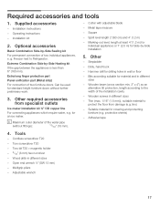
...mm). - Torx screwdriver T20 - Other - Can be used for SideĆby ĆSide Heating kit If the gap between the appliances is less than 6" (160 mm). lino) - Wood drills in different sizes - Adjustable wrench 17 Other required accessories from damage (e.g. ... tape 4. Wooden beam (cross section min. 3" x 4") as an alternative tilt protection, length according to the width of two individual appliances, e. Cordless screwdriver T20 - Basic Combination SideĆbyĆSide Sealing kit For permanent connection of the installation cavity - Extra long ...
...mm). - Torx screwdriver T20 - Other - Can be used for SideĆby ĆSide Heating kit If the gap between the appliances is less than 6" (160 mm). lino) - Wood drills in different sizes - Adjustable wrench 17 Other required accessories from damage (e.g. ... tape 4. Wooden beam (cross section min. 3" x 4") as an alternative tilt protection, length according to the width of two individual appliances, e. Cordless screwdriver T20 - Basic Combination SideĆbyĆSide Sealing kit For permanent connection of the installation cavity - Extra long ...
Installation Instructions
Page 18
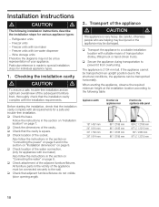
... subsequent furniture front, thoroughly check that the installation cavity complies with iceĆwater dispenser - q Transport the appliance to the structural conditions, the appliance can be transported in the section on Installation location" on page 8. Checking the installation cavity d CAUTION d... mm 89" / 2260 mm 911/4" / 2315 mm 18 Freezer units with all requirements for appliances with the installation requirements. q Check the base. q Secure the appliance during transportation to the wall. All furniture parts in the section on Installation dimensions" on page...
... subsequent furniture front, thoroughly check that the installation cavity complies with iceĆwater dispenser - q Transport the appliance to the structural conditions, the appliance can be transported in the section on Installation location" on page 8. Checking the installation cavity d CAUTION d... mm 89" / 2260 mm 911/4" / 2315 mm 18 Freezer units with all requirements for appliances with the installation requirements. q Check the base. q Secure the appliance during transportation to the wall. All furniture parts in the section on Installation dimensions" on page...
Installation Instructions
Page 19
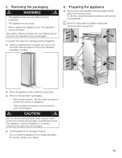
... fastening screws and remove the stop parts in doubt, contact your dealer. 19 The appliance is being unpacked. - q Move the appliance with adhesive tape in transit. Be careful, otherwise people who are helping may be injured or the... WARNING d - Take supplied accessories out of protection parts of carpet, lino, etc. When opening the appliance door, the appliance may be damaged. q Check appliance for damage in front of appliance. - The appliance may be damaged. d CAUTION d Do not remove transportation safety devices which attach the furniture fronts. q...
... fastening screws and remove the stop parts in doubt, contact your dealer. 19 The appliance is being unpacked. - q Move the appliance with adhesive tape in transit. Be careful, otherwise people who are helping may be injured or the... WARNING d - Take supplied accessories out of protection parts of carpet, lino, etc. When opening the appliance door, the appliance may be damaged. q Check appliance for damage in front of appliance. - The appliance may be damaged. d CAUTION d Do not remove transportation safety devices which attach the furniture fronts. q...
Installation Instructions
Page 21
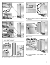
q Change over the hinge angle. q Fix the hinges on the hinge. Change the hinges crosswise! q Mount the grill completely. Tighten the screw from 0 to I. 21 q Span the spring on the appliance. q Fit the plastic part of the grill. q Fix the door. q Change over the fixation parts on the door.
q Change over the hinge angle. q Fix the hinges on the hinge. Change the hinges crosswise! q Mount the grill completely. Tighten the screw from 0 to I. 21 q Span the spring on the appliance. q Fit the plastic part of the grill. q Fix the door. q Change over the fixation parts on the door.
Installation Instructions
Page 22
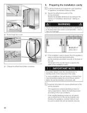
...(609,6-647,7) q If the installation cavity is equal to the base or the wall. The length of the wooden beam is deeper than the appliance, place a solid wooden beam behind the antiĆtipĆbrackets and attach securely to the width of the cavity. i Important information for ...various applications. The supplied set contains fastening screws for secure attachment of the antiĆtip brackets and therefore the appliance, another method must be used to fasten the antiĆtipĆbrackets to existing studs on page 9. q Fix the hinge box cover. ...
...(609,6-647,7) q If the installation cavity is equal to the base or the wall. The length of the wooden beam is deeper than the appliance, place a solid wooden beam behind the antiĆtipĆbrackets and attach securely to the width of the cavity. i Important information for ...various applications. The supplied set contains fastening screws for secure attachment of the antiĆtip brackets and therefore the appliance, another method must be used to fasten the antiĆtipĆbrackets to existing studs on page 9. q Fix the hinge box cover. ...
Installation Instructions
Page 24
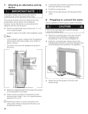
... beam can be attached securely. 24 q Attach the wooden beam to the cavity width, thereby ensuring that there is no play between the appliance and the antiĆtip device. q Install the connecting pipe. q Select screws according to the connecting pipe when pushing in the beam.... The beam must cover the appliance by the manufacturer of the cavity. q Attach the connecting pipe to the required length. i Note - Always observe the indicated gap dimensions to ...
... beam can be attached securely. 24 q Attach the wooden beam to the cavity width, thereby ensuring that there is no play between the appliance and the antiĆtip device. q Install the connecting pipe. q Select screws according to the connecting pipe when pushing in the beam.... The beam must cover the appliance by the manufacturer of the cavity. q Attach the connecting pipe to the required length. i Note - Always observe the indicated gap dimensions to ...

Installation Instructions
Page 25
... corners of the installation cavity, attach the supplied protective brackets with adhesive tape. 11. 9. Pushing the appliance into the installation cavity d CAUTION d Caution when pushing the appliance into the installation cavity. 25 Attaching the edge protection 10.SideĆbyĆSide installation i If ...attached to the installation cavity adjust height adjustable wheels before you move the appliance into the installation cavity. i When the floor or the appliance is intended, now connect the two appliances together. See the Installation Manual for the SideĆby Ć...
... corners of the installation cavity, attach the supplied protective brackets with adhesive tape. 11. 9. Pushing the appliance into the installation cavity d CAUTION d Caution when pushing the appliance into the installation cavity. 25 Attaching the edge protection 10.SideĆbyĆSide installation i If ...attached to the installation cavity adjust height adjustable wheels before you move the appliance into the installation cavity. i When the floor or the appliance is intended, now connect the two appliances together. See the Installation Manual for the SideĆby Ć...