

Installation Instructions
Page 3
... room 7 Installation cavity 7 Furniture/fixtures 7 Base 7 Connecting the power 8 Additional grounding procedure 8 Grounding instruction 8 Connecting the water 8 Installation dimensions 9 Single installation 9 SideĆbyĆSide installation 10 Water connection 11 Appliance dimensions 12 1. 18" Appliance (Freezer/Freezer with Ice and Water dispenser 12 2. 18" Appliance (Wine unit 13 3. 24" Appliance (Refrigerator...
... room 7 Installation cavity 7 Furniture/fixtures 7 Base 7 Connecting the power 8 Additional grounding procedure 8 Grounding instruction 8 Connecting the water 8 Installation dimensions 9 Single installation 9 SideĆbyĆSide installation 10 Water connection 11 Appliance dimensions 12 1. 18" Appliance (Freezer/Freezer with Ice and Water dispenser 12 2. 18" Appliance (Wine unit 13 3. 24" Appliance (Refrigerator...
Installation Instructions
Page 6
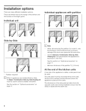
... SideĆbyĆSide, the Basic Combination SideĆby the design of the kitchen and the function of the finger guard. When dimensioning the partition for model 4, note the thickness of the appliance is square and the exact size. 6 Minimum thickness of the side panel are...must be connected firmly to prevent damage if the doors are many different installation options. See the section on Optional accessories" on page 17. - The dimensions of the partition 5/8" (16 mm). SideĆby ĆSide Heating kit if the gap between the appliances is placed in the cavity. i Note...
... SideĆbyĆSide, the Basic Combination SideĆby the design of the kitchen and the function of the finger guard. When dimensioning the partition for model 4, note the thickness of the appliance is square and the exact size. 6 Minimum thickness of the side panel are...must be connected firmly to prevent damage if the doors are many different installation options. See the section on Optional accessories" on page 17. - The dimensions of the partition 5/8" (16 mm). SideĆby ĆSide Heating kit if the gap between the appliances is placed in the cavity. i Note...

Installation Instructions
Page 7
.... On account of the heavy weight of ¾" (19 mm) is installed securely and functions properly, the base must be exposed to observe the specified dimensions of the installation cavity for a troubleĆfree installation of the appliance and for the loadĆbearing capacity at risk of the cavity must...
.... On account of the heavy weight of ¾" (19 mm) is installed securely and functions properly, the base must be exposed to observe the specified dimensions of the installation cavity for a troubleĆfree installation of the appliance and for the loadĆbearing capacity at risk of the cavity must...
Installation Instructions
Page 8
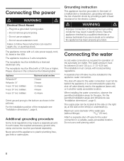
...off valve for the electric current. It is required for the appliance water connection. For the permitted installation areas and dimensions see "Installation dimensions", page 8. The appliance requires a 3Ćwire receptacle. Maximum outer diameter of the equipment grounding conductor may require ... seperately. Attach a separate shutĆoff valve must be installed for operation of the receptacle see Installation dimensions", page 8. The receptacle must comply with local plumbing regulations. When installing the water connection, observe the permitted...
...off valve for the electric current. It is required for the appliance water connection. For the permitted installation areas and dimensions see "Installation dimensions", page 8. The appliance requires a 3Ćwire receptacle. Maximum outer diameter of the equipment grounding conductor may require ... seperately. Attach a separate shutĆoff valve must be installed for operation of the receptacle see Installation dimensions", page 8. The receptacle must comply with local plumbing regulations. When installing the water connection, observe the permitted...
Installation Instructions
Page 10
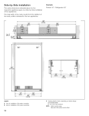
... niche, depending on kitchen design (see DESIGN GUIDE) D = 24" (610 mm) minimum NOTE: Cavity must be suare. SideĆbyĆSide installation The cavity dimensions indicated above for the respective appliance apply to a SideĆbyĆSide installation of the cavity must be flush. Side wall of two appliances.
... niche, depending on kitchen design (see DESIGN GUIDE) D = 24" (610 mm) minimum NOTE: Cavity must be suare. SideĆbyĆSide installation The cavity dimensions indicated above for the respective appliance apply to a SideĆbyĆSide installation of the cavity must be flush. Side wall of two appliances.

Installation Instructions
Page 12
For further information about the different styles check the DESIGN GUIDE. Appliance dimensions7. 1. 18" Appliance (Freezer/Freezer with Ice and Water dispenser) e) e) Front view (without door panel) Legend: a) Adjustment in levelling legs +13/8" (35 mm) / -1/2" (13 mm). c) Thickness of door panel may vary depending on installation, panel thickness and kitchen hardware. 12 e) Unit dimensions Note: One design of the wooden panel displayed. d) This dimension may vary. b) Dimensions may vary.
For further information about the different styles check the DESIGN GUIDE. Appliance dimensions7. 1. 18" Appliance (Freezer/Freezer with Ice and Water dispenser) e) e) Front view (without door panel) Legend: a) Adjustment in levelling legs +13/8" (35 mm) / -1/2" (13 mm). c) Thickness of door panel may vary depending on installation, panel thickness and kitchen hardware. 12 e) Unit dimensions Note: One design of the wooden panel displayed. d) This dimension may vary. b) Dimensions may vary.
Installation Instructions
Page 13
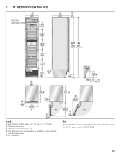
d) This dimension may vary. c) Thickness of the wooden panel displayed. For further information about the different styles check the DESIGN GUIDE. 13 b) Dimensions may vary. e) Unit dimensions Note: One design of door panel may vary depending on installation, panel thickness and kitchen hardware. 2. 18" Appliance (Wine unit) e) e) Front view (without door panel) Legend: a) Adjustment in levelling legs +13/8" (35 mm) / -1/2" (13 mm).
d) This dimension may vary. c) Thickness of the wooden panel displayed. For further information about the different styles check the DESIGN GUIDE. 13 b) Dimensions may vary. e) Unit dimensions Note: One design of door panel may vary depending on installation, panel thickness and kitchen hardware. 2. 18" Appliance (Wine unit) e) e) Front view (without door panel) Legend: a) Adjustment in levelling legs +13/8" (35 mm) / -1/2" (13 mm).
Installation Instructions
Page 14
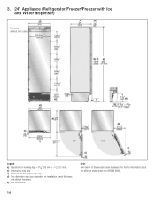
d) This dimension may vary. e) Unit dimensions 14 Note: One design of door panel may vary. For further information about the different styles check the DESIGN GUIDE. c) Thickness of the wooden panel displayed. b) Dimensions may vary depending on installation, panel thickness and kitchen hardware. 3. 24" Appliance (Refrigerator/Freezer/Freezer with Ice and Water dispenser) e) e) Front view (without door panel) Legend: a) Adjustment in levelling legs +13/8" (35 mm) / -1/2" (13 mm).
d) This dimension may vary. e) Unit dimensions 14 Note: One design of door panel may vary. For further information about the different styles check the DESIGN GUIDE. c) Thickness of the wooden panel displayed. b) Dimensions may vary depending on installation, panel thickness and kitchen hardware. 3. 24" Appliance (Refrigerator/Freezer/Freezer with Ice and Water dispenser) e) e) Front view (without door panel) Legend: a) Adjustment in levelling legs +13/8" (35 mm) / -1/2" (13 mm).

Installation Instructions
Page 15
4. 24" Appliance (Wine unit) e) e) Front view (without door panel) Legend: a) Adjustment in levelling legs +13/8" (35 mm) / -1/2" (13 mm). d) This dimension may vary. c) Thickness of the wooden panel displayed. e) Unit dimensions Note: One design of door panel may vary. For further information about the different styles check the DESIGN GUIDE. 15 b) Dimensions may vary depending on installation, panel thickness and kitchen hardware.
4. 24" Appliance (Wine unit) e) e) Front view (without door panel) Legend: a) Adjustment in levelling legs +13/8" (35 mm) / -1/2" (13 mm). d) This dimension may vary. c) Thickness of the wooden panel displayed. e) Unit dimensions Note: One design of door panel may vary. For further information about the different styles check the DESIGN GUIDE. 15 b) Dimensions may vary depending on installation, panel thickness and kitchen hardware.
Installation Instructions
Page 16
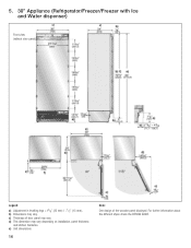
d) This dimension may vary. b) Dimensions may vary depending on installation, panel thickness and kitchen hardware. For further information about the different styles check the DESIGN GUIDE. e) Unit dimensions 16 Note: One design of door panel may vary. c) Thickness of the wooden panel displayed. 5. 30" Appliance (Refrigerator/Freezer/Freezer with Ice and Water dispenser) e) e) Front view (without door panel) Legend: a) Adjustment in levelling legs +13/8" (35 mm) / -1/2" (13 mm).
d) This dimension may vary. b) Dimensions may vary depending on installation, panel thickness and kitchen hardware. For further information about the different styles check the DESIGN GUIDE. e) Unit dimensions 16 Note: One design of door panel may vary. c) Thickness of the wooden panel displayed. 5. 30" Appliance (Refrigerator/Freezer/Freezer with Ice and Water dispenser) e) e) Front view (without door panel) Legend: a) Adjustment in levelling legs +13/8" (35 mm) / -1/2" (13 mm).
Installation Instructions
Page 18
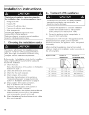
...262;free installation and an optimum overall view of the subsequent furniture front, thoroughly check that the cavity is very heavy. q Check the dimensions of the socket. Also follow the instructions in the section on Connecting the water" on page 8. Transport of the water connection. (...appliances with ice maker) Also follow the instructions in the section on Connecting the power" on page 8 and in the section on Installation dimensions" on page 7. q Check location of the appliance d CAUTION d The appliance is square. Be careful, otherwise people who are helping may ...
...262;free installation and an optimum overall view of the subsequent furniture front, thoroughly check that the cavity is very heavy. q Check the dimensions of the socket. Also follow the instructions in the section on Connecting the water" on page 8. Transport of the water connection. (...appliances with ice maker) Also follow the instructions in the section on Connecting the power" on page 8 and in the section on Installation dimensions" on page 7. q Check location of the appliance d CAUTION d The appliance is square. Be careful, otherwise people who are helping may ...
Installation Instructions
Page 22
... permit secure attachment of the antiĆtip brackets: - q Specify the attachment points of injury and damage! q Fix the hinge box cover. 6. Specify the detailed dimensions according to the section on Installation dimensions" starting on the rear panel of the installation cavity! ! i Important information for various applications.
... permit secure attachment of the antiĆtip brackets: - q Specify the attachment points of injury and damage! q Fix the hinge box cover. 6. Specify the detailed dimensions according to the section on Installation dimensions" starting on the rear panel of the installation cavity! ! i Important information for various applications.
Installation Instructions
Page 24
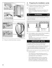
...;off the main water tap to the connecting pipe when pushing in the beam. q Install the connecting pipe. IMPORTANT NOTE ! Always observe the indicated gap dimensions to prevent damage to prevent damage caused by leaking water. q Attach the connecting pipe to the required length. q Saw the wooden beam (cross section min...
...;off the main water tap to the connecting pipe when pushing in the beam. q Install the connecting pipe. IMPORTANT NOTE ! Always observe the indicated gap dimensions to prevent damage to prevent damage caused by leaking water. q Attach the connecting pipe to the required length. q Saw the wooden beam (cross section min...

Installation Instructions
Page 27
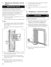
A mark is attached to the appliance base and is used as an alternative antiĆtip device according to comply with this dimension for height adjustment. When unscrewing the heightĆadjustable feet, proceed gradually: Always alternate between left and right, left and right, etc.. - Attaching the... lugs (top) to the top of the cavity q Unscrew the heightĆadjustable feet until the mark on the base has reached the indicated guide dimension (1¼" / 32 mm). i Note: - If using a wooden beam as a standard gage for the subsequent alignment of this mark at the front and rear ...
A mark is attached to the appliance base and is used as an alternative antiĆtip device according to comply with this dimension for height adjustment. When unscrewing the heightĆadjustable feet, proceed gradually: Always alternate between left and right, left and right, etc.. - Attaching the... lugs (top) to the top of the cavity q Unscrew the heightĆadjustable feet until the mark on the base has reached the indicated guide dimension (1¼" / 32 mm). i Note: - If using a wooden beam as a standard gage for the subsequent alignment of this mark at the front and rear ...

Installation Instructions
Page 36
... adjacent furniture (1.). q Clamp the finger guard under the brackets (2.). q Using a knife and steel ruler, shorten the finger guard to the finger guard. q Transfer the door dimensions to the required length. 36 Attaching the finger guard i The number of lower brackets depends on the finger guard must cover the entire height of...
... adjacent furniture (1.). q Clamp the finger guard under the brackets (2.). q Using a knife and steel ruler, shorten the finger guard to the finger guard. q Transfer the door dimensions to the required length. 36 Attaching the finger guard i The number of lower brackets depends on the finger guard must cover the entire height of...
Use & Care Manual
Page 7
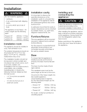
... rise above 110 °F (43 °C), otherwise malfunctions may have moved. The installation area must be checked by an electrician according to observe the specified dimensions of the installation cavity for a troubleĆfree installation of the appliance and for the subsequent general view of frost. During transit the oil in...
... rise above 110 °F (43 °C), otherwise malfunctions may have moved. The installation area must be checked by an electrician according to observe the specified dimensions of the installation cavity for a troubleĆfree installation of the appliance and for the subsequent general view of frost. During transit the oil in...