

Installation Instructions
Page 3
... 3 Tools 17 5. Optional accessories 17 3. Supplied accessories 17 2. Contents Before you Begin 5 Definitions 5 Important information 5 Installation options 6 Individual unit 6 SideĆbyĆSide 6 Individual appliances with partition 6 At the end of the kitchen units 6 Installation location 7 Installation room 7 Installation cavity 7 Furniture/fixtures 7 Base 7 Connecting the power 8 Additional grounding procedure 8 Grounding...
... 3 Tools 17 5. Optional accessories 17 3. Supplied accessories 17 2. Contents Before you Begin 5 Definitions 5 Important information 5 Installation options 6 Individual unit 6 SideĆbyĆSide 6 Individual appliances with partition 6 At the end of the kitchen units 6 Installation location 7 Installation room 7 Installation cavity 7 Furniture/fixtures 7 Base 7 Connecting the power 8 Additional grounding procedure 8 Grounding...
Installation Instructions
Page 4
... antiĆtip device 24 8. Preparing to the appliance 28 16. Attaching the appliance to the top of the appliance 18 3. Connecting the water to connect the water 24 9. Commissioning the Appliance 30 18. Loading the appliance door 32 20. Attaching and aligning the furniture door...Side installation 25 11. Attaching the covers 37 26. Checking the installation cavity 18 2.. Installing and aligning the appliance 26 13. Attaching the individual appliance to the furniture door 32 21. Adjusting the door opening angle 41 31. Removing the packaging 19 4. ...
... antiĆtip device 24 8. Preparing to the appliance 28 16. Attaching the appliance to the top of the appliance 18 3. Connecting the water to connect the water 24 9. Commissioning the Appliance 30 18. Loading the appliance door 32 20. Attaching and aligning the furniture door...Side installation 25 11. Attaching the covers 37 26. Checking the installation cavity 18 2.. Installing and aligning the appliance 26 13. Attaching the individual appliance to the furniture door 32 21. Adjusting the door opening angle 41 31. Removing the packaging 19 4. ...
Installation Instructions
Page 5
...most importantly, safe. e IMPORTANT Save these instructions completely and carefully. In the U.S.A., in full. Keep doors closed until the appliance is the responsibility of complying with the Consumer. e WARNING Use this warning. The installation should be carried out by licensed personnel... FOR PROPER INSTALLATION. Definitions d WARNING d WARNING - Before you Begin Read these instructions for its intended purpose. Unplug the appliance or switch off the fuse before cleaning or making repairs. - This indicates that death or serious injuries may occur as a...
...most importantly, safe. e IMPORTANT Save these instructions completely and carefully. In the U.S.A., in full. Keep doors closed until the appliance is the responsibility of complying with the Consumer. e WARNING Use this warning. The installation should be carried out by licensed personnel... FOR PROPER INSTALLATION. Definitions d WARNING d WARNING - Before you Begin Read these instructions for its intended purpose. Unplug the appliance or switch off the fuse before cleaning or making repairs. - This indicates that death or serious injuries may occur as a...
Installation Instructions
Page 6
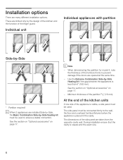
... the doors are installed SideĆbyĆSide, the Basic Combination SideĆby the design of the kitchen and the function of the appliance is square and the exact size. 6 Minimum thickness of the side panel are limited only by ĆSide Sealing kit must be used . These are... taken from the opposite cavity wall. SideĆby ĆSide Heating kit if the gap between the appliances is placed in the cavity. The side panel must be connected firmly to ensure a stable connection. At the end of the kitchen units If one...
... the doors are installed SideĆbyĆSide, the Basic Combination SideĆby the design of the kitchen and the function of the appliance is square and the exact size. 6 Minimum thickness of the side panel are limited only by ĆSide Sealing kit must be used . These are... taken from the opposite cavity wall. SideĆby ĆSide Heating kit if the gap between the appliances is placed in the cavity. The side panel must be connected firmly to ensure a stable connection. At the end of the kitchen units If one...

Installation Instructions
Page 7
...18" Wine unit 24" approx. 550 lbs / 245 kg approx. 694 lbs / 310 kg (* without Water Dispenser) Installation room The appliance should be exposed to the base or the wall by suitable means, e.g. outdoors, - If installation next to adjacent and overhead furniture/fixtures.... Furniture/fixtures The new appliance is very heavy ć for the subsequent general view of frost. The installation location should not drop below 55 °F (13...
...18" Wine unit 24" approx. 550 lbs / 245 kg approx. 694 lbs / 310 kg (* without Water Dispenser) Installation room The appliance should be exposed to the base or the wall by suitable means, e.g. outdoors, - If installation next to adjacent and overhead furniture/fixtures.... Furniture/fixtures The new appliance is very heavy ć for the subsequent general view of frost. The installation location should not drop below 55 °F (13...
Installation Instructions
Page 8
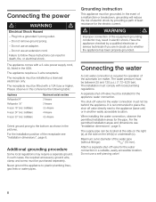
...adapter. - d WARNING d Electrical Shock Hazard - IceMaker) Maximum load at the side on the left (b) or underneath (c). Never ground the appliance to the appliance (base unit) or in the pictures. The receptacle must be located at the side on the right (a), at one time 2 Ampere 2... Ampere 3.5 Ampere 4 Ampere 4.5 Ampere Orient ground prong to whether the appliance has been properly grounded. IceMaker) Freezer 30" (incl. For the permitted installation areas and dimensions see "Installation dimensions", page 8. For the...
...adapter. - d WARNING d Electrical Shock Hazard - IceMaker) Maximum load at the side on the left (b) or underneath (c). Never ground the appliance to the appliance (base unit) or in the pictures. The receptacle must be located at the side on the right (a), at one time 2 Ampere 2... Ampere 3.5 Ampere 4 Ampere 4.5 Ampere Orient ground prong to whether the appliance has been properly grounded. IceMaker) Freezer 30" (incl. For the permitted installation areas and dimensions see "Installation dimensions", page 8. For the...
Installation Instructions
Page 9
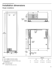
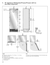
Single installation6. Side wall of niche, depending on kitchen design (see DESIGN GUIDE) D = 24" (610 mm) minimum NOTE: Cavity must be suare. Legend: A Area for installation of the water connection B Area for installation of the power connection D Opening depth of the cavity must be flush. Appliance 18" 24" 30" X 18" (457 mm) 24 (610 mm) 30" (762 mm) Y 9" (229 mm) 12" (305 mm) 15" (381 mm) 9 Installation dimensions5.
Single installation6. Side wall of niche, depending on kitchen design (see DESIGN GUIDE) D = 24" (610 mm) minimum NOTE: Cavity must be suare. Legend: A Area for installation of the water connection B Area for installation of the power connection D Opening depth of the cavity must be flush. Appliance 18" 24" 30" X 18" (457 mm) 24 (610 mm) 30" (762 mm) Y 9" (229 mm) 12" (305 mm) 15" (381 mm) 9 Installation dimensions5.
Installation Instructions
Page 10
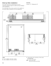
... suare. Example: Freezer 18" / Refrigerator 30" Legend: A Area for installation of the water connection B Area for the two appliances. SideĆbyĆSide installation The cavity dimensions indicated above for the respective appliance apply to a SideĆbyĆSide installation of the cavity widths indicated for installation of the power...
... suare. Example: Freezer 18" / Refrigerator 30" Legend: A Area for installation of the water connection B Area for the two appliances. SideĆbyĆSide installation The cavity dimensions indicated above for the respective appliance apply to a SideĆbyĆSide installation of the cavity widths indicated for installation of the power...

Installation Instructions
Page 12
d) This dimension may vary. b) Dimensions may vary depending on installation, panel thickness and kitchen hardware. 12 e) Unit dimensions Note: One design of door panel may vary. For further information about the different styles check the DESIGN GUIDE. c) Thickness of the wooden panel displayed. Appliance dimensions7. 1. 18" Appliance (Freezer/Freezer with Ice and Water dispenser) e) e) Front view (without door panel) Legend: a) Adjustment in levelling legs +13/8" (35 mm) / -1/2" (13 mm).
d) This dimension may vary. b) Dimensions may vary depending on installation, panel thickness and kitchen hardware. 12 e) Unit dimensions Note: One design of door panel may vary. For further information about the different styles check the DESIGN GUIDE. c) Thickness of the wooden panel displayed. Appliance dimensions7. 1. 18" Appliance (Freezer/Freezer with Ice and Water dispenser) e) e) Front view (without door panel) Legend: a) Adjustment in levelling legs +13/8" (35 mm) / -1/2" (13 mm).
Installation Instructions
Page 13
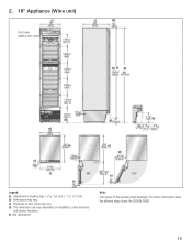
b) Dimensions may vary depending on installation, panel thickness and kitchen hardware. d) This dimension may vary. e) Unit dimensions Note: One design of door panel may vary. For further information about the different styles check the DESIGN GUIDE. 13 2. 18" Appliance (Wine unit) e) e) Front view (without door panel) Legend: a) Adjustment in levelling legs +13/8" (35 mm) / -1/2" (13 mm). c) Thickness of the wooden panel displayed.
b) Dimensions may vary depending on installation, panel thickness and kitchen hardware. d) This dimension may vary. e) Unit dimensions Note: One design of door panel may vary. For further information about the different styles check the DESIGN GUIDE. 13 2. 18" Appliance (Wine unit) e) e) Front view (without door panel) Legend: a) Adjustment in levelling legs +13/8" (35 mm) / -1/2" (13 mm). c) Thickness of the wooden panel displayed.
Installation Instructions
Page 14
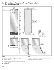
b) Dimensions may vary depending on installation, panel thickness and kitchen hardware. e) Unit dimensions 14 Note: One design of door panel may vary. For further information about the different styles check the DESIGN GUIDE. d) This dimension may vary. c) Thickness of the wooden panel displayed. 3. 24" Appliance (Refrigerator/Freezer/Freezer with Ice and Water dispenser) e) e) Front view (without door panel) Legend: a) Adjustment in levelling legs +13/8" (35 mm) / -1/2" (13 mm).
b) Dimensions may vary depending on installation, panel thickness and kitchen hardware. e) Unit dimensions 14 Note: One design of door panel may vary. For further information about the different styles check the DESIGN GUIDE. d) This dimension may vary. c) Thickness of the wooden panel displayed. 3. 24" Appliance (Refrigerator/Freezer/Freezer with Ice and Water dispenser) e) e) Front view (without door panel) Legend: a) Adjustment in levelling legs +13/8" (35 mm) / -1/2" (13 mm).

Installation Instructions
Page 15
c) Thickness of the wooden panel displayed. d) This dimension may vary. b) Dimensions may vary. 4. 24" Appliance (Wine unit) e) e) Front view (without door panel) Legend: a) Adjustment in levelling legs +13/8" (35 mm) / -1/2" (13 mm). e) Unit dimensions Note: One design of door panel may vary depending on installation, panel thickness and kitchen hardware. For further information about the different styles check the DESIGN GUIDE. 15
c) Thickness of the wooden panel displayed. d) This dimension may vary. b) Dimensions may vary. 4. 24" Appliance (Wine unit) e) e) Front view (without door panel) Legend: a) Adjustment in levelling legs +13/8" (35 mm) / -1/2" (13 mm). e) Unit dimensions Note: One design of door panel may vary depending on installation, panel thickness and kitchen hardware. For further information about the different styles check the DESIGN GUIDE. 15
Installation Instructions
Page 16
c) Thickness of the wooden panel displayed. d) This dimension may vary. b) Dimensions may vary. e) Unit dimensions 16 Note: One design of door panel may vary depending on installation, panel thickness and kitchen hardware. 5. 30" Appliance (Refrigerator/Freezer/Freezer with Ice and Water dispenser) e) e) Front view (without door panel) Legend: a) Adjustment in levelling legs +13/8" (35 mm) / -1/2" (13 mm). For further information about the different styles check the DESIGN GUIDE.
c) Thickness of the wooden panel displayed. d) This dimension may vary. b) Dimensions may vary. e) Unit dimensions 16 Note: One design of door panel may vary depending on installation, panel thickness and kitchen hardware. 5. 30" Appliance (Refrigerator/Freezer/Freezer with Ice and Water dispenser) e) e) Front view (without door panel) Legend: a) Adjustment in levelling legs +13/8" (35 mm) / -1/2" (13 mm). For further information about the different styles check the DESIGN GUIDE.
Installation Instructions
Page 17
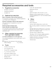
...from damage (e.g. i Maximum outer diameter of two furniture doors. Square - MarkingĆout level, length at least 4' (1.2 m) for individual appliances or 7' (2.0 m) for drilling holes in different sizes - Stepladder - Hammer drill for SideĆbyĆSide installation 5. Wooden beam ...(1.5 mm)), suitable material to protect the floor from specialist outlets Ice maker installation kit ¼" OD copper line For connecting appliances which require water, e.g. Suitable material for standard height furniture doors without fittings): 13/32" (10 mm). - Adhesive tape ...
...from damage (e.g. i Maximum outer diameter of two furniture doors. Square - MarkingĆout level, length at least 4' (1.2 m) for individual appliances or 7' (2.0 m) for drilling holes in different sizes - Stepladder - Hammer drill for SideĆbyĆSide installation 5. Wooden beam ...(1.5 mm)), suitable material to protect the floor from specialist outlets Ice maker installation kit ¼" OD copper line For connecting appliances which require water, e.g. Suitable material for standard height furniture doors without fittings): 13/32" (10 mm). - Adhesive tape ...
Installation Instructions
Page 18
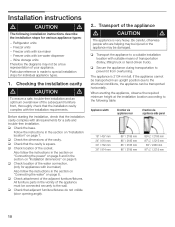
... diagrams may be transported horizontally. q Check attachment of the cavity. Transport of the water connection. (only for individual appliance types. 1. The appliance is very heavy. Refrigerator units - q Check the dimensions of the adjacent furniture/fixtures. q Check that the installation cavity...of the socket. q Check that the installation cavity complies with ice maker - Installation instructions d CAUTION d The following table: Appliance width Erection via appliance rear Erection via appliance side panel 18" / 457 mm 24" / 610 mm 30" / 762 mm 36" / 914 mm 86" / ...
... diagrams may be transported horizontally. q Check attachment of the cavity. Transport of the water connection. (only for individual appliance types. 1. The appliance is very heavy. Refrigerator units - q Check the dimensions of the adjacent furniture/fixtures. q Check that the installation cavity...of the socket. q Check that the installation cavity complies with ice maker - Installation instructions d CAUTION d The following table: Appliance width Erection via appliance rear Erection via appliance side panel 18" / 457 mm 24" / 610 mm 30" / 762 mm 36" / 914 mm 86" / ...
Installation Instructions
Page 19
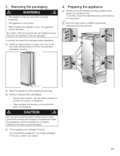
... during installation: q Attach a residual piece of appliance. - Use the cutter securely to the floor with a hand truck securely. Do not install the appliance if it is visibly damaged. When opening the appliance door, the appliance may be damaged. To do this, loosen the..., etc. Take supplied accessories out of protection parts of the intended installation location. 4. q Move the appliance with adhesive tape in doubt, contact your dealer. 19 The appliance may get lost. d CAUTION d Do not remove transportation safety devices which attach the furniture fronts. q...
... during installation: q Attach a residual piece of appliance. - Use the cutter securely to the floor with a hand truck securely. Do not install the appliance if it is visibly damaged. When opening the appliance door, the appliance may be damaged. To do this, loosen the..., etc. Take supplied accessories out of protection parts of the intended installation location. 4. q Move the appliance with adhesive tape in doubt, contact your dealer. 19 The appliance may get lost. d CAUTION d Do not remove transportation safety devices which attach the furniture fronts. q...
Installation Instructions
Page 21
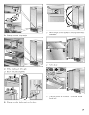
q Change over the fixation parts on the door. q Span the spring on the appliance. Tighten the screw from 0 to I. 21 q Fit the plastic part of the grill. q Fix the hinges on the hinge. q Fix the door. q Mount the grill completely. q Change over the hinge angle. Change the hinges crosswise!
q Change over the fixation parts on the door. q Span the spring on the appliance. Tighten the screw from 0 to I. 21 q Fit the plastic part of the grill. q Fix the hinges on the hinge. q Fix the door. q Mount the grill completely. q Change over the hinge angle. Change the hinges crosswise!
Installation Instructions
Page 22
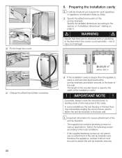
.... The length of the installation cavity! ! Select the fastening screws according to the width of the wooden beam is deeper than the appliance, place a solid wooden beam behind the antiĆtipĆbrackets and attach securely to the section on Installation dimensions" starting on... antiĆtipĆbrackets to the back wall. Specify the detailed dimensions according to the base or the wall. i Important information for each appliance or appliance combination (SideĆbyĆSide). q Fix the hinge box cover. 6. q Change the attachment plates crosswise. 22 (609,6-647,7) q ...
.... The length of the installation cavity! ! Select the fastening screws according to the width of the wooden beam is deeper than the appliance, place a solid wooden beam behind the antiĆtipĆbrackets and attach securely to the section on Installation dimensions" starting on... antiĆtipĆbrackets to the back wall. Specify the detailed dimensions according to the base or the wall. i Important information for each appliance or appliance combination (SideĆbyĆSide). q Fix the hinge box cover. 6. q Change the attachment plates crosswise. 22 (609,6-647,7) q ...
Installation Instructions
Page 24
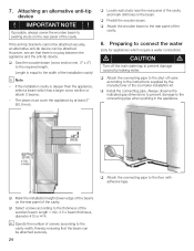
... x 4") to the floor with adhesive tape. Preparing to the thickness of the cavity. 8. q Select screws according to connect the water (only for appliances which has a larger cross section or attach 2 beams. - If the antiĆtip brackets cannot be attached securely, an alternative antiĆtip device ...cavity. q Mark the installation height (lower edge of the beam) on the rear panel of the cavity and mark drill holes in the appliance. If possible, always screw the wooden beam to prevent damage caused by at least 2" (50.8 mm). If the installation cavity is ...
... x 4") to the floor with adhesive tape. Preparing to the thickness of the cavity. 8. q Select screws according to connect the water (only for appliances which has a larger cross section or attach 2 beams. - If the antiĆtip brackets cannot be attached securely, an alternative antiĆtip device ...cavity. q Mark the installation height (lower edge of the beam) on the rear panel of the cavity and mark drill holes in the appliance. If possible, always screw the wooden beam to prevent damage caused by at least 2" (50.8 mm). If the installation cavity is ...

Installation Instructions
Page 25
... the installation cavity d CAUTION d Caution when pushing the appliance into the installation cavity. 25 i When the floor or the appliance is intended, now connect the two appliances together. See the Installation Manual for the SideĆby Ćside installation is tilted in comparison to the floor. q To protect the corners of ... ĆSide kits. Do not damage the water pipe or power cord attached to the installation cavity adjust height adjustable wheels before you move the appliance into the installation cavity. 9.
... the installation cavity d CAUTION d Caution when pushing the appliance into the installation cavity. 25 i When the floor or the appliance is intended, now connect the two appliances together. See the Installation Manual for the SideĆby Ćside installation is tilted in comparison to the floor. q To protect the corners of ... ĆSide kits. Do not damage the water pipe or power cord attached to the installation cavity adjust height adjustable wheels before you move the appliance into the installation cavity. 9.