Operating Instructions
Page 2
... dust or fumes. Do not operate power tools in power tools that have the switch on . Water entering a power tool will reduce personal injuries. A moment of electric shock. Use safety equipment. Failure to your finger on the switch or plugging in explosive atmospheres, such as dust mask, non-skid safety shoes, hard hat, or hearing protection used . When operating a power tool outdoors, use AC only rated tools with your mains-operated (corded) power tool or battery-operated (cordless) power tool...
... dust or fumes. Do not operate power tools in power tools that have the switch on . Water entering a power tool will reduce personal injuries. A moment of electric shock. Use safety equipment. Failure to your finger on the switch or plugging in explosive atmospheres, such as dust mask, non-skid safety shoes, hard hat, or hearing protection used . When operating a power tool outdoors, use AC only rated tools with your mains-operated (corded) power tool or battery-operated (cordless) power tool...

Operating Instructions
Page 3
... switch on and off position before inserting battery pack. Use the power tool, accessories and tool bits etc., in the manner intended for the particular type of parts and any adjustments, changing accessories, or storing power tools. Use clamps or other small metal objects that may lead to be repaired. Holding the work to loss of the power tool is suitable for operations different from oil and grease. Battery tool use . Use battery tools only with the charger specified by a qualified repair...
... switch on and off position before inserting battery pack. Use the power tool, accessories and tool bits etc., in the manner intended for the particular type of parts and any adjustments, changing accessories, or storing power tools. Use clamps or other small metal objects that may lead to be repaired. Holding the work to loss of the power tool is suitable for operations different from oil and grease. Battery tool use . Use battery tools only with the charger specified by a qualified repair...
Operating Instructions
Page 4
... the blade head housing and the blade locking screws are specially designed to these chemicals: work in any assembly, adjustments or changing accessories. The blades are nails, either remove or set them well below intended finished surface. Do not substitute any objects into charger. Check the workpiece for Cordless Planers Secure the material being planed. Contact with your product or direct replacement as listed in the catalog or this type of work...
... the blade head housing and the blade locking screws are specially designed to these chemicals: work in any assembly, adjustments or changing accessories. The blades are nails, either remove or set them well below intended finished surface. Do not substitute any objects into charger. Check the workpiece for Cordless Planers Secure the material being planed. Contact with your product or direct replacement as listed in the catalog or this type of work...

Operating Instructions
Page 5
... below +105 degrees F (41 degrees C). The charger and battery pack heat during charging. Use of fire, electric shock or injury to disassemble the battery or remove any component projecting from metal objects. WARNING When batteries are not in a risk of an attachment not recommended or sold by Bosch may result in tool or charger, keep them with skin and eyes...
... below +105 degrees F (41 degrees C). The charger and battery pack heat during charging. Use of fire, electric shock or injury to disassemble the battery or remove any component projecting from metal objects. WARNING When batteries are not in a risk of an attachment not recommended or sold by Bosch may result in tool or charger, keep them with skin and eyes...
Operating Instructions
Page 6
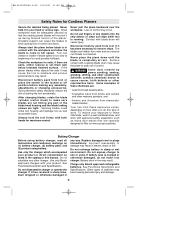
... that this tool is increasing from 0 setting Arrow Action in the direction of arrow Alternating current Type or a characteristic of current Direct current Type or a characteristic of current Alternating or direct current Type or a characteristic of drill bits, grinding wheels, etc. n0 .../min No load speed Rotational speed, at no load Revolutions or reciprocation per minute Revolutions, strokes, surface speed, orbits etc. Higher number means greater speed 0 Infinitely...
... that this tool is increasing from 0 setting Arrow Action in the direction of arrow Alternating current Type or a characteristic of current Direct current Type or a characteristic of current Alternating or direct current Type or a characteristic of drill bits, grinding wheels, etc. n0 .../min No load speed Rotational speed, at no load Revolutions or reciprocation per minute Revolutions, strokes, surface speed, orbits etc. Higher number means greater speed 0 Infinitely...
Operating Instructions
Page 7
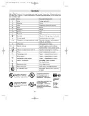
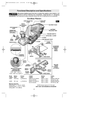
... LEVER "LOCK-OFF" BUTTON FIG. 1 CHIP EXHAUST PORT RABBETING DEPTH STOP (OPTIONAL) DEPTH ADJUSTMENT KNOB WING KNOB FRONT SHOE BATTERY PACK BATTERY RELEASE TABS SCREW TRIGGER SWITCH DRIVE BELT COVER SCREW CHIP EXHAUST PORT GUIDE BRACKET STANDARD PARALLEL WIDTH GUIDE FENCE CHAMFER V-GROOVE FENCE WING KNOB DEPTH SCALE WING KNOB THE CUTTING DEPTH CHOICES ARE APPROXIMATELY 1/16", 3/64", 1mm (•), 1/32", 1/64", & 1/128" (•) GUIDE BRACKET PIVOT FENCE ROUND KNOB WIDTH SCALE WING KNOB DELUXE ANGLE FENCE (OPTIONAL) Model Voltage number rating 53514 14.4 V No load speed...
... LEVER "LOCK-OFF" BUTTON FIG. 1 CHIP EXHAUST PORT RABBETING DEPTH STOP (OPTIONAL) DEPTH ADJUSTMENT KNOB WING KNOB FRONT SHOE BATTERY PACK BATTERY RELEASE TABS SCREW TRIGGER SWITCH DRIVE BELT COVER SCREW CHIP EXHAUST PORT GUIDE BRACKET STANDARD PARALLEL WIDTH GUIDE FENCE CHAMFER V-GROOVE FENCE WING KNOB DEPTH SCALE WING KNOB THE CUTTING DEPTH CHOICES ARE APPROXIMATELY 1/16", 3/64", 1mm (•), 1/32", 1/64", & 1/128" (•) GUIDE BRACKET PIVOT FENCE ROUND KNOB WIDTH SCALE WING KNOB DELUXE ANGLE FENCE (OPTIONAL) Model Voltage number rating 53514 14.4 V No load speed...

Operating Instructions
Page 8
... to remove, you may then tighten the clamping screws which may be used blades of any kind. CLAMPING SCREW CUTTER DRUM FIG. 5 BLADE WRENCH Make sure the blade sits correctly in the holder groove of the exhaust port. BM 2610925944 6-05 6/10/05 11:50 AM Page 8 Assembly CHIP EXTRACTION The planer comes with two chip exhaust ports, which secure the blade and your work environment...
... to remove, you may then tighten the clamping screws which may be used blades of any kind. CLAMPING SCREW CUTTER DRUM FIG. 5 BLADE WRENCH Make sure the blade sits correctly in the holder groove of the exhaust port. BM 2610925944 6-05 6/10/05 11:50 AM Page 8 Assembly CHIP EXTRACTION The planer comes with two chip exhaust ports, which secure the blade and your work environment...
Operating Instructions
Page 9
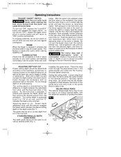
... fixed rear shoe of an inch. Setting the cutting width: Loosen wing knob and slide the fence along the guide bracket to the tool if the motor labors. The cutting depth is graduated from 0 to obtain a good surface finish. ! BM 2610925944 6-05 6/10/05 11:50 AM Page 9 Operating Instructions TRIGGER "ON/OFF" SWITCH ! Reduce the pressure (feed rate) or depth of an inch, and the "0" indicates the blade is spring loaded...
... fixed rear shoe of an inch. Setting the cutting width: Loosen wing knob and slide the fence along the guide bracket to the tool if the motor labors. The cutting depth is graduated from 0 to obtain a good surface finish. ! BM 2610925944 6-05 6/10/05 11:50 AM Page 9 Operating Instructions TRIGGER "ON/OFF" SWITCH ! Reduce the pressure (feed rate) or depth of an inch, and the "0" indicates the blade is spring loaded...

Operating Instructions
Page 10
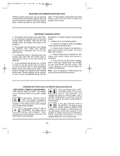
.... 8 DRIVE BELT COVER SCREW -10- Securely tighten wing knob (Fig. 1). The maximum rabbeting depth is controlled by repetitive cutting until the rabbeting depth guide contacts the workpiece. Cut and remove the worn drive belt. Setting the cutting width: Loosen wing knob and using the deluxe angle/width fence (Fig. 7). Before installing the new drive belt, clean both pulleys thoroughly. BM 2610925944 6-05 6/10/05 11:50 AM Page 10 on the rabbeting depth stop accessory...
.... 8 DRIVE BELT COVER SCREW -10- Securely tighten wing knob (Fig. 1). The maximum rabbeting depth is controlled by repetitive cutting until the rabbeting depth guide contacts the workpiece. Cut and remove the worn drive belt. Setting the cutting width: Loosen wing knob and using the deluxe angle/width fence (Fig. 7). Before installing the new drive belt, clean both pulleys thoroughly. BM 2610925944 6-05 6/10/05 11:50 AM Page 10 on the rabbeting depth stop accessory...
Operating Instructions
Page 11
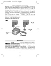
... dirt. The charger will switch automatically to fast-charging. To insert battery, align battery and slide battery pack into position. However, after the first few charge cycles. a month or more) of non-use of the charger or battery pack are turned off " when lights are contaminated. If battery does not charge properly: a. b. See "Tools, Electric" in some other electrical device. If the green indicator light is "ON...
... dirt. The charger will switch automatically to fast-charging. To insert battery, align battery and slide battery pack into position. However, after the first few charge cycles. a month or more) of non-use of the charger or battery pack are turned off " when lights are contaminated. If battery does not charge properly: a. b. See "Tools, Electric" in some other electrical device. If the green indicator light is "ON...
Operating Instructions
Page 12
... the indicator lights are contaminated. Before inserting battery pack, remove protective cap, then insert battery pack into the tool. If the green indicator light is "ON", the charger is plugged in these operating instructions or those supplied with your standard power outlet. BM 2610925944 6-05 6/10/05 11:50 AM Page 12 Plug charger cord into your tool or battery pack. Fastcharging will stop when the battery pack...
... the indicator lights are contaminated. Before inserting battery pack, remove protective cap, then insert battery pack into the tool. If the green indicator light is "ON", the charger is plugged in these operating instructions or those supplied with your standard power outlet. BM 2610925944 6-05 6/10/05 11:50 AM Page 12 Plug charger cord into your tool or battery pack. Fastcharging will stop when the battery pack...

Operating Instructions
Page 13
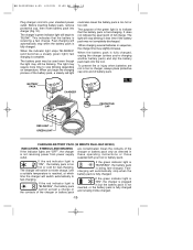
...:50 AM Page 13 Plug charger cord into charger (Fig. 11). Before inserting battery pack, remove protective cap, then insert battery pack into your standard power outlet. The battery pack may be used even though the light may require more time to "BLINK". The light may still be blinking. BATTERY PACK FIG. 11 PROTECTIVE CAP CHARGER RED LIGHT GREEN LIGHT CHARGING BATTERY PACK (1 HOUR CHARGER) INDICATORS, SYMBOLS AND MEANING...
...:50 AM Page 13 Plug charger cord into charger (Fig. 11). Before inserting battery pack, remove protective cap, then insert battery pack into your standard power outlet. The battery pack may be used even though the light may require more time to "BLINK". The light may still be blinking. BATTERY PACK FIG. 11 PROTECTIVE CAP CHARGER RED LIGHT GREEN LIGHT CHARGING BATTERY PACK (1 HOUR CHARGER) INDICATORS, SYMBOLS AND MEANING...
Operating Instructions
Page 14
... the battery is When the battery pack is fully charged, receiving a fast charge. cap onto end of full charge. It does not protective cap, then insert battery pack into the tool handle. pack back into indicate the exact point of battery pack. Before inserting battery pack, remove battery pack is complete. SERVICEMEN: Disconnect tool and/or charger from power source before servicing. WARNING NO USER SERVICEABLE PARTS INSIDE...
... the battery is When the battery pack is fully charged, receiving a fast charge. cap onto end of full charge. It does not protective cap, then insert battery pack into the tool handle. pack back into indicate the exact point of battery pack. Before inserting battery pack, remove battery pack is complete. SERVICEMEN: Disconnect tool and/or charger from power source before servicing. WARNING NO USER SERVICEABLE PARTS INSIDE...
Operating Instructions
Page 15
... equipment) (**= optional accessories) * Standard parallel width guide fence ** Deluxe angle fence ** Rabbeting depth stop * Blade wrench 2.5mm * Carbide reversible blades (2) * Vacuum connector ** Vacuum hose ** Chip bag ** 15 minute charger ** 30 minute charger (single bay) ** 30 minute charger (dual bay) ** 1 hour charger -15- TOOL LUBRICATION Your Bosch tool has been properly lubricated and is capable of the motor, we recommend it be cleaned most effectively with compressed air. Battery packs last longer...
... equipment) (**= optional accessories) * Standard parallel width guide fence ** Deluxe angle fence ** Rabbeting depth stop * Blade wrench 2.5mm * Carbide reversible blades (2) * Vacuum connector ** Vacuum hose ** Chip bag ** 15 minute charger ** 30 minute charger (single bay) ** 30 minute charger (dual bay) ** 1 hour charger -15- TOOL LUBRICATION Your Bosch tool has been properly lubricated and is capable of the motor, we recommend it be cleaned most effectively with compressed air. Battery packs last longer...
Parts List
Page 1
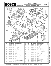
... 74 846 2 607 200 451 Switch 15 48 851 2 608 635 405 Blade (PA1202) 94 852 2 603 111 001 Blade Holder 9 9 853 2 603 400 016 Set Screw {2} 89 9 + = Not Illustrated * = As Required F/C = Failure Code AW = Refer to AW Labor Time Chart S-B Power Tool Company Chicago IL 60646-5999 Part Number Description {Qty.} F/C Pos. September 2002 INDUSTRIAL 14.4V PLANER Model 0601595460 53514 20 1 37 49...
... 74 846 2 607 200 451 Switch 15 48 851 2 608 635 405 Blade (PA1202) 94 852 2 603 111 001 Blade Holder 9 9 853 2 603 400 016 Set Screw {2} 89 9 + = Not Illustrated * = As Required F/C = Failure Code AW = Refer to AW Labor Time Chart S-B Power Tool Company Chicago IL 60646-5999 Part Number Description {Qty.} F/C Pos. September 2002 INDUSTRIAL 14.4V PLANER Model 0601595460 53514 20 1 37 49...


