
Operating Instructions
Page 3
...follow Maintenance Instructions may create a risk of the planer. Never hold it in a risk of cut if blade is dangerous and must be suitable for nails, if there are hidden from the power source before using. If the planer blades strike objects like nails it is too slow ...at the rate for your model. Spinning blades could result in your application. Any alteration or modification is "OFF". The blades are nails, either remove or ...
...follow Maintenance Instructions may create a risk of the planer. Never hold it in a risk of cut if blade is dangerous and must be suitable for nails, if there are hidden from the power source before using. If the planer blades strike objects like nails it is too slow ...at the rate for your model. Spinning blades could result in your application. Any alteration or modification is "OFF". The blades are nails, either remove or ...
Operating Instructions
Page 7
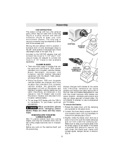
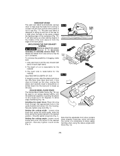
...your work on the machine itself, pull the power plug. FIG. 2 CHIP BAG EXHAUST PORTS FIG. 3 VACUUM CONNECTOR (OPTIONAL) Always changes both blades at the same time. PLANER BLADES • There are sharp and may clean the blade and clamp with the 1594 it is not necessary... An adapter to connect the hood to 2-1/2" hoses is gummed and difficult to sharpen or use with the Bosch 1594 planer; To remove the blades: 1. WARNING Wear protective gloves when changing planer blades. Do not attempt to remove, you may cause injury. Make sure to 1-1/4" and 1-1/2" vacuum hoses. ...
...your work on the machine itself, pull the power plug. FIG. 2 CHIP BAG EXHAUST PORTS FIG. 3 VACUUM CONNECTOR (OPTIONAL) Always changes both blades at the same time. PLANER BLADES • There are sharp and may clean the blade and clamp with the 1594 it is not necessary... An adapter to connect the hood to 2-1/2" hoses is gummed and difficult to sharpen or use with the Bosch 1594 planer; To remove the blades: 1. WARNING Wear protective gloves when changing planer blades. Do not attempt to remove, you may cause injury. Make sure to 1-1/4" and 1-1/2" vacuum hoses. ...
Operating Instructions
Page 8
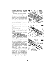
... screws and clean all surfaces with the ridge of the blade holder. (This will not touch against the sloping part of the blade holder and carefully slide the blade onto the blade holder, as shown in Figure 4, and your planer is ready for use. To ensure proper operation and an... a block of wood push the TC blade back towards the blade holder so that the inner side of the blade with mineral spirits; Under normal circumstances, the position of the retainer on top of the blade is best performed by a Bosch Factory Service or Bosch Authorized Service Center. INSTALLING AND ADJUSTING MINI...
... screws and clean all surfaces with the ridge of the blade holder. (This will not touch against the sloping part of the blade holder and carefully slide the blade onto the blade holder, as shown in Figure 4, and your planer is ready for use. To ensure proper operation and an... a block of wood push the TC blade back towards the blade holder so that the inner side of the blade with mineral spirits; Under normal circumstances, the position of the retainer on top of the blade is best performed by a Bosch Factory Service or Bosch Authorized Service Center. INSTALLING AND ADJUSTING MINI...

Operating Instructions
Page 9
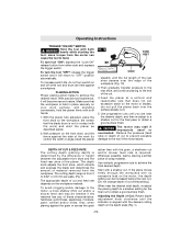
... leveled before installation using the correct tightening sequence (1,2,3). (Fig. 4) 4. Procedure: 1. Rotate the blade drum until the clamping jaw is parallel to the planer shoe. 2. Rotate the blade drum until the clamping jaw is parallel to the planer shoe. 2. Slightly rotate the blade drum and use a piece of wood to keep your fingers away from the...
... leveled before installation using the correct tightening sequence (1,2,3). (Fig. 4) 4. Procedure: 1. Rotate the blade drum until the clamping jaw is parallel to the planer shoe. 2. Rotate the blade drum until the clamping jaw is parallel to the planer shoe. 2. Slightly rotate the blade drum and use a piece of wood to keep your fingers away from the...
Operating Instructions
Page 11
...The cutting depth (planing depth) is held against a workpiece. To increase switch life, do not pull the planer back over the edge of scrap material. Make sure that the blade drum is required. Use progressive cuts until you are held in height between the adjustable front shoe and the fixed... from either side and squeeze the trigger switch. The depth knob adjusts the front shoe, which retracts and exposes the blade and determines the amount of the planer. Whenever possible, test by the difference in place securely on and off while tool and drum are near the desired ...
...The cutting depth (planing depth) is held against a workpiece. To increase switch life, do not pull the planer back over the edge of scrap material. Make sure that the blade drum is required. Use progressive cuts until you are held in height between the adjustable front shoe and the fixed... from either side and squeeze the trigger switch. The depth knob adjusts the front shoe, which retracts and exposes the blade and determines the amount of the planer. Whenever possible, test by the difference in place securely on and off while tool and drum are near the desired ...
Operating Instructions
Page 12
...(See FEED RATE & DEPTH OF CUT) If clogging occurs, stop the planer and move the chip eject lever back and forth. To minimize the possibility of clogging, make sure: 1. UNCLOGGING THE CHIP EXHAUST SYSTEM ! WARNING Remove plug from power source if it itself when the back of the plane crosses the...widths, with the work piece). PARK REST STAND The park rest stand automatically springs down to help keep the blade from coming in contact with the additional capability of guiding the planer on any angle up to 45 degrees, to allow easier handling when using the width scale, slide the ...
...(See FEED RATE & DEPTH OF CUT) If clogging occurs, stop the planer and move the chip eject lever back and forth. To minimize the possibility of clogging, make sure: 1. UNCLOGGING THE CHIP EXHAUST SYSTEM ! WARNING Remove plug from power source if it itself when the back of the plane crosses the...widths, with the work piece). PARK REST STAND The park rest stand automatically springs down to help keep the blade from coming in contact with the additional capability of guiding the planer on any angle up to 45 degrees, to allow easier handling when using the width scale, slide the ...
Parts Diagram
Page 2
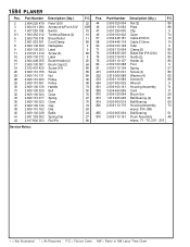
... 10 89 58 2 604 448 118 Cable 213mm 10 9 60 2 609 100 148 Tube 9 9 71 2 609 110 064 Clamp {2} 80 89 74 2 608 635 405 Blade Set (PA1202) 94 9 75 2 602 316 001 Guide {2} 80 25 76 2 609 110 107 Holder {2} 80 64 80 2 609 100 088 Foot 9 89 81 2 609... 110 161 Drum Assembly 48 66 w/pos. 71 - 76, 201 - 203 + = Not Illustrated * = As Required F/C = Failure Code AW = Refer to AW Labor Time Chart 1594 PLANER Pos. 2 3 4 5/1 6 7 8 9 11 15 16 17 19 20 26 28 29 30 31 32 33 35 37 38 40 41 43 Part Number 2 604 220 479...
... 10 89 58 2 604 448 118 Cable 213mm 10 9 60 2 609 100 148 Tube 9 9 71 2 609 110 064 Clamp {2} 80 89 74 2 608 635 405 Blade Set (PA1202) 94 9 75 2 602 316 001 Guide {2} 80 25 76 2 609 110 107 Holder {2} 80 64 80 2 609 100 088 Foot 9 89 81 2 609... 110 161 Drum Assembly 48 66 w/pos. 71 - 76, 201 - 203 + = Not Illustrated * = As Required F/C = Failure Code AW = Refer to AW Labor Time Chart 1594 PLANER Pos. 2 3 4 5/1 6 7 8 9 11 15 16 17 19 20 26 28 29 30 31 32 33 35 37 38 40 41 43 Part Number 2 604 220 479...


