Operating Instructions
Page 2
... INSTRUCTIONS Work Area Keep your tool. Electrical Safety Double Insulated tools are equipped with a DC power supply. Do not abuse the cord. When operating a power tool outside, use "AC only" rated tools with a polarized plug (one way. Personal Safety Stay alert, watch what you to install a polarized outlet. Avoid accidental starting. A wrench or a key that have the switch "ON" invites accidents. Failure to rain or wet conditions. Do not operate power tools...
... INSTRUCTIONS Work Area Keep your tool. Electrical Safety Double Insulated tools are equipped with a DC power supply. Do not abuse the cord. When operating a power tool outside, use "AC only" rated tools with a polarized plug (one way. Personal Safety Stay alert, watch what you to install a polarized outlet. Avoid accidental starting. A wrench or a key that have the switch "ON" invites accidents. Failure to rain or wet conditions. Do not operate power tools...
Operating Instructions
Page 3
... gasoline, carbon tetrachloride, ammonia, etc. Service or maintenance performed by poorly maintained tools. Safety Rules for your model. If the planer blades strike objects like nails it is too slow at the rate for your hand or across legs. Unstable support can vibrate or chatter if blade speed is designed. Do not use only identical replacement parts. Never leave the trigger locked "ON". When servicing a tool, use tool if switch does not turn it...
... gasoline, carbon tetrachloride, ammonia, etc. Service or maintenance performed by poorly maintained tools. Safety Rules for your model. If the planer blades strike objects like nails it is too slow at the rate for your hand or across legs. Unstable support can vibrate or chatter if blade speed is designed. Do not use only identical replacement parts. Never leave the trigger locked "ON". When servicing a tool, use tool if switch does not turn it...

Operating Instructions
Page 4
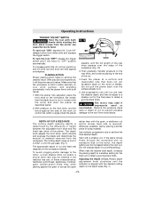
... ejector or clean out chips while tool is completely at rest. Sharp blades must be cut if blade is contacted. Some examples of these exposures varies, depending on how often you may occur. The blades are hidden from these chemicals are specially designed to remove chips. WARNING Some dust created by power sanding, sawing, grinding, drilling, and other construction activities contains...
... ejector or clean out chips while tool is completely at rest. Sharp blades must be cut if blade is contacted. Some examples of these exposures varies, depending on how often you may occur. The blades are hidden from these chemicals are specially designed to remove chips. WARNING Some dust created by power sanding, sawing, grinding, drilling, and other construction activities contains...
Operating Instructions
Page 5
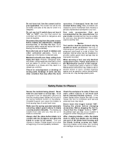
... Minutes Time s Seconds Time Diameter Size of current Class II construction Designates Double Insulated Construction tools. Higher number means greater speed 0 Infinitely variable selector with off Speed is increasing from 0 setting Arrow Action in the direction of arrow Alternating current Type or a characteristic of current Direct current Type or a characteristic of current Alternating or direct current Type or a characteristic of drill bits, grinding wheels, etc.
... Minutes Time s Seconds Time Diameter Size of current Class II construction Designates Double Insulated Construction tools. Higher number means greater speed 0 Infinitely variable selector with off Speed is increasing from 0 setting Arrow Action in the direction of arrow Alternating current Type or a characteristic of current Direct current Type or a characteristic of current Alternating or direct current Type or a characteristic of drill bits, grinding wheels, etc.
Operating Instructions
Page 6
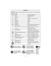
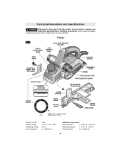
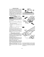
Planer FIG. 1 DEPTH ADJUSTMENT KNOB "LOCK-OFF" RELEASE BUTTON CHIP EXHAUST PORT WING KNOB TRIGGER SWITCH RABBETING DEPTH STOP (OPTIONAL) FRONT SHOE CHAMFER V-GROOVES DEPTH SCALE GUIDE BRACKET PIVOT FENCE ROUND KNOB DRIVE BELT COVER SCREW CHIP EXHAUST PORT PORT SELECTOR LEVER DELUXE BEVEL GUIDE FENCE WIDTH SCALE WING KNOB Note: Each unlabeled mark represents 0.5 mm. Model number Voltage rating Amperage rating No load speed 1594 120 V 50 - 60Hz 6.5 A n0 16,500/min Maximum Capacities Planing depth 0 - 3/32" (0 - 2.6mm) Rabbeting...
Planer FIG. 1 DEPTH ADJUSTMENT KNOB "LOCK-OFF" RELEASE BUTTON CHIP EXHAUST PORT WING KNOB TRIGGER SWITCH RABBETING DEPTH STOP (OPTIONAL) FRONT SHOE CHAMFER V-GROOVES DEPTH SCALE GUIDE BRACKET PIVOT FENCE ROUND KNOB DRIVE BELT COVER SCREW CHIP EXHAUST PORT PORT SELECTOR LEVER DELUXE BEVEL GUIDE FENCE WIDTH SCALE WING KNOB Note: Each unlabeled mark represents 0.5 mm. Model number Voltage rating Amperage rating No load speed 1594 120 V 50 - 60Hz 6.5 A n0 16,500/min Maximum Capacities Planing depth 0 - 3/32" (0 - 2.6mm) Rabbeting...
Operating Instructions
Page 7
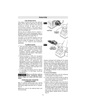
... (Fig.3) to keep your work on the machine itself, pull the power plug. Henceforth, all references in blade holder. Loosen the three clamp screws by about one of blades that will connect the hood to 1-1/4" and 1-1/2" vacuum hoses. Edges are three types of the cutting edges becomes dull or chipped. (Fig. 6) Before any TC blades. Moving the port selector lever to position 1 (towards front...
... (Fig.3) to keep your work on the machine itself, pull the power plug. Henceforth, all references in blade holder. Loosen the three clamp screws by about one of blades that will connect the hood to 1-1/4" and 1-1/2" vacuum hoses. Edges are three types of the cutting edges becomes dull or chipped. (Fig. 6) Before any TC blades. Moving the port selector lever to position 1 (towards front...
Operating Instructions
Page 8
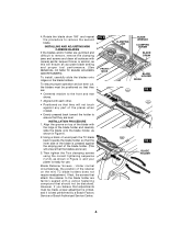
... toward the holder to remove, remove the clamping jaws and screws and clean all surfaces with a yellow fastening compound that they are level.) 3. lacquer thinner or alcohol, as this will ensure an accurate blade setting and proper tool performance. (See REMOVAL OF MINI TC BLADE HOLDERS AND RETAINERS) To install, carefully slide the blades onto ridges on the mini TC blade holders does not require readjustment. Using a block...
... toward the holder to remove, remove the clamping jaws and screws and clean all surfaces with a yellow fastening compound that they are level.) 3. lacquer thinner or alcohol, as this will ensure an accurate blade setting and proper tool performance. (See REMOVAL OF MINI TC BLADE HOLDERS AND RETAINERS) To install, carefully slide the blades onto ridges on the mini TC blade holders does not require readjustment. Using a block...

Operating Instructions
Page 9
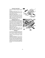
... before installation using the correct tightening sequence (1,2,3). (Fig. 4) 4. If the blade is gummed and difficult to keep your fingers away from the sharp edges of the blade. Rotate the blade drum until the clamping jaw is parallel to remove the second blade. -9- Rotate the blade drum until the clamping jaw is parallel to remove the second blade. To install the blades, carefully slide the blade/retainer assembly sideways to remove...
... before installation using the correct tightening sequence (1,2,3). (Fig. 4) 4. If the blade is gummed and difficult to keep your fingers away from the sharp edges of the blade. Rotate the blade drum until the clamping jaw is parallel to remove the second blade. -9- Rotate the blade drum until the clamping jaw is parallel to remove the second blade. To install the blades, carefully slide the blade/retainer assembly sideways to remove...
Operating Instructions
Page 10
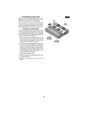
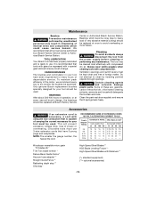
... be maintained when sharpening. Remove blade and retainer assembly from tips of the blades, both blades must be resharpened. RESHARPENING HSS BLADES Worn or dull HSS plane blades can be replaced because the minimum HSS blade height is required to the correct height and levelness. 3. BLADE LEVELING FIXTURE BLADE RETAINER FIG. 9 HSS BLADE -10- The optimal blade angle of the cutting edge to tip. Once a total...
... be maintained when sharpening. Remove blade and retainer assembly from tips of the blades, both blades must be resharpened. RESHARPENING HSS BLADES Worn or dull HSS plane blades can be replaced because the minimum HSS blade height is required to the correct height and levelness. 3. BLADE LEVELING FIXTURE BLADE RETAINER FIG. 9 HSS BLADE -10- The optimal blade angle of the cutting edge to tip. Once a total...
Operating Instructions
Page 11
... motor, the depth setting can cause the tool to 3/32" or 2.6 mm per pass. (Fig. 1) The appropriate depth of Cut: Rotate depth adjustment knob clockwise until you are held in place securely on your work ) and start the planer as described earlier. 2. To turn tool "ON": depress the "Lock-Off" release button from 0 to twist. Make sure that the blade drum is aligned with both hands while starting the tool, since torque...
... motor, the depth setting can cause the tool to 3/32" or 2.6 mm per pass. (Fig. 1) The appropriate depth of Cut: Rotate depth adjustment knob clockwise until you are held in place securely on your work ) and start the planer as described earlier. 2. To turn tool "ON": depress the "Lock-Off" release button from 0 to twist. Make sure that the blade drum is aligned with both hands while starting the tool, since torque...
Operating Instructions
Page 12
... to manually remove chips. Setting the cutting angle: Loosen round knobs and pivot the fence to break up the clog. Installing the angle fence: Place the wing knob through the appropriate hole in the guide bracket and screw into the dust port to the desired position. The depth of cut if contacted. Securely tighten wing knob (Fig. 1). Securely tighten wing knob (Fig. 1). Setting the cutting width: Loosen wing knob and using the deluxe angle/width fence...
... to manually remove chips. Setting the cutting angle: Loosen round knobs and pivot the fence to break up the clog. Installing the angle fence: Place the wing knob through the appropriate hole in the guide bracket and screw into the dust port to the desired position. The depth of cut if contacted. Securely tighten wing knob (Fig. 1). Securely tighten wing knob (Fig. 1). Setting the cutting width: Loosen wing knob and using the deluxe angle/width fence...
Operating Instructions
Page 13
... aligned (See "BLADE ALIGNMENT"). Installing new drive belt: Loosen screw and remove the drive belt cover. Before installing the new drive belt, clean both pulleys thoroughly. Setting the cutting width: Loosen wing knob and slide the fence along the guide bracket to cut various desired widths. (Fig. 14) Installing the guide fence: Place the wing knob through the appropriate hole in the guide bracket and screw into the housing. The maximum rabbeting depth is controlled...
... aligned (See "BLADE ALIGNMENT"). Installing new drive belt: Loosen screw and remove the drive belt cover. Before installing the new drive belt, clean both pulleys thoroughly. Setting the cutting width: Loosen wing knob and slide the fence along the guide bracket to cut various desired widths. (Fig. 14) Installing the guide fence: Place the wing knob through the appropriate hole in the guide bracket and screw into the housing. The maximum rabbeting depth is controlled...
Operating Instructions
Page 14
... heavy load or very abrasive material cutting) should be regreased with Retainers ** (*= standard equipment) (**= optional accessories) -14- Ventilation openings and switch levers must use . Clean the park rest shoe regularly and ensure that tools with gears be replaced at Bosch Factory Service Center or Authorized Bosch Service Station. NOTE: The smaller the gauge number, the heavier the cord. RECOMMENDED SIZES OF EXTENSION CORDS 120 VOLT ALTERNATING CURRENT TOOLS Tool's Ampere Rating Cord Size...
... heavy load or very abrasive material cutting) should be regreased with Retainers ** (*= standard equipment) (**= optional accessories) -14- Ventilation openings and switch levers must use . Clean the park rest shoe regularly and ensure that tools with gears be replaced at Bosch Factory Service Center or Authorized Bosch Service Station. NOTE: The smaller the gauge number, the heavier the cord. RECOMMENDED SIZES OF EXTENSION CORDS 120 VOLT ALTERNATING CURRENT TOOLS Tool's Ampere Rating Cord Size...
Parts Diagram
Page 2
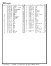
...064 Clamp {2} 80 89 74 2 608 635 405 Blade Set (PA1202) 94 9 75 2 602 316 001 Guide {2} 80 25 76 2 609 110 107 Holder {2} 80 64 80 2 609 100 088 Foot 9 89 81 2 609 110 109 Spring 27 89 201 2 603 433 001 Screw {4} 89 89 202 2 916 069 088 Washer ... 2 609 100 028 2 601 329 053 2 917 800 053 Description {Qty.} Field 120V Armature w/Fan 120V Switch Terminal Sleeve {2} Strain Relief Cord Clamp Nameplate Label Screw {2} Label Brush Holder {2} Brush Cap {2} Screw {14} Screw Nut Pulley Pulley Handle Belt Cover Spring Cover Cap Dial Baffle Spring Clip Roll Pin Service Notes: F/C Pos.
...064 Clamp {2} 80 89 74 2 608 635 405 Blade Set (PA1202) 94 9 75 2 602 316 001 Guide {2} 80 25 76 2 609 110 107 Holder {2} 80 64 80 2 609 100 088 Foot 9 89 81 2 609 110 109 Spring 27 89 201 2 603 433 001 Screw {4} 89 89 202 2 916 069 088 Washer ... 2 609 100 028 2 601 329 053 2 917 800 053 Description {Qty.} Field 120V Armature w/Fan 120V Switch Terminal Sleeve {2} Strain Relief Cord Clamp Nameplate Label Screw {2} Label Brush Holder {2} Brush Cap {2} Screw {14} Screw Nut Pulley Pulley Handle Belt Cover Spring Cover Cap Dial Baffle Spring Clip Roll Pin Service Notes: F/C Pos.


