
U8768 user's manual
Page 4
... 1 Motherboard Description Notice Introduction of system This mainboard is designed to take advantage of its predecessors, this mainboard continues a commitment to provide you with PC Micro-ATX form factor specifications. 4.Supports popular operating systems such as hard disks and CD-ROM Drives. 3.Supports the Intel Pentium ® 4 processor, a leading edge processor. U8768...
... 1 Motherboard Description Notice Introduction of system This mainboard is designed to take advantage of its predecessors, this mainboard continues a commitment to provide you with PC Micro-ATX form factor specifications. 4.Supports popular operating systems such as hard disks and CD-ROM Drives. 3.Supports the Intel Pentium ® 4 processor, a leading edge processor. U8768...
U8768 user's manual
Page 5
... 2.53 GHz CPU core speeds. 3.The 33MHz 32 bit PCI 2.2 compliant. 4.The 66MHz AGP 2.0 compliant interface supports 1x, 2x and 4x data transfer mode. Chapter 1 Motherboard Description Mainboard Features 1.
... 2.53 GHz CPU core speeds. 3.The 33MHz 32 bit PCI 2.2 compliant. 4.The 66MHz AGP 2.0 compliant interface supports 1x, 2x and 4x data transfer mode. Chapter 1 Motherboard Description Mainboard Features 1.
U8768 user's manual
Page 6
... BIOS. Contains 3 32-bit PCI bus slots Flash Memory: 1.Supports flash memory functionality. 2.Supports ESCD functionality. BUS Slots: 1.Contains 1 AGP slot. 2.Contains 1 CNR slot. 3. Chapter 1 Motherboard Description Shadow RAM: Motherboard is equipped with CD-ROM. 6.Supports high capacity hard disk drives. 7.Supports LBA mode. 1-3
... BIOS. Contains 3 32-bit PCI bus slots Flash Memory: 1.Supports flash memory functionality. 2.Supports ESCD functionality. BUS Slots: 1.Contains 1 AGP slot. 2.Contains 1 CNR slot. 3. Chapter 1 Motherboard Description Shadow RAM: Motherboard is equipped with CD-ROM. 6.Supports high capacity hard disk drives. 7.Supports LBA mode. 1-3
U8768 user's manual
Page 7
.... Enhanced Parallel Port (EPP). Meet Microsoft's ® PC2001 requirements. 11. Extended Capabilities Port (ECP). Hardware Monitor Function: 1.Monitors CPU Fan Speed. 2.Monitors System Voltage. 1-4 Chapter 1 Motherboard Description AC'97 Sound Codec Onboard: 1.AC-LINK protocol comfliance. 2.Compliant with AC'97 specification. 3.18-bit full duplex stereo ADC, DACs. 4.SNR>95 Bb...
.... Enhanced Parallel Port (EPP). Meet Microsoft's ® PC2001 requirements. 11. Extended Capabilities Port (ECP). Hardware Monitor Function: 1.Monitors CPU Fan Speed. 2.Monitors System Voltage. 1-4 Chapter 1 Motherboard Description AC'97 Sound Codec Onboard: 1.AC-LINK protocol comfliance. 2.Compliant with AC'97 specification. 3.18-bit full duplex stereo ADC, DACs. 4.SNR>95 Bb...
U8768 user's manual
Page 8
Chapter 1 Dimensions (MATX form-factor): 24.5cm x 22.8cm (WxL) Motherboard Description 1-5
Chapter 1 Dimensions (MATX form-factor): 24.5cm x 22.8cm (WxL) Motherboard Description 1-5
U8768 user's manual
Page 9
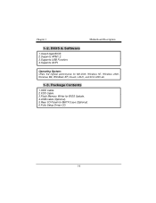
Operating System: Offers the highest performance for MATX Case (Optional). 6.Fully Setup Driver CD. 1-6 Package Contents 1.HDD Cable. 2.FDD Cable. 3.Flash Memory Writer for BIOS Update. 4.USB Cable (Optional). 5.Rear I/O Panel for MS-DOS, Windows NT, Windows 2000, Windows ME, Windows XP, Novell, LINUX, and SCO UNIX etc. 1-3. BIOS & Software 1.Award legal BIOS. 2.Supports APM1.2. 3.Supports USB Function. 4.Supports ACPI. Chapter 1 Motherboard Description 1-2.
Operating System: Offers the highest performance for MATX Case (Optional). 6.Fully Setup Driver CD. 1-6 Package Contents 1.HDD Cable. 2.FDD Cable. 3.Flash Memory Writer for BIOS Update. 4.USB Cable (Optional). 5.Rear I/O Panel for MS-DOS, Windows NT, Windows 2000, Windows ME, Windows XP, Novell, LINUX, and SCO UNIX etc. 1-3. BIOS & Software 1.Award legal BIOS. 2.Supports APM1.2. 3.Supports USB Function. 4.Supports ACPI. Chapter 1 Motherboard Description 1-2.
U8768 user's manual
Page 10
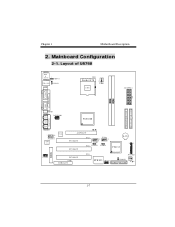
Chapter 1 Motherboard Description 2. JPRNT1 JCOM2 J AT X P W R 2 P4X266E Game Port In Out MIC Line Speaker In JGAME1 2 10 1 9 JAUDIO1 CMI 9739 VT6103 AGP SLOT PCI SLOT PCI SLOT ... JUSBV4 VT8235 BAT1 24 23 BIOS 1 JCDIN1 PCI SLOT CNR1 CNR SLOT PCI3 21 JPANEL1 ITE I/O JWOL1 1 JCMOS1 1 FLOPPY DISK CONN. 1-7 Mainboard Configuration 2-1. Layout of U8768 JKBMS1 K/B & Mouse 1 JKBV1 JUSBLAN1 1 USB & LAN JUSBV1 JCOM1 CPU1 Socket 478 CPU J AT X P W R 1 COM1 Parallel Port COM2 PRIMARY IDE CONN. SECONDARY IDE CONN...
Chapter 1 Motherboard Description 2. JPRNT1 JCOM2 J AT X P W R 2 P4X266E Game Port In Out MIC Line Speaker In JGAME1 2 10 1 9 JAUDIO1 CMI 9739 VT6103 AGP SLOT PCI SLOT PCI SLOT ... JUSBV4 VT8235 BAT1 24 23 BIOS 1 JCDIN1 PCI SLOT CNR1 CNR SLOT PCI3 21 JPANEL1 ITE I/O JWOL1 1 JCMOS1 1 FLOPPY DISK CONN. 1-7 Mainboard Configuration 2-1. Layout of U8768 JKBMS1 K/B & Mouse 1 JKBV1 JUSBLAN1 1 USB & LAN JUSBV1 JCOM1 CPU1 Socket 478 CPU J AT X P W R 1 COM1 Parallel Port COM2 PRIMARY IDE CONN. SECONDARY IDE CONN...
U8768 user's manual
Page 11
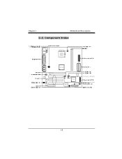
Component Index Socket 478 CPU BIOS CMI 9739 VT6103 P4X266E ITE I/O B AT1 VT8235 5V/ 5VSB Selection for USB (JUSBV4) 5V/ 5VSB Selection for USB (JUSBV3) 1-8 Chapter 1 Motherboard Description 2-2.
Component Index Socket 478 CPU BIOS CMI 9739 VT6103 P4X266E ITE I/O B AT1 VT8235 5V/ 5VSB Selection for USB (JUSBV4) 5V/ 5VSB Selection for USB (JUSBV3) 1-8 Chapter 1 Motherboard Description 2-2.
U8768 user's manual
Page 12
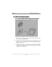
Match Pin A with the white dot/cut edge in the socket and look for the white dot or cut edge then insert the CPU. 3. CPU Configuration 3-1. Locate Pin A in the CPU. Press the lever down. Chapter 1 Motherboard Description 3. CPU Socket 478 Configuration Steps: CPU Fan CPU 1. Pull the lever sideways away from the socket then raise the lever up to complete the installation. 1-9 Then Put the fan on the CPU and buckle it and put the fan's power port into the JCFAN1, then to a 90-degree angle. 2.
Match Pin A with the white dot/cut edge in the socket and look for the white dot or cut edge then insert the CPU. 3. CPU Configuration 3-1. Locate Pin A in the CPU. Press the lever down. Chapter 1 Motherboard Description 3. CPU Socket 478 Configuration Steps: CPU Fan CPU 1. Pull the lever sideways away from the socket then raise the lever up to complete the installation. 1-9 Then Put the fan on the CPU and buckle it and put the fan's power port into the JCFAN1, then to a 90-degree angle. 2.
U8768 user's manual
Page 13
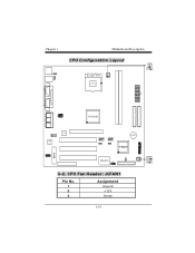
CPU Fan Header: JCFAN1 Pin No. 1 2 3 Assignment Ground +12V Sense 1-10 Chapter 1 Motherboard Description CPU Configuration Layout Socket 478 CPU P4X266E CMI 9739 VT6103 BAT1 VT8235 BIOS ITE I/O 3-2.
CPU Fan Header: JCFAN1 Pin No. 1 2 3 Assignment Ground +12V Sense 1-10 Chapter 1 Motherboard Description CPU Configuration Layout Socket 478 CPU P4X266E CMI 9739 VT6103 BAT1 VT8235 BIOS ITE I/O 3-2.
U8768 user's manual
Page 14
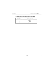
System Fan Header: JSFAN1 Pin No. 1 2 3 Assignment Ground +12V Sense 1-11 Chapter 1 Motherboard Description 3-3.
System Fan Header: JSFAN1 Pin No. 1 2 3 Assignment Ground +12V Sense 1-11 Chapter 1 Motherboard Description 3-3.
U8768 user's manual
Page 15
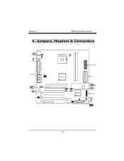
Jumpers, Headers & Connectors 1 JKBV1 1 JUSBV1 J AT X P W R 2 2 10 1 9 JUSB3 CMI 1 9739 JUSBV3 VT6103 BIOS Socket 478 CPU J AT X P W R 1 P4X266E IDE1-2 ITE I/O B AT 1 VT8235 JUSB4 2 10 1 9 1 JUSBV4 JPANEL1 JCMOS1 1 FDD1 JWOL1 1 1-12 Chapter 1 Motherboard Description 4.
Jumpers, Headers & Connectors 1 JKBV1 1 JUSBV1 J AT X P W R 2 2 10 1 9 JUSB3 CMI 1 9739 JUSBV3 VT6103 BIOS Socket 478 CPU J AT X P W R 1 P4X266E IDE1-2 ITE I/O B AT 1 VT8235 JUSB4 2 10 1 9 1 JUSBV4 JPANEL1 JCMOS1 1 FDD1 JWOL1 1 1-12 Chapter 1 Motherboard Description 4.
U8768 user's manual
Page 16
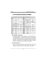
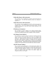
...Drive 10 Power LED (+) POWER 11 HDD LED (-) LED 12 Power LED (-) LED 13 Ground Reset 14 Power Button Power-on the motherboard as a manufacturing option. The speaker (onboard or offboard) provides error beep code information during the Power On Self-Test when the computer cannot... Connector) An offboard speaker can be connected to the audio subsystem and does not receive output from the audio subsystem. Chapter 1 Motherboard Description 4-1. Front Panel Connector: JPANEL1 Pin Assignment Function Pin Assignment Function No. An offboard speaker can be attached to reset and ...
...Drive 10 Power LED (+) POWER 11 HDD LED (-) LED 12 Power LED (-) LED 13 Ground Reset 14 Power Button Power-on the motherboard as a manufacturing option. The speaker (onboard or offboard) provides error beep code information during the Power On Self-Test when the computer cannot... Connector) An offboard speaker can be connected to the audio subsystem and does not receive output from the audio subsystem. Chapter 1 Motherboard Description 4-1. Front Panel Connector: JPANEL1 Pin Assignment Function Pin Assignment Function No. An offboard speaker can be attached to reset and ...
U8768 user's manual
Page 17
... (Advanced Power Management) must pull the Power Button pin to ground for at least 50 ms to signal the power supply to switch on . Chapter 1 Motherboard Description POW-LED (Power LED Connector) This connector can be attached to the system board. This disk activity only applies to those IDE drives directly...
... (Advanced Power Management) must pull the Power Button pin to ground for at least 50 ms to signal the power supply to switch on . Chapter 1 Motherboard Description POW-LED (Power LED Connector) This connector can be attached to the system board. This disk activity only applies to those IDE drives directly...
U8768 user's manual
Page 18
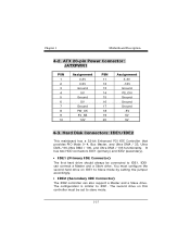
... Ground -5V 5V 5V 4-3. IDE1 can also support a Master and a Slave drive. The configuration is similar to IDE1. You must be connected to IDE1. Chapter 1 Motherboard Description 4-2. Hard Disk Connectors: IDE1/IDE2 This mainboard has a 32-bit Enhanced PCI IDE Controller that provides PIO Mode 0~4, Bus Master, and Ultra DMA / 33...
... Ground -5V 5V 5V 4-3. IDE1 can also support a Master and a Slave drive. The configuration is similar to IDE1. You must be connected to IDE1. Chapter 1 Motherboard Description 4-2. Hard Disk Connectors: IDE1/IDE2 This mainboard has a 32-bit Enhanced PCI IDE Controller that provides PIO Mode 0~4, Bus Master, and Ultra DMA / 33...
U8768 user's manual
Page 19
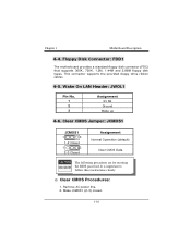
... Data The following procedures are for resetting the BIOS password. It is important to follow these instructions closely. ※ Clear CMOS Procedures: 1. Chapter 1 Motherboard Description 4-4. Make JCMOS1 (2-3) closed. 1-16 Floppy Disk Connector: FDD1 The motherboard provides a standard floppy disk connector (FDC) that supports 360K, 720K, 1.2M, 1.44M and 2.88M floppy disk types.
... Data The following procedures are for resetting the BIOS password. It is important to follow these instructions closely. ※ Clear CMOS Procedures: 1. Chapter 1 Motherboard Description 4-4. Make JCMOS1 (2-3) closed. 1-16 Floppy Disk Connector: FDD1 The motherboard provides a standard floppy disk connector (FDC) that supports 360K, 720K, 1.2M, 1.44M and 2.88M floppy disk types.
U8768 user's manual
Page 20
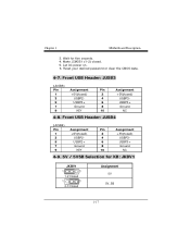
...) 4 USBP3- 6 USBP3+ 8 Ground 10 NC 4-9. 5V / 5VSB Selection for five seconds. 4. Reset your desired password or clear the CMOS data. 4-7. Let AC power on. 6. Chapter 1 Motherboard Description 3. Make JCMOS1 (1-2) closed. 5. Front USB Header: JUSB3 (JUSB3) Pin 1 3 5 7 9 Assignment +5V(fused) USBP2USBP2+ Ground KEY Pin Assignment 2 +5V(fused) 4 USBP3- 6 USBP3+ 8 Ground 10 NC...
...) 4 USBP3- 6 USBP3+ 8 Ground 10 NC 4-9. 5V / 5VSB Selection for five seconds. 4. Reset your desired password or clear the CMOS data. 4-7. Let AC power on. 6. Chapter 1 Motherboard Description 3. Make JCMOS1 (1-2) closed. 5. Front USB Header: JUSB3 (JUSB3) Pin 1 3 5 7 9 Assignment +5V(fused) USBP2USBP2+ Ground KEY Pin Assignment 2 +5V(fused) 4 USBP3- 6 USBP3+ 8 Ground 10 NC...
U8768 user's manual
Page 21
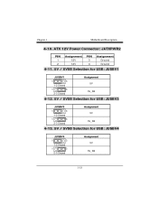
ATX 12V Power Connector: JATXPWR2 PIN 1 2 Assignment 12V 12V PIN 3 4 Assignment Ground Ground 4-11. 5V / 5VSB Selection for USB: JUSBV1 JUSBV1 1 3 1-2 Closed 1 3 2-3 Closed Assignment 5V 5V_SB 4-12. 5V / 5VSB Selection for USB: JUSBV3 JUSBV3 1 3 1-2 Closed 1 3 2-3 Closed Assignment 5V 5V_SB 4-13. 5V / 5VSB Selection for USB: JUSBV4 JUSBV4 1 3 1-2 Closed 1 3 2-3 Closed Assignment 5V 5V_SB 1-18 Chapter 1 Motherboard Description 4-10.
ATX 12V Power Connector: JATXPWR2 PIN 1 2 Assignment 12V 12V PIN 3 4 Assignment Ground Ground 4-11. 5V / 5VSB Selection for USB: JUSBV1 JUSBV1 1 3 1-2 Closed 1 3 2-3 Closed Assignment 5V 5V_SB 4-12. 5V / 5VSB Selection for USB: JUSBV3 JUSBV3 1 3 1-2 Closed 1 3 2-3 Closed Assignment 5V 5V_SB 4-13. 5V / 5VSB Selection for USB: JUSBV4 JUSBV4 1 3 1-2 Closed 1 3 2-3 Closed Assignment 5V 5V_SB 1-18 Chapter 1 Motherboard Description 4-10.
U8768 user's manual
Page 22
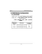
DRAM Type: 128MB/ 256MB/ 512MB/ 1GB DIMM Module (184 pin) Total Memory Size with unbuffer DIMMs (Only for reference) DIMM Socket Location DDR Module Total Memory Size (MB) DDR 1 64MB/128MB/256MB/512MB/1GB *1 Max is DDR 2 64MB/128MB/256MB/512MB/1GB 2GB *1 1-19 DDR SDRAM DRAM Access Time: 2.5V Unbuffered DDR SDRAM PC1600/ PC2100 Type required. Chapter 1 Motherboard Description 5. RAM Module Configuration 5-1.
DRAM Type: 128MB/ 256MB/ 512MB/ 1GB DIMM Module (184 pin) Total Memory Size with unbuffer DIMMs (Only for reference) DIMM Socket Location DDR Module Total Memory Size (MB) DDR 1 64MB/128MB/256MB/512MB/1GB *1 Max is DDR 2 64MB/128MB/256MB/512MB/1GB 2GB *1 1-19 DDR SDRAM DRAM Access Time: 2.5V Unbuffered DDR SDRAM PC1600/ PC2100 Type required. Chapter 1 Motherboard Description 5. RAM Module Configuration 5-1.
U8768 user's manual
Page 24
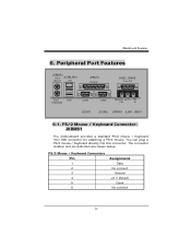
... definition are shown below: PS/2 Mouse / Keyboard Connectors Pin 1 2 3 4 5 6 Assignment Data No connect Ground +5 V (fused) Clock No connect 21 PS/2 Mouse / Keyboard Connector: JKBMS1 The motherboard provides a standard PS/2 mouse / Keyboard mini DIN connector for attaching a PS/2 mouse. Peripheral Port Features JKBMS1 PS/2 JUSBLAN1 Mouse LAN JPRNT1 Parallel JAUD_GAME Game Port...
... definition are shown below: PS/2 Mouse / Keyboard Connectors Pin 1 2 3 4 5 6 Assignment Data No connect Ground +5 V (fused) Clock No connect 21 PS/2 Mouse / Keyboard Connector: JKBMS1 The motherboard provides a standard PS/2 mouse / Keyboard mini DIN connector for attaching a PS/2 mouse. Peripheral Port Features JKBMS1 PS/2 JUSBLAN1 Mouse LAN JPRNT1 Parallel JAUD_GAME Game Port...

