
TForce4 U user's manual
Page 2
... RUSSIAN ...22 ARABIC ...23 JAPANESE ...24 ii User's Manual Central Processing Unit (CPU) ...3 B. Card and I CHAPTER 1: INTRODUCTION ...1 1.1 MOTHERBOARD FEATURES ...1 1.2 LAYOUT AND COMPONENTS ...2 CHAPTER 2: HARDWARE INSTALLATIONS ...3 2.1 CPU ASSEMBLY ...3 A. Memory Space...4 C. DDR Installation Notice...4 D. DDR ... 4.1 AWARD BIOS BEEP CODE...14 4.2 EXTRA INFORMATION ...14 A. Biostar T-Series TForce4/ TForce4 U PACKAGE CHECKLIST ...I /O Slots:...5 B. About FAN Headers ...3 2.2 SYSTEM MEMORY...4 A. Know your CPU version ...4 2.3 PERIPHERALS ...5 A.
... RUSSIAN ...22 ARABIC ...23 JAPANESE ...24 ii User's Manual Central Processing Unit (CPU) ...3 B. Card and I CHAPTER 1: INTRODUCTION ...1 1.1 MOTHERBOARD FEATURES ...1 1.2 LAYOUT AND COMPONENTS ...2 CHAPTER 2: HARDWARE INSTALLATIONS ...3 2.1 CPU ASSEMBLY ...3 A. Memory Space...4 C. DDR Installation Notice...4 D. DDR ... 4.1 AWARD BIOS BEEP CODE...14 4.2 EXTRA INFORMATION ...14 A. Biostar T-Series TForce4/ TForce4 U PACKAGE CHECKLIST ...I /O Slots:...5 B. About FAN Headers ...3 2.2 SYSTEM MEMORY...4 A. Know your CPU version ...4 2.3 PERIPHERALS ...5 A.
TForce4 U user's manual
Page 3
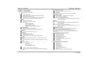
Biostar T-Series Chapter 1: Introduction 1.1 MOTHERBOARD FEATURES CPU Supports Socket 939. Dimensions ATX Form Factor: 23.4cm (W) x 29.35cm (L) Main Memory Supports Dual Channel DDR. Supports DDR333 and DDR400. Maximum memory ... Guardian" function IDE 2 on-board connectors support 4 IDE disk drives. Supports PIO mode 0~4, Block Mode and Ultra DMA 33/66/100/133 bus master mode. 1 TForce4/ TForce4 U AC'97 Audio Sound Codec Chip: ALC850, supports 8 channels audio output. Gigabit Ethernet LAN NVIDIA Gigabit MAC + VITESSE Gigabit PHY VSC8201. Supports NVIDIA StreamThru technology...
Biostar T-Series Chapter 1: Introduction 1.1 MOTHERBOARD FEATURES CPU Supports Socket 939. Dimensions ATX Form Factor: 23.4cm (W) x 29.35cm (L) Main Memory Supports Dual Channel DDR. Supports DDR333 and DDR400. Maximum memory ... Guardian" function IDE 2 on-board connectors support 4 IDE disk drives. Supports PIO mode 0~4, Block Mode and Ultra DMA 33/66/100/133 bus master mode. 1 TForce4/ TForce4 U AC'97 Audio Sound Codec Chip: ALC850, supports 8 channels audio output. Gigabit Ethernet LAN NVIDIA Gigabit MAC + VITESSE Gigabit PHY VSC8201. Supports NVIDIA StreamThru technology...
TForce4 U user's manual
Page 7
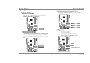
...for Peripheral Component Interconnect, and it is equipped with 3 standard PCI slots. Maximum bandwidth is up to 250MB/s per direction. Biostar T-Series 2.3 PERIPHERALS A. The first hard drive should always be connected to four hard disk drives. Maximum bandwidth is designated as...IDE1 2 Codec BIOS 5 Codec BIOS PCI-EX x1 PEX1-2 PCI-EX x1 PEX1-1 PCI-EX16 User's Manual TForce4/ TForce4 U Peripheral Component Interconnect Slots: PCI1~PCI3 This motherboard is a bus standard for expansion cards. PCI Express 1.0a compliant. - The IDE connectors can connect a master ...
...for Peripheral Component Interconnect, and it is equipped with 3 standard PCI slots. Maximum bandwidth is up to 250MB/s per direction. Biostar T-Series 2.3 PERIPHERALS A. The first hard drive should always be connected to four hard disk drives. Maximum bandwidth is designated as...IDE1 2 Codec BIOS 5 Codec BIOS PCI-EX x1 PEX1-2 PCI-EX x1 PEX1-1 PCI-EX16 User's Manual TForce4/ TForce4 U Peripheral Component Interconnect Slots: PCI1~PCI3 This motherboard is a bus standard for expansion cards. PCI Express 1.0a compliant. - The IDE connectors can connect a master ...
TForce4 U user's manual
Page 11
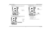
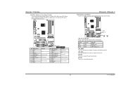
...Wait for five seconds. 4. If the signal has been triggered, it will record to "Pin 1-2 Close". 5. Remove AC power line. 2. Biostar T-Series Case Open Header: JCI1 This connector allows system to monitor PC case open signal 2 Ground JCI1 12 Codec BIOS Serial ATA Connectors: JSATA1... 7 41 Pin Assignment 1 Ground 2 TX+ 3 TX4 Ground 5 RX6 RX+ 7 Ground Codec BIOS TForce4/ TForce4 U Clear CMOS Header: JCMOS1 By placing the jumper on the AC. 6. Set the jumper to avoid damaging the motherboard. 13 Pin 1-2 Close: Normal Operation (default). 13 JCMOS1 Pin 2-3 Close: Clear CMOS data. 1...
...Wait for five seconds. 4. If the signal has been triggered, it will record to "Pin 1-2 Close". 5. Remove AC power line. 2. Biostar T-Series Case Open Header: JCI1 This connector allows system to monitor PC case open signal 2 Ground JCI1 12 Codec BIOS Serial ATA Connectors: JSATA1... 7 41 Pin Assignment 1 Ground 2 TX+ 3 TX4 Ground 5 RX6 RX+ 7 Ground Codec BIOS TForce4/ TForce4 U Clear CMOS Header: JCMOS1 By placing the jumper on the AC. 6. Set the jumper to avoid damaging the motherboard. 13 Pin 1-2 Close: Normal Operation (default). 13 JCMOS1 Pin 2-3 Close: Clear CMOS data. 1...
TForce4 U user's manual
Page 12
... on -board Power Switch button. TForce4/ TForce4 U LED Indicators and Buttons There are 4 LED indicators on , Reset, HDD LED, Power LED, Sleep button, speaker and IrDA Connection. PWRSW: This is an on . Biostar T-Series JPANEL1: Header for Front Panel Facilities This 24-pin connector includes Power-on the motherboard to the table below for...
... on -board Power Switch button. TForce4/ TForce4 U LED Indicators and Buttons There are 4 LED indicators on , Reset, HDD LED, Power LED, Sleep button, speaker and IrDA Connection. PWRSW: This is an on . Biostar T-Series JPANEL1: Header for Front Panel Facilities This 24-pin connector includes Power-on the motherboard to the table below for...
TForce4 U user's manual
Page 16
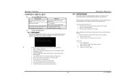
...bootable disk into floppy drive and press Enter. 6. System will work properly. TForce4/ TForce4 U B. In this case, please follow the steps below to restore the BIOS: 1. CPU fan is over heated, the motherboard will shutdown automatically to avoid damaging the CPU, and the system will boot-up...) 2. Power on of the system, it means the BIOS contents are corrupted. Make a bootable floppy disk. 2. Confirm motherboard model and download the respective BIOS from Biostar website. 4. The BIOS has been recovered and will update BIOS automatically and restart. 9. Wait for a few seconds that ...
...bootable disk into floppy drive and press Enter. 6. System will work properly. TForce4/ TForce4 U B. In this case, please follow the steps below to restore the BIOS: 1. CPU fan is over heated, the motherboard will shutdown automatically to avoid damaging the CPU, and the system will boot-up...) 2. Power on of the system, it means the BIOS contents are corrupted. Make a bootable floppy disk. 2. Confirm motherboard model and download the respective BIOS from Biostar website. 4. The BIOS has been recovered and will update BIOS automatically and restart. 9. Wait for a few seconds that ...


