
TForce4 U user's manual
Page 3
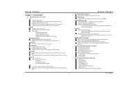
... ME. Supports PIO mode 0~4, Block Mode and Ultra DMA 33/66/100/133 bus master mode. 1 TForce4/ TForce4 U AC'97 Audio Sound Codec Chip: ALC850, supports 8 channels audio output. IEEE 1394A Chip Chip: VIA VT6307, supports 2 ports with data transfer rates up to 1.5Gb...; Isochronous controller paired with an environment both SATA and ATA-133 disk controller standards. One CD-ROM audio-in fastest networking performance. Three PCI slots. Biostar T-Series Chapter 1: Introduction 1.1 MOTHERBOARD FEATURES CPU Supports Socket 939. AMD 64 architecture enables simultaneous 32 and...
... ME. Supports PIO mode 0~4, Block Mode and Ultra DMA 33/66/100/133 bus master mode. 1 TForce4/ TForce4 U AC'97 Audio Sound Codec Chip: ALC850, supports 8 channels audio output. IEEE 1394A Chip Chip: VIA VT6307, supports 2 ports with data transfer rates up to 1.5Gb...; Isochronous controller paired with an environment both SATA and ATA-133 disk controller standards. One CD-ROM audio-in fastest networking performance. Three PCI slots. Biostar T-Series Chapter 1: Introduction 1.1 MOTHERBOARD FEATURES CPU Supports Socket 939. AMD 64 architecture enables simultaneous 32 and...
TForce4 U user's manual
Page 9
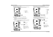
...: J1394_USBV1/JUSBV1 Pin 1-2 Close: J1394_USBV1: +5V for front USB headers (JUSB1/JUSB2/JUSB3). Biostar T-Series CD-ROM Audio-in Connector: JCDIN1 This connector allows user to connect the audio source from a variety of devices, like USB card reader. JUSBV1: Front USB headers (JUSB1/JUSB2.../JUSB3) are powered with +5V standby voltage. Pin 2-3 Close: J1394_USBV1: USB ports at PC front panel, and also can be placed on Pin 2-3 individually. 31 Codec BIOS 7 TForce4/ TForce4 ...
...: J1394_USBV1/JUSBV1 Pin 1-2 Close: J1394_USBV1: +5V for front USB headers (JUSB1/JUSB2/JUSB3). Biostar T-Series CD-ROM Audio-in Connector: JCDIN1 This connector allows user to connect the audio source from a variety of devices, like USB card reader. JUSBV1: Front USB headers (JUSB1/JUSB2.../JUSB3) are powered with +5V standby voltage. Pin 2-3 Close: J1394_USBV1: USB ports at PC front panel, and also can be placed on Pin 2-3 individually. 31 Codec BIOS 7 TForce4/ TForce4 ...
TForce4 U user's manual
Page 10
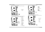
...11 Right line-in (optional) 12 Right line-in (optional) Codec BIOS 13 Left line-in (optional) 14 Left line-in (optional) 8 TForce4/ TForce4 U Power Source Header for 1394 Chip: J1394PWR1 3 1 Pin 1-2 Close: +3.3V for 1394 chipset (default). 3 1 J1394PWR1 31 Pin 2-3 Close... Header: JAUDIO2 This connector will disable the output on the PC case. Biostar T-Series Digital Audio-out Connector: JSPDIF_OUT This connector allows users to connect with the front audio output headers on back panel audio connectors. It will allow user to connect the PCI bracket SPDIF output header. Pin...
...11 Right line-in (optional) 12 Right line-in (optional) Codec BIOS 13 Left line-in (optional) 14 Left line-in (optional) 8 TForce4/ TForce4 U Power Source Header for 1394 Chip: J1394PWR1 3 1 Pin 1-2 Close: +3.3V for 1394 chipset (default). 3 1 J1394PWR1 31 Pin 2-3 Close... Header: JAUDIO2 This connector will disable the output on the PC case. Biostar T-Series Digital Audio-out Connector: JSPDIF_OUT This connector allows users to connect with the front audio output headers on back panel audio connectors. It will allow user to connect the PCI bracket SPDIF output header. Pin...

