
Setup Manual
Page 3
...bag, ground yourself properly by touching any unfastened small parts inside the case after installation. CHAPTER 1: INTRODUCTION TForce 6100 AM2 1.1 BEFORE YOU START Thank you take the motherboard out from dangerous area, such as heat source, humid air and water. 1.2 PACKAGE CHECKLIST FDD Cable X... X 1 Serial ATA Cable X 1 Serial ATA Power Cable X 1 Rear I/O Panel for choosing our product. Before you start installing the motherboard, please make sure you follow the instructions below: „ Prepare a dry and stable working environment with sufficient lighting. „ Always disconnect ...
...bag, ground yourself properly by touching any unfastened small parts inside the case after installation. CHAPTER 1: INTRODUCTION TForce 6100 AM2 1.1 BEFORE YOU START Thank you take the motherboard out from dangerous area, such as heat source, humid air and water. 1.2 PACKAGE CHECKLIST FDD Cable X... X 1 Serial ATA Cable X 1 Serial ATA Power Cable X 1 Rear I/O Panel for choosing our product. Before you start installing the motherboard, please make sure you follow the instructions below: „ Prepare a dry and stable working environment with sufficient lighting. „ Always disconnect ...
Setup Manual
Page 11
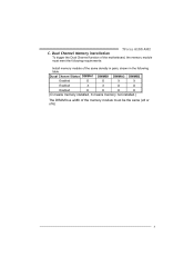
TForce 6100 AM2 C. Dual Channel Memory installation To trigger the Dual Channel function of the motherboard, the memory module must meet the following table. Duual Channel Status DIMMA1 DIMMB1 DIMMA2 DIMMB2 Enabled O O X X Enabled X X O O Enabled O O O O (O means memory installed, X means memory not installed.) The DRAM bus width of the same density in pairs, shown in the following requirements: Install memory module of the memory module must be the same (x8 or x16) 9
TForce 6100 AM2 C. Dual Channel Memory installation To trigger the Dual Channel function of the motherboard, the memory module must meet the following table. Duual Channel Status DIMMA1 DIMMB1 DIMMA2 DIMMB2 Enabled O O X X Enabled X X O O Enabled O O O O (O means memory installed, X means memory not installed.) The DRAM bus width of the same density in pairs, shown in the following requirements: Install memory module of the memory module must be the same (x8 or x16) 9
Setup Manual
Page 13
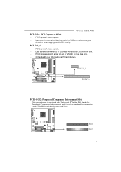
...bit-rate of 4GB/s simultaneously per direction; 500MB/s in total. - P CI -E X1_1 PC IE X16 PCI1~PCI2: Peripheral Component Interconnect Slots This motherboard is designated as 32 bits. PCI-Ex1_1 - Data transfer bandwidth up to 250MB/s per direction, for expansion cards. PCI-Express 1.0a compliant. - PCI stands...Maximum theoretical realized bandwidth of 2.5Gb/s on the data pins. - 2X bandwidth over the traditional PCI architecture. PCI-Express 1.0a compliant. - TForce 6100 AM2 PCI-Ex16: PCI-Express x16 Slot - This PCI slot is equipped with 2 standard PCI slots. PCI1 PCI2 11
...bit-rate of 4GB/s simultaneously per direction; 500MB/s in total. - P CI -E X1_1 PC IE X16 PCI1~PCI2: Peripheral Component Interconnect Slots This motherboard is designated as 32 bits. PCI-Ex1_1 - Data transfer bandwidth up to 250MB/s per direction, for expansion cards. PCI-Express 1.0a compliant. - PCI stands...Maximum theoretical realized bandwidth of 2.5Gb/s on the data pins. - 2X bandwidth over the traditional PCI architecture. PCI-Express 1.0a compliant. - TForce 6100 AM2 PCI-Ex16: PCI-Express x16 Slot - This PCI slot is equipped with 2 standard PCI slots. PCI1 PCI2 11
Setup Manual
Page 15
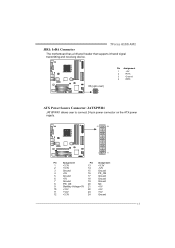
TForce 6100 AM2 JIR1: IrDA Connector The motherboard has a Infrared header that supports infrared signal transmitting and receiving device. IR(opt ional) 2 4 1 3 Pin Assignment 1 +5V 2 IRT X 3 Ground 4 IRRX ATX Power Source Connector: JATXPWR1 ...
TForce 6100 AM2 JIR1: IrDA Connector The motherboard has a Infrared header that supports infrared signal transmitting and receiving device. IR(opt ional) 2 4 1 3 Pin Assignment 1 +5V 2 IRT X 3 Ground 4 IRRX ATX Power Source Connector: JATXPWR1 ...
Setup Manual
Page 19
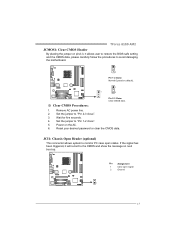
... has been triggered, it allows user to restore the BIOS safe setting and the CMOS data, please carefully follow the procedures to avoid damaging the motherboard. 1 3 Pin 1-2 Close: Normal Operation (default). 1 1 3 Pin 2-3 Close: Clear CMOS data. ※ Clear CMOS Procedures: 1. Power on next boot-up....Pin 2-3 close ". 5. Pin Assignment 1 Case open status. Reset your desired password or clear the CMOS data. Wait for five seconds. 4. TForce 6100 AM2 JCMOS1: Clear CMOS Header By placing the jumper on pin2-3, it will record to the CMOS and show the message on the AC. 6. Set...
... has been triggered, it allows user to restore the BIOS safe setting and the CMOS data, please carefully follow the procedures to avoid damaging the motherboard. 1 3 Pin 1-2 Close: Normal Operation (default). 1 1 3 Pin 2-3 Close: Clear CMOS data. ※ Clear CMOS Procedures: 1. Power on next boot-up....Pin 2-3 close ". 5. Pin Assignment 1 Case open status. Reset your desired password or clear the CMOS data. Wait for five seconds. 4. TForce 6100 AM2 JCMOS1: Clear CMOS Header By placing the jumper on pin2-3, it will record to the CMOS and show the message on the AC. 6. Set...
Setup Manual
Page 45
...8. Make a bootable floppy disk. 2. Confirm motherboard model and download the respectively BIOS from the Biostar website: www.biostar.com.tw 3. In this Case, please follow the procedure below to DOS prompt. 7. System will boot-up to restore the BIOS: 1. TForce 6100 AM2 6.2 AWARD BIOS BEEP CODE Beep Sound Meaning ... update BIOS automatically and restart. 9. System will work properly. 43 Download the Flash Utility "AWDFLASH.exe" from Biostar website. 4. Copy "AWDFLASH.exe" and respectively BIOS into floppy drive and press Enter. 6. Insert the bootable disk into floppy disk. 5....
...8. Make a bootable floppy disk. 2. Confirm motherboard model and download the respectively BIOS from the Biostar website: www.biostar.com.tw 3. In this Case, please follow the procedure below to DOS prompt. 7. System will boot-up to restore the BIOS: 1. TForce 6100 AM2 6.2 AWARD BIOS BEEP CODE Beep Sound Meaning ... update BIOS automatically and restart. 9. System will work properly. 43 Download the Flash Utility "AWDFLASH.exe" from Biostar website. 4. Copy "AWDFLASH.exe" and respectively BIOS into floppy drive and press Enter. 6. Insert the bootable disk into floppy disk. 5....
Setup Manual
Page 67
TForce 6100 AM2 BIOS Setup BIOS Setup Introduction The purpose of the EPA Green PC specification. Some additional features, such as defined in BIOS Setup. Plug and Play ... System (BIOS) determines what a computer can also be managed by a battery so that it retains the Setup information when the power is supplied by this motherboard. Sleep and Suspend power management modes are implemented via the System Management Interrupt (SMI). Power to CMOS RAM. The power of the input and output...
TForce 6100 AM2 BIOS Setup BIOS Setup Introduction The purpose of the EPA Green PC specification. Some additional features, such as defined in BIOS Setup. Plug and Play ... System (BIOS) determines what a computer can also be managed by a battery so that it retains the Setup information when the power is supplied by this motherboard. Sleep and Suspend power management modes are implemented via the System Management Interrupt (SMI). Power to CMOS RAM. The power of the input and output...
Setup Manual
Page 86
... or disable the IDE DMA transfer access. IDE DMA Transfer Access This item allows you are going to 4 will increase performance progressively. TForce 6100 AM2 BIOS Setup On-chip IDE Channel 0/1 The motherboard chipset contains a PCI IDE interface with support for each of the IDE devices that the onboard IDE interface supports. Select "Enabled...
... or disable the IDE DMA transfer access. IDE DMA Transfer Access This item allows you are going to 4 will increase performance progressively. TForce 6100 AM2 BIOS Setup On-chip IDE Channel 0/1 The motherboard chipset contains a PCI IDE interface with support for each of the IDE devices that the onboard IDE interface supports. Select "Enabled...


