

TForce 550 user's manual
Page 2
Table of Contents Chapter 1: Introduction 1 1.1 Before You Start 1 1.2 Package Checklist 1 1.3 Motherboard Features 2 1.4 Rear Panel Connectors 3 1.5 Motherboard Layout 4 Chapter 2: Hardware Installation 5 2.1 Installing Central Processing Unit (CPU 5 2.2 FAN Headers 6 2.3 Installing System Memory 8 2.4 Connectors and Slots 10 Chapter 3: Headers & Jumpers Setup 12 3.1 How to ...
Table of Contents Chapter 1: Introduction 1 1.1 Before You Start 1 1.2 Package Checklist 1 1.3 Motherboard Features 2 1.4 Rear Panel Connectors 3 1.5 Motherboard Layout 4 Chapter 2: Hardware Installation 5 2.1 Installing Central Processing Unit (CPU 5 2.2 FAN Headers 6 2.3 Installing System Memory 8 2.4 Connectors and Slots 10 Chapter 3: Headers & Jumpers Setup 12 3.1 How to ...
TForce 550 user's manual
Page 3
...grounded wrist strap to remove the static charge. „ Avoid touching the components on motherboard or the rear side of the board unless necessary. Before you start installing the motherboard, please make sure you follow the instructions below: „ Prepare a dry and stable... 1 HDD Cable X 1 Serial ATA Cable X 1 Serial ATA Power Cable X 1 Rear I/O Panel for choosing our product. TForce 550 CHAPTER 1: INTRODUCTION 1.1 BEFORE YOU START Thank you take the motherboard out from anti-static bag, ground yourself properly by touching any unfastened small parts inside the case after installation.
...grounded wrist strap to remove the static charge. „ Avoid touching the components on motherboard or the rear side of the board unless necessary. Before you start installing the motherboard, please make sure you follow the instructions below: „ Prepare a dry and stable... 1 HDD Cable X 1 Serial ATA Cable X 1 Serial ATA Power Cable X 1 Rear I/O Panel for choosing our product. TForce 550 CHAPTER 1: INTRODUCTION 1.1 BEFORE YOU START Thank you take the motherboard out from anti-static bag, ground yourself properly by touching any unfastened small parts inside the case after installation.
TForce 550 user's manual
Page 4
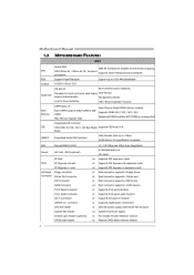
Motherboard Manual 1.3 MOTHERBOARD FEATURES SPEC Socket AM2 AMD 64 Architecture enables 32 and 64 bit computing CPU AMD Athlon 64 / Athlon 64 FX / Sempron Supports Hyper Transport and ... Smart Fan function) x3 System Fan Power supply x1 For chassis intruder detection function x1 Restore CMOS data to 1000 MHz Bandwidth Chipset nVIDIA nForce 550 Super I/O ITE 8712F Environment Control initiatives, Provides the most commonly used legacy H/W Monitor Super I/O functionality. SATA Version 2.0 specification compliant. Fan Speed Controller Low Pin Count...
Motherboard Manual 1.3 MOTHERBOARD FEATURES SPEC Socket AM2 AMD 64 Architecture enables 32 and 64 bit computing CPU AMD Athlon 64 / Athlon 64 FX / Sempron Supports Hyper Transport and ... Smart Fan function) x3 System Fan Power supply x1 For chassis intruder detection function x1 Restore CMOS data to 1000 MHz Bandwidth Chipset nVIDIA nForce 550 Super I/O ITE 8712F Environment Control initiatives, Provides the most commonly used legacy H/W Monitor Super I/O functionality. SATA Version 2.0 specification compliant. Fan Speed Controller Low Pin Count...
TForce 550 user's manual
Page 6
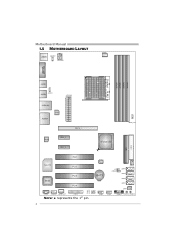
Motherboard Manual 1.5 MOTHERBOARD LAYOUT JCFAN1 JKBMS1 JKBMSV1 JATXPWR2 JCOM1 DDR2A1 DDR2B1 DDR2A2 DDR2B2 Socket A M2 JUSB3 JUSBV2 JUSB4 JATXPWR1 JUSBLAN1 LAN JAUDIO1 Codec PEX1_1 PEX1_2 PEX16_1 JDDRII_2.2V nForce 550 FDD1 IDE1 PCI1 JNFAN1 Super I/O PCI2 BIOS PCI3 BAT1 PCI4 LED1 LED2 JUSBV1 JCDIN1 JAUDIOF1 JSPDIF_OUT JPRNT1 Note: ■ represents the 1st pin. JUSB2 JCI1 JCMOS1 JSATA4 JSFAN2 JSATA3 JSATA2 JSATA1 JSFAN1 JUSB1 JPANEL1 RSTSW1 PWRSW1 4
Motherboard Manual 1.5 MOTHERBOARD LAYOUT JCFAN1 JKBMS1 JKBMSV1 JATXPWR2 JCOM1 DDR2A1 DDR2B1 DDR2A2 DDR2B2 Socket A M2 JUSB3 JUSBV2 JUSB4 JATXPWR1 JUSBLAN1 LAN JAUDIO1 Codec PEX1_1 PEX1_2 PEX16_1 JDDRII_2.2V nForce 550 FDD1 IDE1 PCI1 JNFAN1 Super I/O PCI2 BIOS PCI3 BAT1 PCI4 LED1 LED2 JUSBV1 JCDIN1 JAUDIOF1 JSPDIF_OUT JPRNT1 Note: ■ represents the 1st pin. JUSB2 JCI1 JCMOS1 JSATA4 JSFAN2 JSATA3 JSATA2 JSATA1 JSFAN1 JUSB1 JPANEL1 RSTSW1 PWRSW1 4

TForce 550 user's manual
Page 8
... 1 4 Pin Assignment 1 Ground 2 Smart Fan Control 3 FAN RPM rate sense 4 Smart Fan Control 6 The fan cable and connector may be different according to the JCFAN1. Motherboard Manual Step 4: Hold the CPU down firmly, and then close the lever toward direct B to pin#1. Step 5: Put the CPU Fan on the CPU and...
... 1 4 Pin Assignment 1 Ground 2 Smart Fan Control 3 FAN RPM rate sense 4 Smart Fan Control 6 The fan cable and connector may be different according to the JCFAN1. Motherboard Manual Step 4: Hold the CPU down firmly, and then close the lever toward direct B to pin#1. Step 5: Put the CPU Fan on the CPU and...
TForce 550 user's manual
Page 10
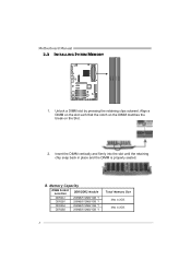
Max is properly seated. Insert the DIMM vertically and firmly into the slot until the retaining chip snap back in place and the DIMM is 2GB. 8 B. Align a DIMM on the slot such that the notch on the DIMM matches the break on the Slot. 2. Memory Capacity DIMM Socket Location DDR/DDR2 Module DDR2A1 256MB/512MB/1GB *1 DDR2B1 256MB/512MB/1GB *1 DDR2A2 256MB/512MB/1GB *1 DDR2B2 256MB/512MB/1GB *1 Total Memory Size Max is 2GB. Motherboard Manual 2.3 INSTALLING SYSTEM MEMORY DDR2A1 DDR2B1 DDR2A2 DDR2B2 1. Unlock a DIMM slot by pressing the retaining clips outward.
Max is properly seated. Insert the DIMM vertically and firmly into the slot until the retaining chip snap back in place and the DIMM is 2GB. 8 B. Align a DIMM on the slot such that the notch on the DIMM matches the break on the Slot. 2. Memory Capacity DIMM Socket Location DDR/DDR2 Module DDR2A1 256MB/512MB/1GB *1 DDR2B1 256MB/512MB/1GB *1 DDR2A2 256MB/512MB/1GB *1 DDR2B2 256MB/512MB/1GB *1 Total Memory Size Max is 2GB. Motherboard Manual 2.3 INSTALLING SYSTEM MEMORY DDR2A1 DDR2B1 DDR2A2 DDR2B2 1. Unlock a DIMM slot by pressing the retaining clips outward.
TForce 550 user's manual
Page 11
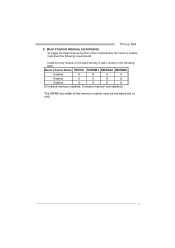
Duual Channel Status DDR2A1 DDR2B1 DDR2A2 DDR2B2 Enabled O O X X Enabled X X O O Enabled O O O O (O means memory installed, X means memory not installed.) The DRAM bus width of the memory module must meet the following table. TForce 550 C. Dual Channel Memory installation To trigger the Dual Channel function of the same density in pairs, shown in the following requirements: Install memory module of the motherboard, the memory module must be the same (x8 or x16) 9
Duual Channel Status DDR2A1 DDR2B1 DDR2A2 DDR2B2 Enabled O O X X Enabled X X O O Enabled O O O O (O means memory installed, X means memory not installed.) The DRAM bus width of the memory module must meet the following table. TForce 550 C. Dual Channel Memory installation To trigger the Dual Channel function of the same density in pairs, shown in the following requirements: Install memory module of the motherboard, the memory module must be the same (x8 or x16) 9

TForce 550 user's manual
Page 12
...up to IDE1. The first hard drive should always be connected to four hard disk drives. IDE1 40 39 2 1 10 Motherboard Manual 2.4 CONNECTORS AND SLOTS FDD1: Floppy Disk Connector The motherboard provides a standard floppy disk connector that provides PIO Mode 0~4, Bus Master, and Ultra DMA 33/66/100/133 functionality. ...This connector supports the provided floppy drive ribbon cables. 34 33 2 1 IDE1: Hard Disk Connectors The motherboard has a 32-bit Enhanced PCI IDE Controller that supports 360K, 720K, 1.2M, 1.44M and 2.88M floppy disk types.
...up to IDE1. The first hard drive should always be connected to four hard disk drives. IDE1 40 39 2 1 10 Motherboard Manual 2.4 CONNECTORS AND SLOTS FDD1: Floppy Disk Connector The motherboard provides a standard floppy disk connector that provides PIO Mode 0~4, Bus Master, and Ultra DMA 33/66/100/133 functionality. ...This connector supports the provided floppy drive ribbon cables. 34 33 2 1 IDE1: Hard Disk Connectors The motherboard has a 32-bit Enhanced PCI IDE Controller that supports 360K, 720K, 1.2M, 1.44M and 2.88M floppy disk types.
TForce 550 user's manual
Page 13
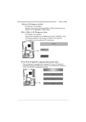
... to 250MB/s per direction, for Peripheral Component Interconnect, and it is designated as 32 bits. PEX16-1 PEX1_1 PEX1_2 PCI1~PCI4: Peripheral Component Interconnect Slots This motherboard is equipped with 4 standard PCI slots. TForce 550 PEx16-1: PCI-Express x16 Slot -
... to 250MB/s per direction, for Peripheral Component Interconnect, and it is designated as 32 bits. PEX16-1 PEX1_1 PEX1_2 PCI1~PCI4: Peripheral Component Interconnect Slots This motherboard is equipped with 4 standard PCI slots. TForce 550 PEx16-1: PCI-Express x16 Slot -
TForce 550 user's manual
Page 14
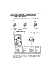
...-on pins, the jumper is "close", if not, that means the jumper is placed on , Reset, HDD LED, Power LED, Sleep button and speaker connection. Motherboard Manual CHAPTER 3: HEADERS & JUMPERS SETUP 3.1 HOW TO SETUP JUMPERS The illustration shows how to connect the PC case's front panel switch functions. 12 It allows...
...-on pins, the jumper is "close", if not, that means the jumper is placed on , Reset, HDD LED, Power LED, Sleep button and speaker connection. Motherboard Manual CHAPTER 3: HEADERS & JUMPERS SETUP 3.1 HOW TO SETUP JUMPERS The illustration shows how to connect the PC case's front panel switch functions. 12 It allows...
TForce 550 user's manual
Page 16
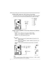
...+ 6 USB+ 7 Ground 8 Ground 9 Key JUSBV1/JUSBV2/JKBMSV1: Power Source Headers for USB Ports Pin 1-2 Close: JUSBV1: +5V for USB ports at front panel (JUSB1/JUSB2). Motherboard Manual JUSB1/JUSB2: Headers for USB 2.0 Ports at Front Panel This header allows user to support this function "Power-On system via USB device," "JUSBV1...
...+ 6 USB+ 7 Ground 8 Ground 9 Key JUSBV1/JUSBV2/JKBMSV1: Power Source Headers for USB Ports Pin 1-2 Close: JUSBV1: +5V for USB ports at front panel (JUSB1/JUSB2). Motherboard Manual JUSB1/JUSB2: Headers for USB 2.0 Ports at Front Panel This header allows user to support this function "Power-On system via USB device," "JUSBV1...
TForce 550 user's manual
Page 18
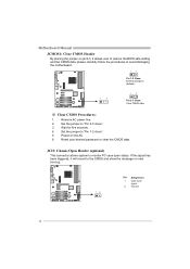
... placing the jumper on pin2-3, it will record to the CMOS and show the message on the AC. 6. Set the jumper to avoid damaging the motherboard. 13 Pin 1-2 Close: Normal Operation (default). 1 3 13 Pin 2-3 Close: Clear CMOS data. ※ Clear CMOS Procedures: 1. Power on next boot-up. 12 Pin Assignment 1 Case...
... placing the jumper on pin2-3, it will record to the CMOS and show the message on the AC. 6. Set the jumper to avoid damaging the motherboard. 13 Pin 1-2 Close: Normal Operation (default). 1 3 13 Pin 2-3 Close: Clear CMOS data. ※ Clear CMOS Procedures: 1. Power on next boot-up. 12 Pin Assignment 1 Case...
TForce 550 user's manual
Page 19
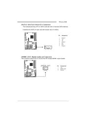
TForce 550 JSATA1~JSATA4: Serial ATA Connectors The motherboard has a PCI to SATA Controller with 2 channels SATA interface, it satisfies the SATA 2.0 spec and with transfer rate of 3.0Gb/s. 14 7 Pin Assignment 1 Ground 2 TX+ 3 TX4 Ground 5 RX6 RX+ 7 Ground JSPDIF_OUT: Digital Audio out Connectors This connector allows user to connect the PCI bracket SPDIF output header. JSPDIF_OUT 13 Pin Assignment 1 +5V 2 SPDIF_OUT 3 Ground 17
TForce 550 JSATA1~JSATA4: Serial ATA Connectors The motherboard has a PCI to SATA Controller with 2 channels SATA interface, it satisfies the SATA 2.0 spec and with transfer rate of 3.0Gb/s. 14 7 Pin Assignment 1 Ground 2 TX+ 3 TX4 Ground 5 RX6 RX+ 7 Ground JSPDIF_OUT: Digital Audio out Connectors This connector allows user to connect the PCI bracket SPDIF output header. JSPDIF_OUT 13 Pin Assignment 1 +5V 2 SPDIF_OUT 3 Ground 17

TForce 550 user's manual
Page 20
Motherboard Manual JPRNT1: Printer Port Connector This header allows you to connector printer on the PC. 2 1 25 Pin Assignment 1 -Strobe 2 -ALF 3 Data 0 4 -Error 5 Data 1 6 -Init 7 Data 2 8 -Scltin 9 Data 3 10 Ground 11 Data 4 12 Ground 13 Data 5 Pin Assignment 14 Ground 15 Data 6 16 Ground 17 Data 7 18 Ground 19 -ACK 20 Ground 21 Busy 22 Ground 23 PE 24 Ground 25 SCLT 18
Motherboard Manual JPRNT1: Printer Port Connector This header allows you to connector printer on the PC. 2 1 25 Pin Assignment 1 -Strobe 2 -ALF 3 Data 0 4 -Error 5 Data 1 6 -Init 7 Data 2 8 -Scltin 9 Data 3 10 Ground 11 Data 4 12 Ground 13 Data 5 Pin Assignment 14 Ground 15 Data 6 16 Ground 17 Data 7 18 Ground 19 -ACK 20 Ground 21 Busy 22 Ground 23 PE 24 Ground 25 SCLT 18
TForce 550 user's manual
Page 22
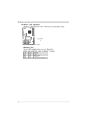
LED1 LED2 LED1 and LED2: These 2 LED indicate system power on the motherboard to the table below for different messages: LED1 ON ON OFF OFF LED2 ON OFF ON OFF Message Normal Memory Error VGA Error Abnormal: CPU / Chipset error. 20 Motherboard Manual On-Board LED Indicators There are 2 LED indicators on diagnostics. Please refer to show system status.
LED1 LED2 LED1 and LED2: These 2 LED indicate system power on the motherboard to the table below for different messages: LED1 ON ON OFF OFF LED2 ON OFF ON OFF Message Normal Memory Error VGA Error Abnormal: CPU / Chipset error. 20 Motherboard Manual On-Board LED Indicators There are 2 LED indicators on diagnostics. Please refer to show system status.
TForce 550 user's manual
Page 24
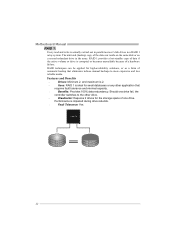
... volume or drive is corrupted or becomes unavailable because of automatic backup that requires fault tolerance and minimal capacity. Benefits: Provides 100% data redundancy. Motherboard Manual RAID 1: Every read and write is actually carried out in parallel across 2 disk drives in the array. The mirrored (backup) copy of the data...
... volume or drive is corrupted or becomes unavailable because of automatic backup that requires fault tolerance and minimal capacity. Benefits: Provides 100% data redundancy. Motherboard Manual RAID 1: Every read and write is actually carried out in parallel across 2 disk drives in the array. The mirrored (backup) copy of the data...
TForce 550 user's manual
Page 26
... (M.I.T., under Overclock Navigator Engine) Integrated Flash Program (I.F.P.) Smart Fan Function (under BIOS or Windows interface, T-Power is designed for overclock users. Motherboard Manual CHAPTER 5: OVERCLOCK QUICK GUIDE 5.1: T-POWER INTRODUCTION Biostar T-Power is a whole new utility that is able to present the best system state according to raise system performance. No matter whether...
... (M.I.T., under Overclock Navigator Engine) Integrated Flash Program (I.F.P.) Smart Fan Function (under BIOS or Windows interface, T-Power is designed for overclock users. Motherboard Manual CHAPTER 5: OVERCLOCK QUICK GUIDE 5.1: T-POWER INTRODUCTION Biostar T-Power is a whole new utility that is able to present the best system state according to raise system performance. No matter whether...
TForce 550 user's manual
Page 28
... the system stability, CPU voltage needs to system performance. PCI-Express Overclock Setting: PCIE Clock: It helps to set this item at "x4" when overclocking. Motherboard Manual CPU Overclock Setting: CPU Voltage: This function will increase chipset stability when overclocking. Chipset Overclock Setting: NB/SB Voltage Regulator: This function will increase...
... the system stability, CPU voltage needs to system performance. PCI-Express Overclock Setting: PCIE Clock: It helps to set this item at "x4" when overclocking. Motherboard Manual CPU Overclock Setting: CPU Voltage: This function will increase chipset stability when overclocking. Chipset Overclock Setting: NB/SB Voltage Regulator: This function will increase...

TForce 550 user's manual
Page 30
... 50 sets of record addresses in total, and users are able to name the CMOS data according to reload any saved CMOS setting for this A.O.S. Motherboard Manual V12 Tech Engine: This setting will be based on the selected CPU model. 2. Notices: 1. Not all types of whole system performance. feature. Users are...
... 50 sets of record addresses in total, and users are able to name the CMOS data according to reload any saved CMOS setting for this A.O.S. Motherboard Manual V12 Tech Engine: This setting will be based on the selected CPU model. 2. Notices: 1. Not all types of whole system performance. feature. Users are...
TForce 550 user's manual
Page 32
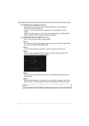
... System (S.R.S.): This function can update the system BIOS by simply pressing "Enter" key for three times. 30 E. Step 1: Go to Biostar website (http://www.biostar.com.tw) to get into a floppy disk. Step 3: Select the item "Integrated Flash Program" to download the latest BIOS file. When... frame and choose the BIOS file downloaded in the default BIOS setting, and all overclock settings will reboot automatically to finish the process. Motherboard Manual D. Then, save the file into CMOS screen. Step 2: Insert the floppy disk and reboot the system to upgrade BIOS. will...
... System (S.R.S.): This function can update the system BIOS by simply pressing "Enter" key for three times. 30 E. Step 1: Go to Biostar website (http://www.biostar.com.tw) to get into a floppy disk. Step 3: Select the item "Integrated Flash Program" to download the latest BIOS file. When... frame and choose the BIOS file downloaded in the default BIOS setting, and all overclock settings will reboot automatically to finish the process. Motherboard Manual D. Then, save the file into CMOS screen. Step 2: Insert the floppy disk and reboot the system to upgrade BIOS. will...

