Setup Manual
Page 7
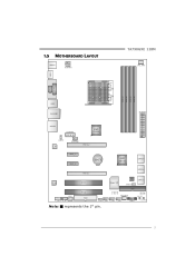
1.5 MOTHERBOARD LAYOUT KBMS 1 ATXPWR1 TA790GXE 128M CPU_ FAN1 HDMI1 S ocket A M 2+ DVI VG A PH1 PH2 PH3 PH4 DIMM A1 DIMM B1 DIMM A2 DIMM B2 USB1 RJ4 5USB1 ATXPWR2 AUDIO2 AUXPWR1 AMD 790GX JUSBV1 L AN SYS_FAN1 PEX16_ 2 PEX1 _1 PEX1 _2 BAT1 AMD SB750 SATA5-6 PEX16_ 1 SATA3-4 Co de c PCI1 Super I/O BI O S JCMOS1 SATA1-2 S PDIF1 F_AUDIO1 CD_IN1 PCI2 FDD1 IDE1 SYS_FA N2 LED_D1 LED_D2 SW_ RST JUSBV 2 F_USB 3 F_USB2 F_USB 1 PANEL1 SW_P WR Note: ■ represents the 1st pin. 5
1.5 MOTHERBOARD LAYOUT KBMS 1 ATXPWR1 TA790GXE 128M CPU_ FAN1 HDMI1 S ocket A M 2+ DVI VG A PH1 PH2 PH3 PH4 DIMM A1 DIMM B1 DIMM A2 DIMM B2 USB1 RJ4 5USB1 ATXPWR2 AUDIO2 AUXPWR1 AMD 790GX JUSBV1 L AN SYS_FAN1 PEX16_ 2 PEX1 _1 PEX1 _2 BAT1 AMD SB750 SATA5-6 PEX16_ 1 SATA3-4 Co de c PCI1 Super I/O BI O S JCMOS1 SATA1-2 S PDIF1 F_AUDIO1 CD_IN1 PCI2 FDD1 IDE1 SYS_FA N2 LED_D1 LED_D2 SW_ RST JUSBV 2 F_USB 3 F_USB2 F_USB 1 PANEL1 SW_P WR Note: ■ represents the 1st pin. 5
Setup Manual
Page 11
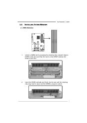
2.3 INSTALLING SYSTEM MEMORY A. DDR2 Modules TA790GXE 128M D IM M A1 D IM M B1 D IM M A2 D IM M B2 1. Align a DIMM on the slot such that the notch on the DIMM matches the break on the Slot. 2. Unlock a DIMM slot by pressing the retaining clips outward. Insert the DIMM vertically and firmly into the slot until the retaining chip snap back in place and the DIMM is properly seated. 9
2.3 INSTALLING SYSTEM MEMORY A. DDR2 Modules TA790GXE 128M D IM M A1 D IM M B1 D IM M A2 D IM M B2 1. Align a DIMM on the slot such that the notch on the DIMM matches the break on the Slot. 2. Unlock a DIMM slot by pressing the retaining clips outward. Insert the DIMM vertically and firmly into the slot until the retaining chip snap back in place and the DIMM is properly seated. 9
