
Setup Manual
Page 2
... 1: Introduction 1 1.1 Before You Start 1 1.2 Package Checklist 1 1.3 Motherboard Features 2 1.4 Rear Panel Connectors 4 1.5 Motherboard Layout 5 Chapter 2: Hardware Installation 6 2.1 Installing Central Processing Unit (CPU 6 2.2 FAN Headers 8 2.3 Installing System Memory 9 2.4 Connectors and Slots 11 Chapter 3: Headers & Jumpers Setup 14 3.1 How to Setup Jumpers 14 3.2 Detail Settings 14 Chapter 4: (Hybrid) CrossFireX Function 22 4.1 CrossFireX Requirements 22...
... 1: Introduction 1 1.1 Before You Start 1 1.2 Package Checklist 1 1.3 Motherboard Features 2 1.4 Rear Panel Connectors 4 1.5 Motherboard Layout 5 Chapter 2: Hardware Installation 6 2.1 Installing Central Processing Unit (CPU 6 2.2 FAN Headers 8 2.3 Installing System Memory 9 2.4 Connectors and Slots 11 Chapter 3: Headers & Jumpers Setup 14 3.1 How to Setup Jumpers 14 3.2 Detail Settings 14 Chapter 4: (Hybrid) CrossFireX Function 22 4.1 CrossFireX Requirements 22...
Setup Manual
Page 4
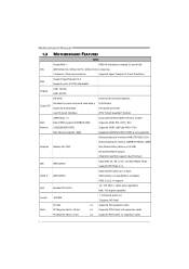
.../2GB/4GB DDR2 Supports DDR2 1066 (by AM2+ CPU) Max Memory Capicity 16GB Registered DIMM and ECC DIMM is not supported Onboard side port memory 64MB (TA790GX A2+) Onboard side port memory 128MB (TA790GX 128M) Graphics Radeon HD 3300 Max Shared Video Memory is 512MB DX10/UVD/HDCP support (Hybrid) CrossFireX support (by ATI driver) IDE AMD...
.../2GB/4GB DDR2 Supports DDR2 1066 (by AM2+ CPU) Max Memory Capicity 16GB Registered DIMM and ECC DIMM is not supported Onboard side port memory 64MB (TA790GX A2+) Onboard side port memory 128MB (TA790GX 128M) Graphics Radeon HD 3300 Max Shared Video Memory is 512MB DX10/UVD/HDCP support (Hybrid) CrossFireX support (by ATI driver) IDE AMD...

Setup Manual
Page 11
Insert the DIMM vertically and firmly into the slot until the retaining chip snap back in place and the DIMM is properly seated. 9 Unlock a DIMM slot by pressing the retaining clips outward. DIMMA 1 DIMMB 1 DIMMA 2 DIMMB 2 TA790GX A2+/TA790GX A2+ SE/TA790GX 128M 2.3 INSTALLING SYSTEM MEMORY A. Align a DIMM on the slot such that the notch on the DIMM matches the break on the Slot. 2. DDR2 Modules 1.
Insert the DIMM vertically and firmly into the slot until the retaining chip snap back in place and the DIMM is properly seated. 9 Unlock a DIMM slot by pressing the retaining clips outward. DIMMA 1 DIMMB 1 DIMMA 2 DIMMB 2 TA790GX A2+/TA790GX A2+ SE/TA790GX 128M 2.3 INSTALLING SYSTEM MEMORY A. Align a DIMM on the slot such that the notch on the DIMM matches the break on the Slot. 2. DDR2 Modules 1.

Setup Manual
Page 12
... X Enabled X X O O Enabled O O O O (O means memory installed, X means memory not installed.) The DRAM bus width of the memory module must meet the following requirements: Install memory module of the motherboard, the memory module must be the same (x8 or x16) 10 Dual Channel Memory installation To trigger the Dual Channel function of the... same density in pairs, shown in the following table. Motherboard Manual B. Memory Capacity DIMM Socket Location DIMMA1 DIMMB1 DIMMA2 DIMMB2 DDR2 Module 256MB/512MB/1GB/2GB/4GB 256MB/512MB/1GB/2GB/...
... X Enabled X X O O Enabled O O O O (O means memory installed, X means memory not installed.) The DRAM bus width of the memory module must meet the following requirements: Install memory module of the motherboard, the memory module must be the same (x8 or x16) 10 Dual Channel Memory installation To trigger the Dual Channel function of the... same density in pairs, shown in the following table. Motherboard Manual B. Memory Capacity DIMM Socket Location DIMMA1 DIMMB1 DIMMA2 DIMMB2 DDR2 Module 256MB/512MB/1GB/2GB/4GB 256MB/512MB/1GB/2GB/...

Setup Manual
Page 23
TA790GX A2+/TA790GX A2+ SE/TA790GX 128M On-Board LED Indicators There are 2 on-board buttons. RSTSW1 PWRSW1 PWRSW1: This is an on -board Power Switch button. RSTSW1: This is an on -board Reset button. 21 Memory Error VGA Error Normal On-Board Buttons There are 2 LED indicators on diagnostics. Please refer to show system status. LED_D1 LED_D2 LED_D1 and LED_D2: These 2 LED indicate system power on the motherboard to the table below for different messages: LED_D2 OFF OFF ON ON LED_D1 OFF ON OFF ON Message Abnormal: CPU / Chipset error.
TA790GX A2+/TA790GX A2+ SE/TA790GX 128M On-Board LED Indicators There are 2 on-board buttons. RSTSW1 PWRSW1 PWRSW1: This is an on -board Power Switch button. RSTSW1: This is an on -board Reset button. 21 Memory Error VGA Error Normal On-Board Buttons There are 2 LED indicators on diagnostics. Please refer to show system status. LED_D1 LED_D2 LED_D1 and LED_D2: These 2 LED indicate system power on the motherboard to the table below for different messages: LED_D2 OFF OFF ON ON LED_D1 OFF ON OFF ON Message Abnormal: CPU / Chipset error.
Setup Manual
Page 31
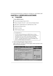
... [1.20V] CPU Frequency [200] > CPU FID/VID Control > DRAM Timing Configuration > Hyper Transport Configuration > Memory Configuration Integrated Memory Test [Disabled] Normal Automate OverClock Manual OverClock Select Screen Select Item +- For better system performance, the BIOS firmware...may cause system to the BIOS Manual in this manual. TA790GX A2+/TA790GX A2+ SE/TA790GX 128M CHAPTER 6: T-SERIES BIOS & SOFTWARE 6.1 T-SERIES BIOS T-Series BIOS Features Overclocking Navigator Engine (O.N.E.) Memory Integration Test (M.I.T., under Overclock Navigator Engine) BIO-Flasher: ...
... [1.20V] CPU Frequency [200] > CPU FID/VID Control > DRAM Timing Configuration > Hyper Transport Configuration > Memory Configuration Integrated Memory Test [Disabled] Normal Automate OverClock Manual OverClock Select Screen Select Item +- For better system performance, the BIOS firmware...may cause system to the BIOS Manual in this manual. TA790GX A2+/TA790GX A2+ SE/TA790GX 128M CHAPTER 6: T-SERIES BIOS & SOFTWARE 6.1 T-SERIES BIOS T-Series BIOS Features Overclocking Navigator Engine (O.N.E.) Memory Integration Test (M.I.T., under Overclock Navigator Engine) BIO-Flasher: ...

Setup Manual
Page 32
... system to malfunction. However, the CPU temperature will increase CPU stability when overclocking the HT ratio. 30 Memory Overvoltage This function will increase CPU stability when overclocking. OverClock Navigator [Normal] =========== Automate OverClock System =========== ... [1.20V] CPU Frequency [200] > CPU FID/VID Control > DRAM Timing Configuration > Hyper Transport Configuration > Memory Configuration Integrated Memory Test [Disabled] Normal Automate OverClock Manual OverClock Select Screen Select Item +- Chipset Overvoltage This function will increase Northbridge ...
... system to malfunction. However, the CPU temperature will increase CPU stability when overclocking the HT ratio. 30 Memory Overvoltage This function will increase CPU stability when overclocking. OverClock Navigator [Normal] =========== Automate OverClock System =========== ... [1.20V] CPU Frequency [200] > CPU FID/VID Control > DRAM Timing Configuration > Hyper Transport Configuration > Memory Configuration Integrated Memory Test [Disabled] Normal Automate OverClock Manual OverClock Select Screen Select Item +- Chipset Overvoltage This function will increase Northbridge ...
Setup Manual
Page 33
... 31 NOTE Overclock is directly in overclock field, BET had developed an easy, fast, and powerful feature to malfunction. TA790GX A2+/TA790GX A2+ SE/TA790GX 128M CPU Frequency CPU Frequency is an optional process, but not a "must-do" process; Main Advanced PCIPnP BIOS ... Voltage [1.20V] CPU Frequency [200] > CPU FID/VID Control > DRAM Timing Configuration > Hyper Transport Configuration > Memory Configuration Integrated Memory Test [Disabled] Normal Automate OverClock Manual OverClock Select Screen Select Item +- it is not recommended for more advanced Hyper ...
... 31 NOTE Overclock is directly in overclock field, BET had developed an easy, fast, and powerful feature to malfunction. TA790GX A2+/TA790GX A2+ SE/TA790GX 128M CPU Frequency CPU Frequency is an optional process, but not a "must-do" process; Main Advanced PCIPnP BIOS ... Voltage [1.20V] CPU Frequency [200] > CPU FID/VID Control > DRAM Timing Configuration > Hyper Transport Configuration > Memory Configuration Integrated Memory Test [Disabled] Normal Automate OverClock Manual OverClock Select Screen Select Item +- it is not recommended for more advanced Hyper ...

Setup Manual
Page 34
... Over Voltage [1.20V] CPU Frequency [200] > CPU FID/VID Control > DRAM Timing Configuration > Hyper Transport Configuration > Memory Configuration Integrated Memory Test [Disabled] V6-Tech Engine V8-Tech Engine V12-Tech Engine Select Screen Select Item +- OverClock Navigator [Automate OverClock] ...Voltage [1.20V] CPU Frequency [200] > CPU FID/VID Control > DRAM Timing Configuration > Hyper Transport Configuration > Memory Configuration Integrated Memory Test [Disabled] V6-Tech Engine V8-Tech Engine V12-Tech Engine Select Screen Select Item +- Main Advanced PCIPnP BIOS ...
... Over Voltage [1.20V] CPU Frequency [200] > CPU FID/VID Control > DRAM Timing Configuration > Hyper Transport Configuration > Memory Configuration Integrated Memory Test [Disabled] V6-Tech Engine V8-Tech Engine V12-Tech Engine Select Screen Select Item +- OverClock Navigator [Automate OverClock] ...Voltage [1.20V] CPU Frequency [200] > CPU FID/VID Control > DRAM Timing Configuration > Hyper Transport Configuration > Memory Configuration Integrated Memory Test [Disabled] V6-Tech Engine V8-Tech Engine V12-Tech Engine Select Screen Select Item +- Main Advanced PCIPnP BIOS ...
Setup Manual
Page 35
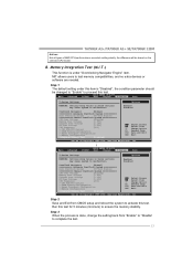
... [1.20V] CPU Frequency [200] > CPU FID/VID Control > DRAM Timing Configuration > Hyper Transport Configuration > Memory Configuration Integrated Memory Test [Disabled] Select Screen Select Item +- Enabled Disabled OverClock Navigator [Normal] =========== Automate OverClock System =========== Auto...> CPU FID/VID Control > DRAM Timing Configuration > Hyper Transport Configuration > Memory Configuration Integrated Memory Test [Enabled] Select Screen Select Item +- TA790GX A2+/TA790GX A2+ SE/TA790GX 128M Notices: Not all types of AMD CPU perform above overclock setting ideally...
... [1.20V] CPU Frequency [200] > CPU FID/VID Control > DRAM Timing Configuration > Hyper Transport Configuration > Memory Configuration Integrated Memory Test [Disabled] Select Screen Select Item +- Enabled Disabled OverClock Navigator [Normal] =========== Automate OverClock System =========== Auto...> CPU FID/VID Control > DRAM Timing Configuration > Hyper Transport Configuration > Memory Configuration Integrated Memory Test [Enabled] Select Screen Select Item +- TA790GX A2+/TA790GX A2+ SE/TA790GX 128M Notices: Not all types of AMD CPU perform above overclock setting ideally...
Setup Manual
Page 39
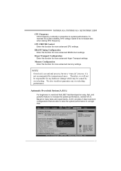
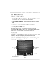
TA790GX A2+/TA790GX A2+ SE/TA790GX 128M 6.2 T-SERIES SOFTWARE Installing T-Series Software 1. Launching T-Series Software After the installation process, you will see current CPU Speed and CPU/Memory/PCI-E/PCI Clock. In this panel you easily do over -clock features, and it will see the software icon "T-Utility OverClock III" / "HW Monitor" / "eHOT ...
TA790GX A2+/TA790GX A2+ SE/TA790GX 128M 6.2 T-SERIES SOFTWARE Installing T-Series Software 1. Launching T-Series Software After the installation process, you will see current CPU Speed and CPU/Memory/PCI-E/PCI Clock. In this panel you easily do over -clock features, and it will see the software icon "T-Utility OverClock III" / "HW Monitor" / "eHOT ...

Setup Manual
Page 42
... function allows user to adjust Chipset voltage. Chip Voltage This function allows user to adjust Memory voltage. Click on "+" to increase or "-" to decrease the Chipset voltage. Click on "+" to increase or "-" to decrease the CPU voltage. FSB Voltage This function... allows user to adjust CPU voltage. Click on "+" to increase or "-" to decrease the FSB voltage. 40 Click on "+" to increase or "-" to decrease the Memory voltage. Motherboard Manual Over Voltage Panel Manual Adjust CPU/Memo ry/Chipset/FSB Voltage CPU Voltage This function allows user to adjust FSB voltage.
... function allows user to adjust Chipset voltage. Chip Voltage This function allows user to adjust Memory voltage. Click on "+" to increase or "-" to decrease the Chipset voltage. Click on "+" to increase or "-" to decrease the CPU voltage. FSB Voltage This function... allows user to adjust CPU voltage. Click on "+" to increase or "-" to decrease the FSB voltage. 40 Click on "+" to increase or "-" to decrease the Memory voltage. Motherboard Manual Over Voltage Panel Manual Adjust CPU/Memo ry/Chipset/FSB Voltage CPU Voltage This function allows user to adjust FSB voltage.

Setup Manual
Page 44
.... Motherboard Manual eHot-Line (Optional) eHot-Line is useful for your confirmation; Send th e mail ou t. Exit this information to . *Provid e the name of the memory module ma nufa ct u rer. If you would like to send t he copy to a .txt file, click "Save As..." This block will see a saving dialog...
.... Motherboard Manual eHot-Line (Optional) eHot-Line is useful for your confirmation; Send th e mail ou t. Exit this information to . *Provid e the name of the memory module ma nufa ct u rer. If you would like to send t he copy to a .txt file, click "Save As..." This block will see a saving dialog...

Setup Manual
Page 51
... of interference by a malfunctioning add-in flash device) POST BIOS Beep Codes Number of Beeps Description 1 Memory refresh timer error 3 Base memory read error 7 No Flash EPROM detected 10 Flash Erase error 11 Flash Program error 12 "AMIBOOT.ROM"...cards are absent, consult your system manufacturer. Consult your system manufacturer's technical support. If the video adapter is causing the malfunction. TA790GX A2+/TA790GX A2+ SE/TA790GX 128M 7.3 AMI BIOS BEEP CODE Boot Block Beep Codes Number of Beeps Description 1 No media present. (Insert diskette in floppy ...
... of interference by a malfunctioning add-in flash device) POST BIOS Beep Codes Number of Beeps Description 1 Memory refresh timer error 3 Base memory read error 7 No Flash EPROM detected 10 Flash Erase error 11 Flash Program error 12 "AMIBOOT.ROM"...cards are absent, consult your system manufacturer. Consult your system manufacturer's technical support. If the video adapter is causing the malfunction. TA790GX A2+/TA790GX A2+ SE/TA790GX 128M 7.3 AMI BIOS BEEP CODE Boot Block Beep Codes Number of Beeps Description 1 No media present. (Insert diskette in floppy ...
Setup Manual
Page 70
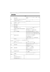
... DDR2 533 / 667 / 800 DDR2 1066 by AM2+ CPU) 16GB 登録済みDIMMとECC DIMM Onboard side port memory 64MB (TA790GX A2+) Radeon HD 3300 ス Onboard side port memory 128MB (TA790GX 128M 512MBです DX10/UVD/HDCP (Hybrid) CrossFireX by ATI driver) ITE 8718 Super I/O機 H/Wモニター...
... DDR2 533 / 667 / 800 DDR2 1066 by AM2+ CPU) 16GB 登録済みDIMMとECC DIMM Onboard side port memory 64MB (TA790GX A2+) Radeon HD 3300 ス Onboard side port memory 128MB (TA790GX 128M 512MBです DX10/UVD/HDCP (Hybrid) CrossFireX by ATI driver) ITE 8718 Super I/O機 H/Wモニター...

Bios Setup
Page 4
...BIOS SETU P U TILITY PCIPnP Boot Chipset T-Series Exit System Overvie w AMI BIOS Version :01. 01.01 Build Date:01/ 01/08 System Memory Size : Use [ENTER], [TAB] or [SHIFT-TAB] to configure system Time. AMI BIOS Shows system information, including BIOS version and built ... the system internal clock. System Memory Shows system memory size. C hange Field Tab S elect Field F1 G eneral Help F10 S ave and Exit ESC E xit vxx .xx (C)Copyright 1985-200x, American Me gatrends, Inc. System Date Set the system date. TA790GX A2+/TA790GX A2+ SE/TA790GX 128M BIOS Manual 1 Main Menu...
...BIOS SETU P U TILITY PCIPnP Boot Chipset T-Series Exit System Overvie w AMI BIOS Version :01. 01.01 Build Date:01/ 01/08 System Memory Size : Use [ENTER], [TAB] or [SHIFT-TAB] to configure system Time. AMI BIOS Shows system information, including BIOS version and built ... the system internal clock. System Memory Shows system memory size. C hange Field Tab S elect Field F1 G eneral Help F10 S ave and Exit ESC E xit vxx .xx (C)Copyright 1985-200x, American Me gatrends, Inc. System Date Set the system date. TA790GX A2+/TA790GX A2+ SE/TA790GX 128M BIOS Manual 1 Main Menu...

Bios Setup
Page 9
...S ave and Exit ESC E xit vxx .xx (C)Copyright 1985-200x, American Me gatrends, Inc. Options: Enabled (Default) / Disabled 8 TA790GX A2+/TA790GX A2+ SE/TA790GX 128M BIOS Manual Secure Virtual Machine Mode Virtualization T echnology can virtually separate your system has a floppy disk controller (FDC) installed on AC Power ...item controls whether the SRAT is made available to the operating system at boot time and uses the information to better allocate memory and schedule software threads for maximum perform ance. T his item allows you installed another FDC or the system uses no ...
...S ave and Exit ESC E xit vxx .xx (C)Copyright 1985-200x, American Me gatrends, Inc. Options: Enabled (Default) / Disabled 8 TA790GX A2+/TA790GX A2+ SE/TA790GX 128M BIOS Manual Secure Virtual Machine Mode Virtualization T echnology can virtually separate your system has a floppy disk controller (FDC) installed on AC Power ...item controls whether the SRAT is made available to the operating system at boot time and uses the information to better allocate memory and schedule software threads for maximum perform ance. T his item allows you installed another FDC or the system uses no ...

Bios Setup
Page 18
... 17 This item allows such snooping to take place. DMA Channel 0 DMA Channel 1 DMA Channel 3 DMA Channel 5 DMA Channel 6 DMA Channel 7 Reserved Memory Size [Available] [Available] [Available] [Available] [Available] [Available] [Disabled] Select Screen Select Item +- Reserved: Specified IRQ is reserved for use by ...) / No Palette Snooping Some old graphic controllers need to " snoop" on the VGA palette and then map it over . TA790GX A2+/TA790GX A2+ SE/TA790GX 128M BIOS Manual PCI Latency Timer T his item controls how long a PCI device can retain control of the bus before another ...
... 17 This item allows such snooping to take place. DMA Channel 0 DMA Channel 1 DMA Channel 3 DMA Channel 5 DMA Channel 6 DMA Channel 7 Reserved Memory Size [Available] [Available] [Available] [Available] [Available] [Available] [Disabled] Select Screen Select Item +- Reserved: Specified IRQ is reserved for use by ...) / No Palette Snooping Some old graphic controllers need to " snoop" on the VGA palette and then map it over . TA790GX A2+/TA790GX A2+ SE/TA790GX 128M BIOS Manual PCI Latency Timer T his item controls how long a PCI device can retain control of the bus before another ...

Bios Setup
Page 19
... a type, depending on the type of device using the interrupt. Options: Disabled (Default) / Enabled 18 Options: Available (Default) / Reserved Reserved Memory Size T his item allows BIOS to assign automatically. TA790GX A2+/TA790GX A2+ SE/TA790GX 128M BIOS Manual IRQ3/4/5/7/9/10/11/14/15 T hese items will allow you to assign each system interrupt a type, depending on...
... a type, depending on the type of device using the interrupt. Options: Disabled (Default) / Enabled 18 Options: Available (Default) / Reserved Reserved Memory Size T his item allows BIOS to assign automatically. TA790GX A2+/TA790GX A2+ SE/TA790GX 128M BIOS Manual IRQ3/4/5/7/9/10/11/14/15 T hese items will allow you to assign each system interrupt a type, depending on...

Bios Setup
Page 20
...the screen depends on the number of devices installed in this sub-menu specify the boot device priority sequence from the available devices. Master / Pri. TA790GX A2+/TA790GX A2+ SE/TA790GX 128M BIOS Manual 4 Boot Menu T his menu allows you to Sub Screen F1 G eneral Help F10 S ave and Exit ESC E xit ... Show [Ena bled] AddOn ROM Disp lay Mode [For ce BIOS] Bootup Num-Loc k [ON] Interrupt 19 C apture [Ena bled] Ignore Memory Error Messages [Dis abled] Specifies the Boot Device Priority sequence. Master / Sec. Slave / Sec. Boot De vice Priority Items in the system.
...the screen depends on the number of devices installed in this sub-menu specify the boot device priority sequence from the available devices. Master / Pri. TA790GX A2+/TA790GX A2+ SE/TA790GX 128M BIOS Manual 4 Boot Menu T his menu allows you to Sub Screen F1 G eneral Help F10 S ave and Exit ESC E xit ... Show [Ena bled] AddOn ROM Disp lay Mode [For ce BIOS] Bootup Num-Loc k [ON] Interrupt 19 C apture [Ena bled] Ignore Memory Error Messages [Dis abled] Specifies the Boot Device Priority sequence. Master / Sec. Slave / Sec. Boot De vice Priority Items in the system.


