Setup Manual
Page 4
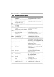
...CPU) Max Memory Capicity 16GB Registered DIMM and ECC DIMM is not supported Onboard side port memory 64MB (TA790GX A2+) Onboard side port memory 128MB (TA790GX 128M) Graphics Radeon HD 3300 Max Shared Video Memory is 512MB DX10/UVD/HDCP support (Hybrid) CrossFireX ...64 X2 computing / Sempron / Phenom processors Supports Hyper Transport 3.0 and PowerNow Support HyperTransport 3.0 FSB Supports up to 5.2 GT/s Bandwidth Chipset AMD 790GX AMD SB750 ITE 8718 Environment Control initiatives, Provides the most commonly used legacy Super I/O Super I/O functionality. SATA II AMD SB750...
...CPU) Max Memory Capicity 16GB Registered DIMM and ECC DIMM is not supported Onboard side port memory 64MB (TA790GX A2+) Onboard side port memory 128MB (TA790GX 128M) Graphics Radeon HD 3300 Max Shared Video Memory is 512MB DX10/UVD/HDCP support (Hybrid) CrossFireX ...64 X2 computing / Sempron / Phenom processors Supports Hyper Transport 3.0 and PowerNow Support HyperTransport 3.0 FSB Supports up to 5.2 GT/s Bandwidth Chipset AMD 790GX AMD SB750 ITE 8718 Environment Control initiatives, Provides the most commonly used legacy Super I/O Super I/O functionality. SATA II AMD SB750...

Setup Manual
Page 6
The chipset uses the same channel to control HDMI and DVI-D, so these two interfaces cannot work at the same time. The DVI-D connector allows digital signals ...
The chipset uses the same channel to control HDMI and DVI-D, so these two interfaces cannot work at the same time. The DVI-D connector allows digital signals ...

Setup Manual
Page 23
RSTSW1 PWRSW1 PWRSW1: This is an on-board Reset button. 21 Please refer to show system status. LED_D1 LED_D2 LED_D1 and LED_D2: These 2 LED indicate system power on -board Power Switch button. RSTSW1: This is an on diagnostics. Memory Error VGA Error Normal On-Board Buttons There are 2 LED indicators on the motherboard to the table below for different messages: LED_D2 OFF OFF ON ON LED_D1 OFF ON OFF ON Message Abnormal: CPU / Chipset error. TA790GX A2+/TA790GX A2+ SE/TA790GX 128M On-Board LED Indicators There are 2 on-board buttons.
RSTSW1 PWRSW1 PWRSW1: This is an on-board Reset button. 21 Please refer to show system status. LED_D1 LED_D2 LED_D1 and LED_D2: These 2 LED indicate system power on -board Power Switch button. RSTSW1: This is an on diagnostics. Memory Error VGA Error Normal On-Board Buttons There are 2 LED indicators on the motherboard to the table below for different messages: LED_D2 OFF OFF ON ON LED_D1 OFF ON OFF ON Message Abnormal: CPU / Chipset error. TA790GX A2+/TA790GX A2+ SE/TA790GX 128M On-Board LED Indicators There are 2 on-board buttons.
Setup Manual
Page 31
... of setting up the BIOS, please refer to malfunction. Main Advanced BIOS SETUP UTILITY PCIPnP Boot Chipset T-Series Exit T-Series Settings Options WARNING: Setting wrong values in below in the Setup CD. ...Over Voltage [1.95V] Chipset Over Voltage [1.15V] HT Over Voltage [1.20V] CPU Frequency [200] > CPU FID/VID Control > DRAM Timing Configuration > Hyper Transport Configuration > Memory Configuration Integrated Memory Test [Disabled] Normal Automate OverClock Manual OverClock Select Screen Select Item +- TA790GX A2+/TA790GX A2+ SE/TA790GX 128M CHAPTER 6: ...
... of setting up the BIOS, please refer to malfunction. Main Advanced BIOS SETUP UTILITY PCIPnP Boot Chipset T-Series Exit T-Series Settings Options WARNING: Setting wrong values in below in the Setup CD. ...Over Voltage [1.95V] Chipset Over Voltage [1.15V] HT Over Voltage [1.20V] CPU Frequency [200] > CPU FID/VID Control > DRAM Timing Configuration > Hyper Transport Configuration > Memory Configuration Integrated Memory Test [Disabled] Normal Automate OverClock Manual OverClock Select Screen Select Item +- TA790GX A2+/TA790GX A2+ SE/TA790GX 128M CHAPTER 6: ...

Setup Manual
Page 32
... Exit vxx.xx (C)Copyright 1985-200x, American Megatrends, Inc. ↓ Main Advanced PCIPnP BIOS SETUP UTILITY Boot Chipset T-Series Exit T-Series Settings Options WARNING: Setting wrong values in below sections may cause system to malfunction. Memory ... Automate OverClock System =========== Auto OverClock System [V6-Tech Engine] Manual OverClock System CPU Over Voltage [StartUp] Memory Over Voltage [1.95V] Chipset Over Voltage [1.15V] HT Over Voltage [1.20V] CPU Frequency [200] > CPU FID/VID Control > DRAM Timing Configuration > Hyper Transport...
... Exit vxx.xx (C)Copyright 1985-200x, American Megatrends, Inc. ↓ Main Advanced PCIPnP BIOS SETUP UTILITY Boot Chipset T-Series Exit T-Series Settings Options WARNING: Setting wrong values in below sections may cause system to malfunction. Memory ... Automate OverClock System =========== Auto OverClock System [V6-Tech Engine] Manual OverClock System CPU Over Voltage [StartUp] Memory Over Voltage [1.95V] Chipset Over Voltage [1.15V] HT Over Voltage [1.20V] CPU Frequency [200] > CPU FID/VID Control > DRAM Timing Configuration > Hyper Transport...
Setup Manual
Page 33
... in below sections may be increased also when raising CPU frequency. Main Advanced PCIPnP BIOS SETUP UTILITY Boot Chipset T-Series Exit T-Series Settings Options WARNING: Setting wrong values in proportion to malfunction. TA790GX A2+/TA790GX A2+ SE/TA790GX 128M CPU Frequency CPU Frequency is not recommended for inexperienced users. We also would not guarantee any hardware...
... in below sections may be increased also when raising CPU frequency. Main Advanced PCIPnP BIOS SETUP UTILITY Boot Chipset T-Series Exit T-Series Settings Options WARNING: Setting wrong values in proportion to malfunction. TA790GX A2+/TA790GX A2+ SE/TA790GX 128M CPU Frequency CPU Frequency is not recommended for inexperienced users. We also would not guarantee any hardware...

Setup Manual
Page 34
...Automate OverClock System =========== Auto OverClock System [V8-Tech Engine] Manual OverClock System CPU Over Voltage [StartUp] Memory Over Voltage [1.95V] Chipset Over Voltage [1.15V] HT Over Voltage [1.20V] CPU Frequency [200] > CPU FID/VID Control > DRAM Timing Configuration > ... OverClock System =========== Auto OverClock System [V12-Tech Engine] Manual OverClock System CPU Over Voltage [StartUp] Memory Over Voltage [1.95V] Chipset Over Voltage [1.15V] HT Over Voltage [1.20V] CPU Frequency [200] > CPU FID/VID Control > DRAM Timing Configuration > Hyper...
...Automate OverClock System =========== Auto OverClock System [V8-Tech Engine] Manual OverClock System CPU Over Voltage [StartUp] Memory Over Voltage [1.95V] Chipset Over Voltage [1.15V] HT Over Voltage [1.20V] CPU Frequency [200] > CPU FID/VID Control > DRAM Timing Configuration > ... OverClock System =========== Auto OverClock System [V12-Tech Engine] Manual OverClock System CPU Over Voltage [StartUp] Memory Over Voltage [1.95V] Chipset Over Voltage [1.15V] HT Over Voltage [1.20V] CPU Frequency [200] > CPU FID/VID Control > DRAM Timing Configuration > Hyper...
Setup Manual
Page 35
...OverClock System =========== Auto OverClock System [V6-Tech Engine] Manual OverClock System CPU Over Voltage [StartUp] Memory Over Voltage [1.95V] Chipset Over Voltage [1.15V] HT Over Voltage [1.20V] CPU Frequency [200] > CPU FID/VID Control > DRAM Timing Configuration >...[1.95V] Chipset Over Voltage [1.15V] HT Over Voltage [1.20V] CPU Frequency [200] > CPU FID/VID Control > DRAM Timing Configuration > Hyper Transport Configuration > Memory Configuration Integrated Memory Test [Disabled] Select Screen Select Item +- TA790GX A2+/TA790GX A2+ SE/TA790GX 128M Notices...
...OverClock System =========== Auto OverClock System [V6-Tech Engine] Manual OverClock System CPU Over Voltage [StartUp] Memory Over Voltage [1.95V] Chipset Over Voltage [1.15V] HT Over Voltage [1.20V] CPU Frequency [200] > CPU FID/VID Control > DRAM Timing Configuration >...[1.95V] Chipset Over Voltage [1.15V] HT Over Voltage [1.20V] CPU Frequency [200] > CPU FID/VID Control > DRAM Timing Configuration > Hyper Transport Configuration > Memory Configuration Integrated Memory Test [Disabled] Select Screen Select Item +- TA790GX A2+/TA790GX A2+ SE/TA790GX 128M Notices...
Setup Manual
Page 37
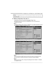
...Smart Fan Function Smart Fan Function is controlled automatically by CPU/System temperature. Main Advanced BIOS SETUP UTILITY PCIPnP Boot Chipset T-Series Exit Advanced Settings WARNING: Setting wrong values in "Advanced Menu". and is a brilliant feature to control ...please run the calibration to inappropriate overclock actions. Self Recovery System (S.R.S.) This function can prevent system hang-up , S.R.S. TA790GX A2+/TA790GX A2+ SE/TA790GX 128M D. will automatically log in the default BIOS setting, and all overclock settings will protect CPU/System from overheat ...
...Smart Fan Function Smart Fan Function is controlled automatically by CPU/System temperature. Main Advanced BIOS SETUP UTILITY PCIPnP Boot Chipset T-Series Exit Advanced Settings WARNING: Setting wrong values in "Advanced Menu". and is a brilliant feature to control ...please run the calibration to inappropriate overclock actions. Self Recovery System (S.R.S.) This function can prevent system hang-up , S.R.S. TA790GX A2+/TA790GX A2+ SE/TA790GX 128M D. will automatically log in the default BIOS setting, and all overclock settings will protect CPU/System from overheat ...

Setup Manual
Page 38
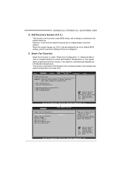
... Exit Options Save Changes and Exit Discard Changes and Exit Discard Changes Load Optimal Defaults CMOS Backup Function Security Settings > Security BIOS SETUP UTILITY Boot Chipset T-Series Exit CMOS Backup Func CMOS Data Reload CMOS Data Save Select Screen Select Item EnterGo to the set value, the CPU/System fan will...
... Exit Options Save Changes and Exit Discard Changes and Exit Discard Changes Load Optimal Defaults CMOS Backup Function Security Settings > Security BIOS SETUP UTILITY Boot Chipset T-Series Exit CMOS Backup Func CMOS Data Reload CMOS Data Save Select Screen Select Item EnterGo to the set value, the CPU/System fan will...

Setup Manual
Page 42
.... Chip Voltage This function allows user to adjust CPU voltage. Click on "+" to increase or "-" to decrease the Chipset voltage. Motherboard Manual Over Voltage Panel Manual Adjust CPU/Memo ry/Chipset/FSB Voltage CPU Voltage This function allows user to adjust Chipset voltage. Click on "+" to increase or "-" to decrease the CPU voltage.
.... Chip Voltage This function allows user to adjust CPU voltage. Click on "+" to increase or "-" to decrease the Chipset voltage. Motherboard Manual Over Voltage Panel Manual Adjust CPU/Memo ry/Chipset/FSB Voltage CPU Voltage This function allows user to adjust Chipset voltage. Click on "+" to increase or "-" to decrease the CPU voltage.

Setup Manual
Page 43
TA790GX A2+/TA790GX A2+ SE/TA790GX 128M About Panel In this software. This property can also get model name and other panels' functions. It provides real-time information of the PC. If one chipset is a monitor utility that may related to over-clocking. Hardware Monitor HW Monitor is not on board, the correlative button in ... shows CPU/System f an speed Turn to separate panels. Note Because the Over Clock and Over Voltage features are controlled by several separate chipset, the utility divides these features to Voltage P anel 41 You can make the utility more robust.
TA790GX A2+/TA790GX A2+ SE/TA790GX 128M About Panel In this software. This property can also get model name and other panels' functions. It provides real-time information of the PC. If one chipset is a monitor utility that may related to over-clocking. Hardware Monitor HW Monitor is not on board, the correlative button in ... shows CPU/System f an speed Turn to separate panels. Note Because the Over Clock and Over Voltage features are controlled by several separate chipset, the utility divides these features to Voltage P anel 41 You can make the utility more robust.

Bios Setup
Page 1
TA790GX A2+/TA790GX A2+ SE/TA790GX 128M BIOS Manual BIOS Setup 1 1 Main Menu 3 2 Advanced Menu 7 3 PCIPnP Menu 16 4 Boot Menu 19 5 Chipset Menu 21 6 T-S eries Menu 30 7 Exit Menu 40 i
TA790GX A2+/TA790GX A2+ SE/TA790GX 128M BIOS Manual BIOS Setup 1 1 Main Menu 3 2 Advanced Menu 7 3 PCIPnP Menu 16 4 Boot Menu 19 5 Chipset Menu 21 6 T-S eries Menu 30 7 Exit Menu 40 i
Bios Setup
Page 2
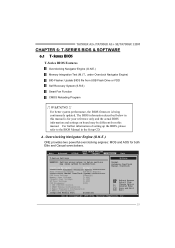
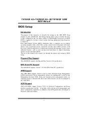
...management features are supported. BIOS activates at the first stag e o f the booting process, loading and executing the operating system. TA790GX A2+/TA790GX A2+ SE/TA790GX 128M BIOS Manual BIOS Setup Introduction T he purpose of this manual is to describe the settings in the AMI BIOS Setup program on... this manual will to guide you through the options and settings in BIOS Setup. Some additional features, such as virus and password prot ection or chipset...
...management features are supported. BIOS activates at the first stag e o f the booting process, loading and executing the operating system. TA790GX A2+/TA790GX A2+ SE/TA790GX 128M BIOS Manual BIOS Setup Introduction T he purpose of this manual is to describe the settings in the AMI BIOS Setup program on... this manual will to guide you through the options and settings in BIOS Setup. Some additional features, such as virus and password prot ection or chipset...

Bios Setup
Page 4
...Shows system information, including BIOS version and built date. System Date Set the system date. Main Advan ced BIOS SETU P U TILITY PCIPnP Boot Chipset T-Series Exit System Overvie w AMI BIOS Version :01. 01.01 Build Date:01/ 01/08 System Memory Size : Use [ENTER], [... [Tue 01/01/2008] S elect Screen S elect Item +- System Memory Shows system memory size. Use [+] or [-] to select a field. TA790GX A2+/TA790GX A2+ SE/TA790GX 128M BIOS Manual 1 Main Menu Once you set the date. 3 System Time Set the system internal clock. Note that the 'Day' automatically changes ...
...Shows system information, including BIOS version and built date. System Date Set the system date. Main Advan ced BIOS SETU P U TILITY PCIPnP Boot Chipset T-Series Exit System Overvie w AMI BIOS Version :01. 01.01 Build Date:01/ 01/08 System Memory Size : Use [ENTER], [... [Tue 01/01/2008] S elect Screen S elect Item +- System Memory Shows system memory size. Use [+] or [-] to select a field. TA790GX A2+/TA790GX A2+ SE/TA790GX 128M BIOS Manual 1 Main Menu Once you set the date. 3 System Time Set the system internal clock. Note that the 'Day' automatically changes ...

Bios Setup
Page 8
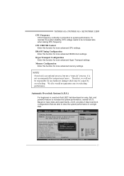
... lth Configuration > Power Config uration > USB Configur ation Options for CPU S elect Screen S elect Item EnterG o to malfunction. TA790GX A2+/TA790GX A2+ SE/TA790GX 128M BIOS Manual 2 Advanced Menu T he Advanced Menu allows you to Change Freq : uCode Patch Le vel : Secure Virtual Machine... Mode Cool N Quiet ACPI SRAT Tabl e [Ena bled] [Ena bled] [Ena bled] S elect Screen S elect Item +- Main Advan ced PCIPnP BIOS SETU P U TILITY Boot Chipset...
... lth Configuration > Power Config uration > USB Configur ation Options for CPU S elect Screen S elect Item EnterG o to malfunction. TA790GX A2+/TA790GX A2+ SE/TA790GX 128M BIOS Manual 2 Advanced Menu T he Advanced Menu allows you to Change Freq : uCode Patch Le vel : Secure Virtual Machine... Mode Cool N Quiet ACPI SRAT Tabl e [Ena bled] [Ena bled] [Ena bled] S elect Screen S elect Item +- Main Advan ced PCIPnP BIOS SETU P U TILITY Boot Chipset...

Bios Setup
Page 17
... f the CPU itselfuses when communicating with its own special components. Clear NV RAM T his section describes con figuring the PCI bus system. TA790GX A2+/TA790GX A2+ SE/TA790GX 128M BIOS Manual 3 PCIPnP Menu T his item allows you to NO, BIOS will initialize all the PnP cards. Clear NVRAM Plug & Play... that setting inappropriate values in below sections may cause system to malf unction. Main Advan ced BIOS SETU P U TILITY PCIPnP Boot Chipset T-Series Exit Advanced PCI/P nP Settings WARNING: Setti ng wrong values in items of the cards will only initialize the PnP cards ...
... f the CPU itselfuses when communicating with its own special components. Clear NV RAM T his section describes con figuring the PCI bus system. TA790GX A2+/TA790GX A2+ SE/TA790GX 128M BIOS Manual 3 PCIPnP Menu T his item allows you to NO, BIOS will initialize all the PnP cards. Clear NVRAM Plug & Play... that setting inappropriate values in below sections may cause system to malf unction. Main Advan ced BIOS SETU P U TILITY PCIPnP Boot Chipset T-Series Exit Advanced PCI/P nP Settings WARNING: Setti ng wrong values in items of the cards will only initialize the PnP cards ...

Bios Setup
Page 20
Main Advan ced BIOS SETU P U TILITY PCIPnP Boot Chipset T-Series Exit Boot Settings Configuration > Boot Device Priority > Hard Disk Dr ives > Removable Dr ives > CD/DVD Drive s Quick Boot [Ena bled] Full Screen LO ... priority sequence from the available devices. Master / Pri. Slave / Sec. Options: Floppy Disks / Zip100 / USB-FDD0 / USB-FDD1 / USB-ZIP0 / USB-ZIP1 / LS120 19 TA790GX A2+/TA790GX A2+ SE/TA790GX 128M BIOS Manual 4 Boot Menu T his menu allows you to Sub Screen F1 G eneral Help F10 S ave and Exit ESC E xit vxx .xx (C)Copyright 1985...
Main Advan ced BIOS SETU P U TILITY PCIPnP Boot Chipset T-Series Exit Boot Settings Configuration > Boot Device Priority > Hard Disk Dr ives > Removable Dr ives > CD/DVD Drive s Quick Boot [Ena bled] Full Screen LO ... priority sequence from the available devices. Master / Pri. Slave / Sec. Options: Floppy Disks / Zip100 / USB-FDD0 / USB-FDD1 / USB-ZIP0 / USB-ZIP1 / LS120 19 TA790GX A2+/TA790GX A2+ SE/TA790GX 128M BIOS Manual 4 Boot Menu T his menu allows you to Sub Screen F1 G eneral Help F10 S ave and Exit ESC E xit vxx .xx (C)Copyright 1985...

Bios Setup
Page 22
... Options for NB S elect Screen S elect Item EnterG o to configure the speci fic features of the chipset installed on your system. It also coordinates communications with the PCI bus. TA790GX A2+/TA790GX A2+ SE/TA790GX 128M BIOS Manual 5 Chipset Menu T his chipset manage bus speeds and access to Sub Screen F1 G eneral Help F10 S ave and Exit ESC...
... Options for NB S elect Screen S elect Item EnterG o to configure the speci fic features of the chipset installed on your system. It also coordinates communications with the PCI bus. TA790GX A2+/TA790GX A2+ SE/TA790GX 128M BIOS Manual 5 Chipset Menu T his chipset manage bus speeds and access to Sub Screen F1 G eneral Help F10 S ave and Exit ESC...

Bios Setup
Page 23
TA790GX A2+/TA790GX A2+ SE/TA790GX 128M BIOS Manual EC Configuration BIOS SETU P U TILITY Chipset SureBoot Featu re SureBoot Timeo ut Advanced Clock Calibration Value (All C ores) Value (Core 0) Value (Core 1) Value (Core 2) Value (Core 3) [Ena bled] [4 S econds] [Dis abled] [- 2 %] [- 2 %] [- 2 %] [- 2 %] [- 2 %] ...
TA790GX A2+/TA790GX A2+ SE/TA790GX 128M BIOS Manual EC Configuration BIOS SETU P U TILITY Chipset SureBoot Featu re SureBoot Timeo ut Advanced Clock Calibration Value (All C ores) Value (Core 0) Value (Core 1) Value (Core 2) Value (Core 3) [Ena bled] [4 S econds] [Dis abled] [- 2 %] [- 2 %] [- 2 %] [- 2 %] [- 2 %] ...
