
Setup Manual
Page 2
... (CPU 8 2.2 FAN Headers 10 2.3 Installing System Memory 11 2.4 Connectors and Slots 13 Chapter 3: Headers & Jumpers Setup 15 3.1 How to Setup Jumpers 15 3.2 Detail Settings 15 Chapter 4: RAID Functions 22 4.1 Operation System 22 4.2 Raid Arrays 22 4.3 How RAID Works 22 Chapter 5: OverClock Quick Guide 25 5.1 T-Power Introduction 25 5.2 T-Power BIOS Feature 26 5.3 T-Power Windows Feature 34 Chapter 6: Useful Help 43 6.1 Driver Installation Note 43 6.2 Award BIOS Beep Code 44 6.3 Extra Information 44 6.4 Troubleshooting 46 Appendencies: SPEC...
... (CPU 8 2.2 FAN Headers 10 2.3 Installing System Memory 11 2.4 Connectors and Slots 13 Chapter 3: Headers & Jumpers Setup 15 3.1 How to Setup Jumpers 15 3.2 Detail Settings 15 Chapter 4: RAID Functions 22 4.1 Operation System 22 4.2 Raid Arrays 22 4.3 How RAID Works 22 Chapter 5: OverClock Quick Guide 25 5.1 T-Power Introduction 25 5.2 T-Power BIOS Feature 26 5.3 T-Power Windows Feature 34 Chapter 6: Useful Help 43 6.1 Driver Installation Note 43 6.2 Award BIOS Beep Code 44 6.3 Extra Information 44 6.4 Troubleshooting 46 Appendencies: SPEC...
Setup Manual
Page 3
... power outlet before operation. „ Before you for ATX Case X 1 User's Manual X 1 Fully Setup Driver CD X 1 FDD Cable X 1 (optional) USB 2.0 Cable X1 (optional) S/PDIF out Cable X 1 (optional) 3 Before you start installing the motherboard, please make sure you follow the instructions below: „ Prepare a dry and stable working environment with sufficient lighting. „ Always disconnect the computer from dangerous area, such as heat source, humid air and water. 1.2 PACKAGE CHECKLIST HDD Cable X 1 Serial ATA Cable...
... power outlet before operation. „ Before you for ATX Case X 1 User's Manual X 1 Fully Setup Driver CD X 1 FDD Cable X 1 (optional) USB 2.0 Cable X1 (optional) S/PDIF out Cable X 1 (optional) 3 Before you start installing the motherboard, please make sure you follow the instructions below: „ Prepare a dry and stable working environment with sufficient lighting. „ Always disconnect the computer from dangerous area, such as heat source, humid air and water. 1.2 PACKAGE CHECKLIST HDD Cable X 1 Serial ATA Cable...
Setup Manual
Page 4
... x 1 slot x2 Supports PCI expansion cards x1 Supports PCI express x16 expansion cards x1 Supports PCI express x1 expansion cards On Board Floppy connector Connector Printer Port connector x1 Each connector supports 2 Floppy drives x1 Each connector supports 1 Printer port 4 SATA Version 2.0 specification compliant. Fan Speed Controller Low Pin Count Interface ITE's "Smart Guardian" function Main Memory DDR2 DIMM Slots x 4 Max Memory Capacity 4GB Graphics Integrated in AMD 690G (for HDMI Audio) Integrated in AMD 690G Chipset Each DIMM supports 256/512MB & 1GB DDR2 Dual Channel Mode...
... x 1 slot x2 Supports PCI expansion cards x1 Supports PCI express x16 expansion cards x1 Supports PCI express x1 expansion cards On Board Floppy connector Connector Printer Port connector x1 Each connector supports 2 Floppy drives x1 Each connector supports 1 Printer port 4 SATA Version 2.0 specification compliant. Fan Speed Controller Low Pin Count Interface ITE's "Smart Guardian" function Main Memory DDR2 DIMM Slots x 4 Max Memory Capacity 4GB Graphics Integrated in AMD 690G (for HDMI Audio) Integrated in AMD 690G Chipset Each DIMM supports 256/512MB & 1GB DDR2 Dual Channel Mode...

Setup Manual
Page 5
IDE Connector SATA Connector Front Panel Connector Front Audio Connector CD-in Connector S/PDIF out connector S/PDIF in connector (Optional) CPU Fan header System Fan header CMOS clear header USB connector Serial port Connector Power Connector (24pin) Power Connector (4pin) PS/2 Keyboard PS/2 Mouse S-Video port Back Panel I/O HDMI port VGA port DVI-D port LAN port USB Port Audio Jack Board Size 244 mm(W) x 244 mm(L) Special Features RAID 0 / 1 / 1+0 support OS Support Windows XP / VISTA TA690G AM2 SPEC x1 Each connector supports 2 IDE device x4 Each connector supports...
IDE Connector SATA Connector Front Panel Connector Front Audio Connector CD-in Connector S/PDIF out connector S/PDIF in connector (Optional) CPU Fan header System Fan header CMOS clear header USB connector Serial port Connector Power Connector (24pin) Power Connector (4pin) PS/2 Keyboard PS/2 Mouse S-Video port Back Panel I/O HDMI port VGA port DVI-D port LAN port USB Port Audio Jack Board Size 244 mm(W) x 244 mm(L) Special Features RAID 0 / 1 / 1+0 support OS Support Windows XP / VISTA TA690G AM2 SPEC x1 Each connector supports 2 IDE device x4 Each connector supports...

Setup Manual
Page 6
... interfaces cannot work simultaneously either. Motherboard Manual 1.4 REAR PANEL CONNECTORS X PS/2 Mouse Port Y PS/2 Keyboard Port Z S-Video TV-Out Port Transmit analog video signals to TV or any compatible digital audio and/or video monitor, such as flat panel LCDs or digital projectors. The AMD 690G chipset uses the same channel to control S-Video and D-Sub for transmitting analog video signals, so these ports cannot transmit video signal to control HDMI and DVI-D, so these ports cannot work at...
... interfaces cannot work simultaneously either. Motherboard Manual 1.4 REAR PANEL CONNECTORS X PS/2 Mouse Port Y PS/2 Keyboard Port Z S-Video TV-Out Port Transmit analog video signals to TV or any compatible digital audio and/or video monitor, such as flat panel LCDs or digital projectors. The AMD 690G chipset uses the same channel to control S-Video and D-Sub for transmitting analog video signals, so these ports cannot transmit video signal to control HDMI and DVI-D, so these ports cannot work at...

Setup Manual
Page 7
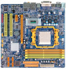
DVI-D VGA 1.5 MOTHERBOARD LAYOUT JKBMS1 JATXPWR2 JCFAN1 TA690G AM2 JATXPWR1 JTVOUT1 JHDMI DIMMA1 DIMMB1 DIMMA2 DIMMB2 Socket A M2 JUSB1 JUSBLAN1 JNFAN1 AMD 690G IDE1 FDD1 AUDIO1 LAN JAUDIOF1 PEX16_1 Codec PEX1_1 JSPDIF_OUT1 JSPDIF_IN1 JCDIN1 PCI1 BAT1 JCMOS1 AMD SB600 BIOS SATA2 SATA1 Super I/O JPRNT1 PCI2 JCOM1 JUSB2 JUSB3 LED_D1 LED_D2 SATA4 SATA3 JUSB4 JSFAN2 JPANEL1 PWRSW1 JSFAN1 RSTSW1 Note: ■ represents the 1st pin. 7
DVI-D VGA 1.5 MOTHERBOARD LAYOUT JKBMS1 JATXPWR2 JCFAN1 TA690G AM2 JATXPWR1 JTVOUT1 JHDMI DIMMA1 DIMMB1 DIMMA2 DIMMB2 Socket A M2 JUSB1 JUSBLAN1 JNFAN1 AMD 690G IDE1 FDD1 AUDIO1 LAN JAUDIOF1 PEX16_1 Codec PEX1_1 JSPDIF_OUT1 JSPDIF_IN1 JCDIN1 PCI1 BAT1 JCMOS1 AMD SB600 BIOS SATA2 SATA1 Super I/O JPRNT1 PCI2 JCOM1 JUSB2 JUSB3 LED_D1 LED_D2 SATA4 SATA3 JUSB4 JSFAN2 JPANEL1 PWRSW1 JSFAN1 RSTSW1 Note: ■ represents the 1st pin. 7

Setup Manual
Page 12
Dual Channel Status DIMMA1 DIMMB1 DIMMA2 DIMMB2 Enabled O O X X Enabled X X O O Enabled O O O O (O means memory installed, X means memory not installed.) The DRAM bus width of the memory module must meet the following requirements: Install memory module of the motherboard, the memory module must be the same (x8 or x16) 12 Dual Channel Memory installation To trigger the Dual Channel function of the same density in pairs, shown in the following table. C. Motherboard Manual B. Memory Capacity DIMM Socket Location DDR2 Module DIMMA1...
Dual Channel Status DIMMA1 DIMMB1 DIMMA2 DIMMB2 Enabled O O X X Enabled X X O O Enabled O O O O (O means memory installed, X means memory not installed.) The DRAM bus width of the memory module must meet the following requirements: Install memory module of the motherboard, the memory module must be the same (x8 or x16) 12 Dual Channel Memory installation To trigger the Dual Channel function of the same density in pairs, shown in the following table. C. Motherboard Manual B. Memory Capacity DIMM Socket Location DDR2 Module DIMMA1...
Setup Manual
Page 13
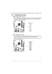
TA690G AM2 2.4 CONNECTORS AND SLOTS FDD1: Floppy Disk Connector The motherboard provides a standard floppy disk connector that provides PIO Mode 0~4, Bus Master, and Ultra DMA 33/66/100/133 functionality. The IDE connector can connect a master and a slave drive, so you can connect up to two hard disk drives. 40 39 21 13 This connector supports the provided floppy drive ribbon cables. 34 33 2 1 IDE1: Hard Disk Connector The motherboard has a 32-bit Enhanced PCI IDE Controller that supports 360K, 720K, 1.2M, 1.44M and 2.88M floppy disk types.
TA690G AM2 2.4 CONNECTORS AND SLOTS FDD1: Floppy Disk Connector The motherboard provides a standard floppy disk connector that provides PIO Mode 0~4, Bus Master, and Ultra DMA 33/66/100/133 functionality. The IDE connector can connect a master and a slave drive, so you can connect up to two hard disk drives. 40 39 21 13 This connector supports the provided floppy drive ribbon cables. 34 33 2 1 IDE1: Hard Disk Connector The motherboard has a 32-bit Enhanced PCI IDE Controller that supports 360K, 720K, 1.2M, 1.44M and 2.88M floppy disk types.
Setup Manual
Page 15
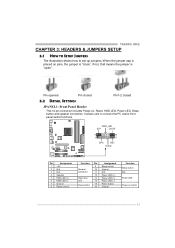
TA690G AM2 CHAPTER 3: HEADERS & JUMPERS SETUP 3.1 HOW TO SETUP JUMPERS The illustration shows how to connect the PC case's front panel switch functions. It allows user to set up jumpers. PWR_LED SLP On/Off ++ - 9 16 1 +- 8 SPK RST HLED Pin Assignment 1 +5V 2 N/A 3 N/A 4 Speaker 5 HDD LED (+) 6 HDD LED (-) 7 Ground 8 Reset control Function Pin Assignment 9 Sleep control Speaker Connector 10 Ground 11 N/A 12 Power LED (+) Hard drive LED 13 Power LED (+) 14 Power LED (-) Reset button 15 Power button 16 Ground Function Sleep button N/A Power LED Power-on ,...
TA690G AM2 CHAPTER 3: HEADERS & JUMPERS SETUP 3.1 HOW TO SETUP JUMPERS The illustration shows how to connect the PC case's front panel switch functions. It allows user to set up jumpers. PWR_LED SLP On/Off ++ - 9 16 1 +- 8 SPK RST HLED Pin Assignment 1 +5V 2 N/A 3 N/A 4 Speaker 5 HDD LED (+) 6 HDD LED (-) 7 Ground 8 Reset control Function Pin Assignment 9 Sleep control Speaker Connector 10 Ground 11 N/A 12 Power LED (+) Hard drive LED 13 Power LED (+) 14 Power LED (-) Reset button 15 Power button 16 Ground Function Sleep button N/A Power LED Power-on ,...
Setup Manual
Page 17
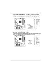
... on the PC front panel, and also can be connected with the PC front panel. JUSB2 JUSB3 JUSB4 2 10 1 9 Pin Assignment 1 +5V (fused) 2 +5V (fused) 3 USB4 USB5 USB+ 6 USB+ 7 Ground 8 Ground 9 Key 10 NC JAUDIOF1: Front Panel Audio Header This header allows user to connect additional USB cable on back panel audio connectors. TA690G AM2 JUSB2/JUSB3/JUSB4: Headers for USB 2.0 Ports at Front Panel This header allows user to connect the front audio output cable with internal USB devices, like USB card reader.
... on the PC front panel, and also can be connected with the PC front panel. JUSB2 JUSB3 JUSB4 2 10 1 9 Pin Assignment 1 +5V (fused) 2 +5V (fused) 3 USB4 USB5 USB+ 6 USB+ 7 Ground 8 Ground 9 Key 10 NC JAUDIOF1: Front Panel Audio Header This header allows user to connect additional USB cable on back panel audio connectors. TA690G AM2 JUSB2/JUSB3/JUSB4: Headers for USB 2.0 Ports at Front Panel This header allows user to connect the front audio output cable with internal USB devices, like USB card reader.

Setup Manual
Page 18
... five seconds. 4. Motherboard Manual JCDIN1: CD-ROM Audio-in Connector This connector allows user to connect the audio source from the variaty devices, like CD-ROM, DVD-ROM, PCI sound card, PCI TV turner card etc.. 4 1 Pin Assignment 1 Left Channel Input 2 Ground 3 Ground 4 Right Channel Input JCMOS1: Clear CMOS Header By placing the jumper on the AC. 6. Set the jumper to "Pin 2-3 close ". 5. Set the jumper to "Pin 1-2 close ". 3. Power on pin2-3, it allows user to restore the BIOS safe setting and the CMOS data, please carefully...
... five seconds. 4. Motherboard Manual JCDIN1: CD-ROM Audio-in Connector This connector allows user to connect the audio source from the variaty devices, like CD-ROM, DVD-ROM, PCI sound card, PCI TV turner card etc.. 4 1 Pin Assignment 1 Left Channel Input 2 Ground 3 Ground 4 Right Channel Input JCMOS1: Clear CMOS Header By placing the jumper on the AC. 6. Set the jumper to "Pin 2-3 close ". 5. Set the jumper to "Pin 1-2 close ". 3. Power on pin2-3, it allows user to restore the BIOS safe setting and the CMOS data, please carefully...
Setup Manual
Page 19
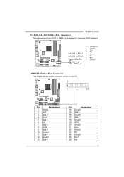
... SATA4 SATA3 5 RX- 14 7 6 RX+ 7 Ground JPRNT1: Printer Port Connector This header allows you to SATA Controller with 4 channels SATA interface. TA690G AM2 SATA1~SATA4: Serial ATA Connectors The motherboard has a PCI to connector printer on the PC. 2 1 25 Pin Assignment 1 -Strobe 2 -ALF 3 Data 0 4 -Error 5 Data 1 6 -Init 7 Data 2 8 -Scltin 9 Data 3 10 Ground 11 Data 4 12 Ground 13 Data 5 Pin Assignment 14 Ground 15 Data 6 16 Ground 17...
... SATA4 SATA3 5 RX- 14 7 6 RX+ 7 Ground JPRNT1: Printer Port Connector This header allows you to SATA Controller with 4 channels SATA interface. TA690G AM2 SATA1~SATA4: Serial ATA Connectors The motherboard has a PCI to connector printer on the PC. 2 1 25 Pin Assignment 1 -Strobe 2 -ALF 3 Data 0 4 -Error 5 Data 1 6 -Init 7 Data 2 8 -Scltin 9 Data 3 10 Ground 11 Data 4 12 Ground 13 Data 5 Pin Assignment 14 Ground 15 Data 6 16 Ground 17...

Setup Manual
Page 20
...out Connector (Optional) This connector allows user to send 9 Ring indicator 10 Key 20 Pin Assignment 1 +5V 2 SPDIF_IN 3 Ground 3 1 JCOM1: Serial port Connector The motherboard has a Serial Port Connector for connecting RS-232 Port. Pin Assignment 2 10 1 Carrier detect 2 Received data 3 Transmitted data 1 9 4 Data terminal ready 5 Signal ground 6 Data set ready 7 Request to send 8 Clear to connect the PCI bracket SPDIF input header. Motherboard Manual JSPDIF_OUT1: Digital Audio-out Connector This connector allows user to connect the PCI bracket SPDIF output header.
...out Connector (Optional) This connector allows user to send 9 Ring indicator 10 Key 20 Pin Assignment 1 +5V 2 SPDIF_IN 3 Ground 3 1 JCOM1: Serial port Connector The motherboard has a Serial Port Connector for connecting RS-232 Port. Pin Assignment 2 10 1 Carrier detect 2 Received data 3 Transmitted data 1 9 4 Data terminal ready 5 Signal ground 6 Data set ready 7 Request to send 8 Clear to connect the PCI bracket SPDIF input header. Motherboard Manual JSPDIF_OUT1: Digital Audio-out Connector This connector allows user to connect the PCI bracket SPDIF output header.
Setup Manual
Page 25
... Biostar T-Power is a whole new utility that is able to present the best system state according to raise system performance. T-Power BIOS Features: Overclocking Navigator Engine (O.N.E.) CMOS Reloading Program (C.R.P.) Memory Integration Test (M.I.T., under Overclock Navigator Engine) Integrated Flash Program (I.F.P.) Smart Fan Function (under BIOS or Windows interface, T-Power is designed for overclock users. No matter whether under PC Health Status) Self Recovery System (S.R.S) T-Power Windows Feature: Hardware Monitor Overclock Engine Smart Fan Function Life Update...
... Biostar T-Power is a whole new utility that is able to present the best system state according to raise system performance. T-Power BIOS Features: Overclocking Navigator Engine (O.N.E.) CMOS Reloading Program (C.R.P.) Memory Integration Test (M.I.T., under Overclock Navigator Engine) Integrated Flash Program (I.F.P.) Smart Fan Function (under BIOS or Windows interface, T-Power is designed for overclock users. No matter whether under PC Health Status) Self Recovery System (S.R.S) T-Power Windows Feature: Hardware Monitor Overclock Engine Smart Fan Function Life Update...
Setup Manual
Page 27
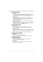
... by different CPU type. With an x1 (200MHz) interval. PCI-Express Overclock Setting: PCIE Clock: It helps to downgrade the CPU ratio when overclocking. Hammer CPU Multiplier: The MOS allows users to increase VGA card performance. Memory Overclock Setting: Memory Voltage: This function will increase chipset stability when overclocking. Choices: DDR2 400, DDR2 533, DDR2 667, DDR2 800 (MHz). Chipset Overclock Setting: NB/SB Voltage Regulator: This function will increase memory stability when overclocking. Memclock Frequency: To get...
... by different CPU type. With an x1 (200MHz) interval. PCI-Express Overclock Setting: PCIE Clock: It helps to downgrade the CPU ratio when overclocking. Hammer CPU Multiplier: The MOS allows users to increase VGA card performance. Memory Overclock Setting: Memory Voltage: This function will increase chipset stability when overclocking. Choices: DDR2 400, DDR2 533, DDR2 667, DDR2 800 (MHz). Chipset Overclock Setting: NB/SB Voltage Regulator: This function will increase memory stability when overclocking. Memclock Frequency: To get...

Setup Manual
Page 30
... is done, change the setting back from CMOS setup and reboot the system to activate this test for 5 minutes (minimum) to ensure the memory stability. the condition parameter should be changed to "Enable" to proceed this test. ↓ Step 2: Save and Exit from "Enable" to "Disable" to test memory compatibilities, and no extra devices or software are needed. Step 1: The default setting under "Overclocking Navigator Engine...
... is done, change the setting back from CMOS setup and reboot the system to activate this test for 5 minutes (minimum) to ensure the memory stability. the condition parameter should be changed to "Enable" to proceed this test. ↓ Step 2: Save and Exit from "Enable" to "Disable" to test memory compatibilities, and no extra devices or software are needed. Step 1: The default setting under "Overclocking Navigator Engine...

Setup Manual
Page 31
... floppy disk and reboot the system to inappropriate overclock actions. Step 3: Select the item "Integrated Flash Program" to start BIOS file loading, and BIOS updating will be seen under T-Power BIOS setup; Step 4: Press "Enter" key to get into a floppy disk. Self Recovery System (S.R.S.): This function can't be re-configured. Integrated Flash Program (I.F.P.): IFP is a safe and quick way to download the latest BIOS file. Step 1: Go to Biostar website (http://www.biostar.com.tw) to upgrade BIOS...
... floppy disk and reboot the system to inappropriate overclock actions. Step 3: Select the item "Integrated Flash Program" to start BIOS file loading, and BIOS updating will be seen under T-Power BIOS setup; Step 4: Press "Enter" key to get into a floppy disk. Self Recovery System (S.R.S.): This function can't be re-configured. Integrated Flash Program (I.F.P.): IFP is a safe and quick way to download the latest BIOS file. Step 1: Go to Biostar website (http://www.biostar.com.tw) to upgrade BIOS...

Setup Manual
Page 39
PCI Overclocking Setting: TA690G AM2 This diagram shows present PCI working status and helps to monitor PCI peripherals working status. This item cannot be adjusted. 39
PCI Overclocking Setting: TA690G AM2 This diagram shows present PCI working status and helps to monitor PCI peripherals working status. This item cannot be adjusted. 39

Setup Manual
Page 44
... recovered and will update BIOS automatically and restart. 9. BIOS Update After you fail to update BIOS or BIOS is shown after boot-up the system, it means the BIOS contents are corrupted. In this Case, please follow the procedure below to restore the BIOS: 1. Copy "AWDFLASH.exe" and respectively BIOS into floppy drive and press Enter. 6. System will work properly. 44 Motherboard Manual 6.2 AWARD BIOS BEEP CODE Beep Sound Meaning One long beep followed by virus...
... recovered and will update BIOS automatically and restart. 9. BIOS Update After you fail to update BIOS or BIOS is shown after boot-up the system, it means the BIOS contents are corrupted. In this Case, please follow the procedure below to restore the BIOS: 1. Copy "AWDFLASH.exe" and respectively BIOS into floppy drive and press Enter. 6. System will work properly. 44 Motherboard Manual 6.2 AWARD BIOS BEEP CODE Beep Sound Meaning One long beep followed by virus...

Setup Manual
Page 46
... the hard drive is in the standard CMOS setup. Screen message says "Invalid Configuration" or "CMOS Failure." Call the drive manufacturers for compatibility with other drives. 46 on both ends are on . is spinning. Make sure correct information is extremely important. Run SETUP program and select correct drive types. Set master/slave jumpers correctly. 2. Using even pressure on . 3. Review system's equipment. Motherboard Manual 6.4 TROUBLESHOOTING Probable Solution 1. inside power supply does not turn on , power indicator lights...
... the hard drive is in the standard CMOS setup. Screen message says "Invalid Configuration" or "CMOS Failure." Call the drive manufacturers for compatibility with other drives. 46 on both ends are on . is spinning. Make sure correct information is extremely important. Run SETUP program and select correct drive types. Set master/slave jumpers correctly. 2. Using even pressure on . 3. Review system's equipment. Motherboard Manual 6.4 TROUBLESHOOTING Probable Solution 1. inside power supply does not turn on , power indicator lights...


