
M6VCG user's manual
Page 14
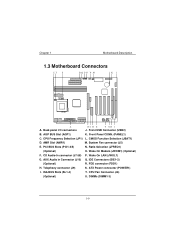
... L. PCI BUS Slots (PCI1-4/5) N. Wake On Modem (JWOM1) (Optional) F. IDE Connectors (IDE1-2) (Optional) R. ISA BUS Slots (SL1-4) T. AGP BUS Slot (AGP1) K. AMR Slot (AMR1) M. Ratio Selection (JFREQ1) (Optional) O. AUX Audio in Connector (J10) Q. Chapter 1 Motherboard Description 1.3 Motherboard Connectors A. CMOS Function Selection (JBAT1) D. DIMMs (DIMM1-3) Front Panel CONN. (PANEL1) C. System Fan connector (J5) E. Wake On LAN (JWOL1) G. ATX Power connector (POWER1) I /O connectors J. Back panel I . FDD connector (FDD1) H. CPU Fan Connector (J6...
... L. PCI BUS Slots (PCI1-4/5) N. Wake On Modem (JWOM1) (Optional) F. IDE Connectors (IDE1-2) (Optional) R. ISA BUS Slots (SL1-4) T. AGP BUS Slot (AGP1) K. AMR Slot (AMR1) M. Ratio Selection (JFREQ1) (Optional) O. AUX Audio in Connector (J10) Q. Chapter 1 Motherboard Description 1.3 Motherboard Connectors A. CMOS Function Selection (JBAT1) D. DIMMs (DIMM1-3) Front Panel CONN. (PANEL1) C. System Fan connector (J5) E. Wake On LAN (JWOL1) G. ATX Power connector (POWER1) I /O connectors J. Back panel I . FDD connector (FDD1) H. CPU Fan Connector (J6...
M6VCG user's manual
Page 15
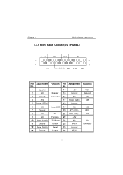
Chapter 1 Motherboard Description 1.3.1 Front Panel Connectors : PANEL1 NC Pin Assignment Function No. 1 Speaker 2 NC Speaker 3 Ground Connector 4 +5V 5 Power LED(+) 6 NC Power LED 7 Ground 8 NC No 9 NC Function 10 Power Switch ATX Power 11 Ground Button 12 Reset Switch Reset 13 Ground Button Pin Assignment No. 14 +5V 15 Ground 16 NC 17 Sleep Switch 18 Ground 19 NC 20 HDD LED(-) 21 HDD LED(+) 22 +5V 23 NC 24 IRRX 25 Ground 26 IRTX Function VCC Ground NC SMI NC HDD LED IrDA Connector
Chapter 1 Motherboard Description 1.3.1 Front Panel Connectors : PANEL1 NC Pin Assignment Function No. 1 Speaker 2 NC Speaker 3 Ground Connector 4 +5V 5 Power LED(+) 6 NC Power LED 7 Ground 8 NC No 9 NC Function 10 Power Switch ATX Power 11 Ground Button 12 Reset Switch Reset 13 Ground Button Pin Assignment No. 14 +5V 15 Ground 16 NC 17 Sleep Switch 18 Ground 19 NC 20 HDD LED(-) 21 HDD LED(+) 22 +5V 23 NC 24 IRRX 25 Ground 26 IRTX Function VCC Ground NC SMI NC HDD LED IrDA Connector
M6VCG user's manual
Page 19
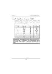
Chapter 1 Motherboard Description 1.3.2 ATX 20-pin Power Connector : POWER1 PIN VOLTAGE PIN VOLTAGE 1 3.3 V 11 3.3 V 2 3.3 V 12 -12 V 3 GND 13 GND 4 5 V 14 PS_ON 5 GND 15 GND 6 5 V 16 GND 7 GND 17 GND 8 PW_OK 18 -5 V (Optional) 9 5V_SB 19 5 V 10 12 V 20 5 V Warning: Since the motherboard has the instant power on function, make sure that all components are installed properly before inserting the power connector to ensure that no damage will be done.
Chapter 1 Motherboard Description 1.3.2 ATX 20-pin Power Connector : POWER1 PIN VOLTAGE PIN VOLTAGE 1 3.3 V 11 3.3 V 2 3.3 V 12 -12 V 3 GND 13 GND 4 5 V 14 PS_ON 5 GND 15 GND 6 5 V 16 GND 7 GND 17 GND 8 PW_OK 18 -5 V (Optional) 9 5V_SB 19 5 V 10 12 V 20 5 V Warning: Since the motherboard has the instant power on function, make sure that all components are installed properly before inserting the power connector to ensure that no damage will be done.
M6VCG user's manual
Page 33
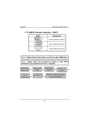
Note : Please follow the procedure as below to clear BIOS Password if your desired password or Clear CMOS Data Chapter 1 Motherboard Description 1.7.5 CMOS Function Selection : JBAT1 JBAT1 1 3 1-2 Closed 1 3 2-3 Closed 1 3 Open Assignment Normal Operation (default) Clear CMOS Data (*Note) Onboard Battery Disabled Note : Please follow the procedure as below to clear CMOS Data. Remove AC Power Line Plug AC Power Line JBAT1 (2-3) closed AC Power On Wait three seconds JBAT1 (1-2) closed Reset your password is lost or forgotten.
Note : Please follow the procedure as below to clear BIOS Password if your desired password or Clear CMOS Data Chapter 1 Motherboard Description 1.7.5 CMOS Function Selection : JBAT1 JBAT1 1 3 1-2 Closed 1 3 2-3 Closed 1 3 Open Assignment Normal Operation (default) Clear CMOS Data (*Note) Onboard Battery Disabled Note : Please follow the procedure as below to clear CMOS Data. Remove AC Power Line Plug AC Power Line JBAT1 (2-3) closed AC Power On Wait three seconds JBAT1 (1-2) closed Reset your password is lost or forgotten.
M6VCG user's manual
Page 41
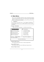
WARNING !! " Standard CMOS Features Advanced BIOS Features Advanced Chipset Features Integrated Peripherals Power Management Setup PnP/PCI Configurations PC Health Status Load Optimized Defaults Set Supervisor Password Set User Password Save & Exit Setup Exit Without Saving Esc : Quit F9: Menu in BIOS F10 : Save & Exit Setup Time, Date, Hard Disk Type... : Select Item Chapter 2 2.1 Main Menu BIOS Setup !!
WARNING !! " Standard CMOS Features Advanced BIOS Features Advanced Chipset Features Integrated Peripherals Power Management Setup PnP/PCI Configurations PC Health Status Load Optimized Defaults Set Supervisor Password Set User Password Save & Exit Setup Exit Without Saving Esc : Quit F9: Menu in BIOS F10 : Save & Exit Setup Time, Date, Hard Disk Type... : Select Item Chapter 2 2.1 Main Menu BIOS Setup !!
M6VCG user's manual
Page 44
... Select the type of floppy disk drive installed in your system. 720K, 3.5 in 1.44M, 3.5 in 2.88M, 3.5 in its sub Press to enter the menu. sub menu of detailed options. CGA 80 MONO IDE Primary Master Options are in its sub Press to enter the menu. IDE Secondary Master Options are in Video EGA/VGA CGA 40 Select the default video device. Chapter 2 BIOS Setup Item Options Description Date Moth DD YYYY Set the system...
... Select the type of floppy disk drive installed in your system. 720K, 3.5 in 1.44M, 3.5 in 2.88M, 3.5 in its sub Press to enter the menu. sub menu of detailed options. CGA 80 MONO IDE Primary Master Options are in its sub Press to enter the menu. IDE Secondary Master Options are in Video EGA/VGA CGA 40 Select the default video device. Chapter 2 BIOS Setup Item Options Description Date Moth DD YYYY Set the system...
M6VCG user's manual
Page 46
... First Boot Device Second Boot Device Third Boot Device Boot Other Dvice Swap Floopy Drive Boot Up Numlock Status Gate A20 Option Security Option OS Select For DRAM > 64 MB Report No FDD For WIN 98 Video BIOS Shadow C8000-CBFFF Shadow CC000-CFFFF Shadow D0000-D3FFF Shadow D4000-D7FFF Shadow D8000-DBFFF Shadow DC000-DFFFF Shadow Disabled Enabled Enabled Enabled Disabled Enabled Floppy HDD-0 CDROM Enabled Disabled On Fast Setup Non-OS2 No Enabled Disabled Disabled Disabled Disabled Disabled Disabled Item Help Menu...
... First Boot Device Second Boot Device Third Boot Device Boot Other Dvice Swap Floopy Drive Boot Up Numlock Status Gate A20 Option Security Option OS Select For DRAM > 64 MB Report No FDD For WIN 98 Video BIOS Shadow C8000-CBFFF Shadow CC000-CFFFF Shadow D0000-D3FFF Shadow D4000-D7FFF Shadow D8000-DBFFF Shadow DC000-DFFFF Shadow Disabled Enabled Enabled Enabled Disabled Enabled Floppy HDD-0 CDROM Enabled Disabled On Fast Setup Non-OS2 No Enabled Disabled Disabled Disabled Disabled Disabled Disabled Item Help Menu...
M6VCG user's manual
Page 53
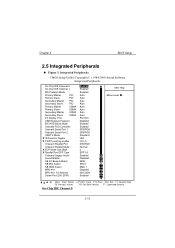
... Peripherals " BIOS Setup On-Chip IDE Channel 0 On-Chip IDE Channel 1 IDE Prefetch Mode Primary Master PIO Primary Slave PIO Secondary Master PIO Secondary Slave PIO Primary Master UDMA Primary Slave UDMA Secondary Master UDMA Secondary Slave UDMA Init Display First USB Keyboard Support IDE HDD Block Mode Onboard FDD Controller Onboard Serial Port 1 Onboard Serial Port 2 UART 2 Mode X IR Function Duplex X TX,RX inverting enable Onboard Parallel Port Onboard Parallel Mode X ECP Mode Use DMA X Parallel Port EPP Type Onboard Legacy Audio Sound Blaster SB...
... Peripherals " BIOS Setup On-Chip IDE Channel 0 On-Chip IDE Channel 1 IDE Prefetch Mode Primary Master PIO Primary Slave PIO Secondary Master PIO Secondary Slave PIO Primary Master UDMA Primary Slave UDMA Secondary Master UDMA Secondary Slave UDMA Init Display First USB Keyboard Support IDE HDD Block Mode Onboard FDD Controller Onboard Serial Port 1 Onboard Serial Port 2 UART 2 Mode X IR Function Duplex X TX,RX inverting enable Onboard Parallel Port Onboard Parallel Mode X ECP Mode Use DMA X Parallel Port EPP Type Onboard Legacy Audio Sound Blaster SB...
M6VCG user's manual
Page 58
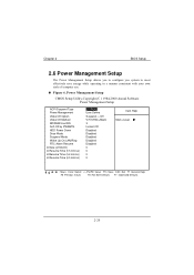
... 2 BIOS Setup 2.6 Power Management Setup " ACPI Suspend Type Power Management Video Off Option Video Off Method MODEM Use IRQ Soft-Off by PWRBTN HDD Power Down Doze Mode Suspend Mode Wake Up On LAN/Ring RTC Alarm Resume X Date (of Month) X Resume Time (hh:mm:ss) X Resume Time (hh:mm:ss) X Resume Time (hh:mm:ss) S1 (POS) User Define Suspend - Off V/H SYNC+Blank 3 Instant-Off Disabled Disabled Disabled Disabled Disabled 0 0 0 0 Item Help Menu...
... 2 BIOS Setup 2.6 Power Management Setup " ACPI Suspend Type Power Management Video Off Option Video Off Method MODEM Use IRQ Soft-Off by PWRBTN HDD Power Down Doze Mode Suspend Mode Wake Up On LAN/Ring RTC Alarm Resume X Date (of Month) X Resume Time (hh:mm:ss) X Resume Time (hh:mm:ss) X Resume Time (hh:mm:ss) S1 (POS) User Define Suspend - Off V/H SYNC+Blank 3 Instant-Off Disabled Disabled Disabled Disabled Disabled 0 0 0 0 Item Help Menu...
M6VCG user's manual
Page 62
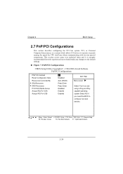
Chapter 2 2.7 PnP/PCI Configurations BIOS Setup " PNP OS Installed Reset Configuration Data Resources Controlled By X IRQ Resources X DMA Resources PCI/VGA Palette Snoop Assign IRQ For VGA Assign IRQ For USB NO Disabled Auto (ESCD) Press Enter Press Enter Disabled Enabled Enabled Item Help Menu Level Select Yes if you are using a Plug and Play capable operating system Select NO if you need the BIOS to configure non-boot devices : Move Enter :Select +/-/PU/PD :Value F10 :Save ESC :Exit F1 :General Help F5 :Previous Values F6 :Fail-Safe Defaults F7 : Optimized Defaults
Chapter 2 2.7 PnP/PCI Configurations BIOS Setup " PNP OS Installed Reset Configuration Data Resources Controlled By X IRQ Resources X DMA Resources PCI/VGA Palette Snoop Assign IRQ For VGA Assign IRQ For USB NO Disabled Auto (ESCD) Press Enter Press Enter Disabled Enabled Enabled Item Help Menu Level Select Yes if you are using a Plug and Play capable operating system Select NO if you need the BIOS to configure non-boot devices : Move Enter :Select +/-/PU/PD :Value F10 :Save ESC :Exit F1 :General Help F5 :Previous Values F6 :Fail-Safe Defaults F7 : Optimized Defaults

M6VCG user's manual
Page 67
Chapter 2 2.9 Load Optimized Defaults BIOS Setup " Standard CMOS Features PC Health Status Advanced BIOS Features Load Optimized Defaults Advanced Chipset Features Set Supervisor Password Integrated Peripherals Set User Password Power Management SeLtoupad Optimized DSeeftaUusltesr P(Ya/sNsw) o?rdN PnP/PCI Configurations Save & Exit Setup Exit Without Saving Esc : Quit F9: Menu in BIOS F10 : Save & Exit Setup Load Optimized Defaults : Select Item
Chapter 2 2.9 Load Optimized Defaults BIOS Setup " Standard CMOS Features PC Health Status Advanced BIOS Features Load Optimized Defaults Advanced Chipset Features Set Supervisor Password Integrated Peripherals Set User Password Power Management SeLtoupad Optimized DSeeftaUusltesr P(Ya/sNsw) o?rdN PnP/PCI Configurations Save & Exit Setup Exit Without Saving Esc : Quit F9: Menu in BIOS F10 : Save & Exit Setup Load Optimized Defaults : Select Item
M6VCG user's manual
Page 68
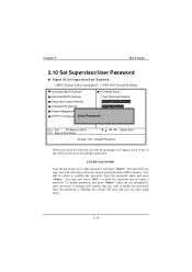
Chapter 2 BIOS Setup 2.10 Set Supervisor/User Password " Standard CMOS Features PC Health Status Advanced BIOS Features Load Optimized Defaults Advanced Chipset Features Set Supervisor Password Integrated Peripherals Set User Password Power Management Setup Save & Exit Setup PnP/PCI ConfigurationsEnter Password :Exit Without Saving Esc : Quit F9: Menu in BIOS F10 : Save & Exit Setup : Select Item Change / Set / Disable Password
Chapter 2 BIOS Setup 2.10 Set Supervisor/User Password " Standard CMOS Features PC Health Status Advanced BIOS Features Load Optimized Defaults Advanced Chipset Features Set Supervisor Password Integrated Peripherals Set User Password Power Management Setup Save & Exit Setup PnP/PCI ConfigurationsEnter Password :Exit Without Saving Esc : Quit F9: Menu in BIOS F10 : Save & Exit Setup : Select Item Change / Set / Disable Password
M6VCG user's manual
Page 72
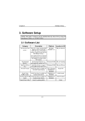
Software Setup Software Setup 3.1 Software List Category Description Platform Location in CD VIA Service Pack (4 In1) * VIA 4 IN 1 driver includes(VIA Registry (ACPI) Driver/VIA AGP VxD driver /VIA ATAPI Vendor Support Driver/VIA PCI IRQ Miniport Driver ) Windows 95/98/NT 4.0 \Mb_drv\Service four system drivers to support Windows 95/98 \Mb_drv\XStore Pro * Ultra DMA mode Hard Drive. Chapter 3 3. VIA AC97 Audio* Install the driver to enable the DOS, Windows VIA AC97 Audio Device 95/98/NT4.0/ WIN2000 \Audio\VIA Aureal Votex...
Software Setup Software Setup 3.1 Software List Category Description Platform Location in CD VIA Service Pack (4 In1) * VIA 4 IN 1 driver includes(VIA Registry (ACPI) Driver/VIA AGP VxD driver /VIA ATAPI Vendor Support Driver/VIA PCI IRQ Miniport Driver ) Windows 95/98/NT 4.0 \Mb_drv\Service four system drivers to support Windows 95/98 \Mb_drv\XStore Pro * Ultra DMA mode Hard Drive. Chapter 3 3. VIA AC97 Audio* Install the driver to enable the DOS, Windows VIA AC97 Audio Device 95/98/NT4.0/ WIN2000 \Audio\VIA Aureal Votex...
M6VCG user's manual
Page 73
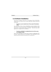
Chapter 3 3.2 Software Installation Software Setup # The drivers can be installed from CD by using CD Installation Utility: # The drivers CAN NOT be installed directly from CD by using CD Installation Utility: 3-2
Chapter 3 3.2 Software Installation Software Setup # The drivers can be installed from CD by using CD Installation Utility: # The drivers CAN NOT be installed directly from CD by using CD Installation Utility: 3-2
M6VCG user's manual
Page 78
... of manual). Re-install applications and data using backup disks. 4-3 When attempting to run Check cable running from the FDISK utility described disk to do so the hard Support. Run the FDISK program, Backing up onto Hard time. Hard Disk boot program has been destroyed. check the drive type in the HARD DISK section board. the Standard CMOS Setup (see is scrambled. if Contact Technical unable to disk controller in DRIVE SPECIFICATION. disk may be...
... of manual). Re-install applications and data using backup disks. 4-3 When attempting to run Check cable running from the FDISK utility described disk to do so the hard Support. Run the FDISK program, Backing up onto Hard time. Hard Disk boot program has been destroyed. check the drive type in the HARD DISK section board. the Standard CMOS Setup (see is scrambled. if Contact Technical unable to disk controller in DRIVE SPECIFICATION. disk may be...
M6VCG user's manual
Page 80
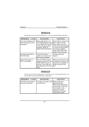
... expansion card. Chapter 4 Trouble Shooting No power to change pin settings. See the documentation that will assist you in doing this. Many expansion devices come with proprietary software that came with the new card in setup. 4-5 Make sure correct information is in order to monitor. Replace any incorrect information. Check the configuration program. Review system's equipment . Incorrect information entered into the configuration (setup) program. All or part of...
... expansion card. Chapter 4 Trouble Shooting No power to change pin settings. See the documentation that will assist you in doing this. Many expansion devices come with proprietary software that came with the new card in setup. 4-5 Make sure correct information is in order to monitor. Replace any incorrect information. Check the configuration program. Review system's equipment . Incorrect information entered into the configuration (setup) program. All or part of...
M6VCG user's manual
Page 81
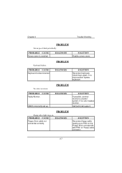
Chapter 4 Trouble Shooting No power to computer. See instructions above . Reboot computer. Network card I /O address on display card. Check jumper and switch settings on network card if applicable. Monitor not connected to monitor. Memory problem, display card jumpers not set correctly. Make sure monitor is connected to display card, change I /O address conflict. Reinstall memory, make sure that all memory modules are installed in correct sockets. Use anti-virus programs (mcAfee, E-Prot, etc) to system. Check the power connectors to monitor and to detect and clean...
Chapter 4 Trouble Shooting No power to computer. See instructions above . Reboot computer. Network card I /O address on display card. Check jumper and switch settings on network card if applicable. Monitor not connected to monitor. Memory problem, display card jumpers not set correctly. Make sure monitor is connected to display card, change I /O address conflict. Reinstall memory, make sure that all memory modules are installed in correct sockets. Use anti-virus programs (mcAfee, E-Prot, etc) to system. Check the power connectors to monitor and to detect and clean...
M6VCG user's manual
Page 82
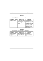
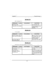
Disable screen saver. Faulty Monitor. Floppy Drive cable not connected correctly. Check keys again, if no color replace monitor. If possible, connect monitor to another system. Call technical support. Reconnect keyboard. Chapter 4 Trouble Shooting Screen saver is disconnected. If no improvement replace keyboard. Keyboard is enabled. Reconnect floppy cable making sure PIN1 on the Floppy Drive corresponds with PIN1 on Floppy cable connector. 4-7 CMOS incorrectly set up.
Disable screen saver. Faulty Monitor. Floppy Drive cable not connected correctly. Check keys again, if no color replace monitor. If possible, connect monitor to another system. Call technical support. Reconnect keyboard. Chapter 4 Trouble Shooting Screen saver is disconnected. If no improvement replace keyboard. Keyboard is enabled. Reconnect floppy cable making sure PIN1 on the Floppy Drive corresponds with PIN1 on Floppy cable connector. 4-7 CMOS incorrectly set up.
M6VCG user's manual
Page 83
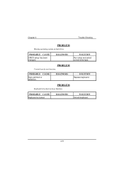
Hard Drive cable not connected properly. Master/Slave jumpers not set correctly. Boot from drive A: using DOS system disk. Check Hard Drive cable. Hard Drives not compatible / different manufacturers. Input correct information to SETUP program. Floppy disk not formatted. Try new floppy disk Format floppy disk (type FORMAT A:type ENTER)>. Run SETUP program and select correct drive types. Set Master/Slave jumpers correctly. Chapter 4 Trouble Shooting Bad floppy disk. Call Drive manufacturers for compatibility with other drives. 4-8 SETUP program does not have correct...
Hard Drive cable not connected properly. Master/Slave jumpers not set correctly. Boot from drive A: using DOS system disk. Check Hard Drive cable. Hard Drives not compatible / different manufacturers. Input correct information to SETUP program. Floppy disk not formatted. Try new floppy disk Format floppy disk (type FORMAT A:type ENTER)>. Run SETUP program and select correct drive types. Set Master/Slave jumpers correctly. Chapter 4 Trouble Shooting Bad floppy disk. Call Drive manufacturers for compatibility with other drives. 4-8 SETUP program does not have correct...
M6VCG user's manual
Page 84
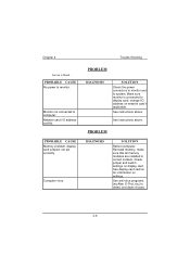
Keys jammed or defective. Chapter 4 CMOS setup has been changed. Keyboard is locked. Unlock keyboard. 4-9 Replace keyboard. Trouble Shooting Run setup and select correct drive type.
Keys jammed or defective. Chapter 4 CMOS setup has been changed. Keyboard is locked. Unlock keyboard. 4-9 Replace keyboard. Trouble Shooting Run setup and select correct drive type.


