
M5ATD user's manual
Page 11
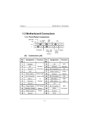
Pin Assignment Function Pin No. No. 1 Speaker 14 2 NC Speaker 15 3 Ground Connector 16 4 +5V 17 5 Power LED(+) Power LED 18 6 No Connection /Green LED 19 7 LED (-) & 20 8 Key lock Keylock 21 9 Ground 22 10 Power Switch ATX Power 23 11 Standby Voltage Button 24 12 Reset Control Reset 25 13 Ground 26 Assignment +5V Ground No Connection Green Control Ground No Connection HDD LED(-) HDD LED(+) +5V No Connection IRRX Ground IRTX Function VCC Ground NC Green Switch NC HDD LED IrDA Connector
Pin Assignment Function Pin No. No. 1 Speaker 14 2 NC Speaker 15 3 Ground Connector 16 4 +5V 17 5 Power LED(+) Power LED 18 6 No Connection /Green LED 19 7 LED (-) & 20 8 Key lock Keylock 21 9 Ground 22 10 Power Switch ATX Power 23 11 Standby Voltage Button 24 12 Reset Control Reset 25 13 Ground 26 Assignment +5V Ground No Connection Green Control Ground No Connection HDD LED(-) HDD LED(+) +5V No Connection IRRX Ground IRTX Function VCC Ground NC Green Switch NC HDD LED IrDA Connector
M5ATD user's manual
Page 27
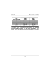
Total Memory Size (MB) 80M 96M 128M 192M 256M Bank 0 DIMM 1 16M x 1 pc 32M x 1 pc 64M x 1 pc 128M x 1pc 128M x 1pc Bank 1 DIMM 2 64M x 1 pc 64M x 1 pc 64M x 1 pc 64M x 1pc 128M x 1pc *Each Bank can be installed and worked individually, the mainboard provides optimal performance and free choices depending on your needs. *The list show above for DRAM configuration is just for reference.
Total Memory Size (MB) 80M 96M 128M 192M 256M Bank 0 DIMM 1 16M x 1 pc 32M x 1 pc 64M x 1 pc 128M x 1pc 128M x 1pc Bank 1 DIMM 2 64M x 1 pc 64M x 1 pc 64M x 1 pc 64M x 1pc 128M x 1pc *Each Bank can be installed and worked individually, the mainboard provides optimal performance and free choices depending on your needs. *The list show above for DRAM configuration is just for reference.
M5ATD user's manual
Page 31
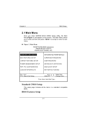
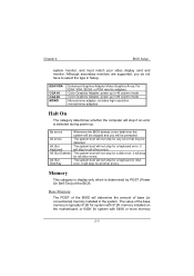
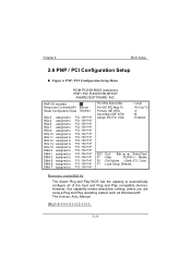
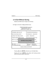
Chapter 2 BIOS Setup Figure 1 ! Enter STANDARD CMOS SETUP BIOS FEATURES SETUP CHIPSET FEATURES SETUP POWER MANAGEMENT SETUP PNP / PCI CONFIGURATION LOAD SETUP DEFAULTS SUPERVISOR PASSWORD USER PASSWORD IDE HDD AUTO DETECTION SAVE & EXIT SETUP EXIT WITHOUT SAVING Esc : Quit F10 : Save & Exit Setup (Shift) F2 : Select Item : Change Color Time, Date, Hard Disk Type... 2-
Chapter 2 BIOS Setup Figure 1 ! Enter STANDARD CMOS SETUP BIOS FEATURES SETUP CHIPSET FEATURES SETUP POWER MANAGEMENT SETUP PNP / PCI CONFIGURATION LOAD SETUP DEFAULTS SUPERVISOR PASSWORD USER PASSWORD IDE HDD AUTO DETECTION SAVE & EXIT SETUP EXIT WITHOUT SAVING Esc : Quit F10 : Save & Exit Setup (Shift) F2 : Select Item : Change Color Time, Date, Hard Disk Type... 2-
M5ATD user's manual
Page 34
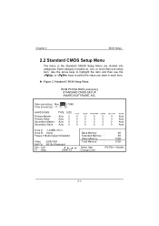
Date (mm:dd:yy) : Mon, Aug 3 1998 Time (hh:mm:ss) : 11 : 37 : 30 HARD DISKS TYPE SIZE Primary Master : Auto 0 0 0 Primary Slave : Auto 0 0 0 Secondary Master : Auto 0 0 0 Secondary Slave : Auto 0 0 0 0 0 0 Auto 0 0 0 Auto 0 0 0 Auto 0 0 0 Auto Drive A :1.44MB, 3.5 in. Chapter 2 BIOS Setup ! Drive B :None Floppy 3 Mode Support:Disabled Video :EGA/VGA Halt On :All, But Keyboard Esc : Quit F1 : Help (Shift) F2 Base Memory : Extended Memory : Other Memory : Total Memory : 0K 0K 512K 512K : Select Item : Change Color PU/PD/+/-:Modify 2-
Date (mm:dd:yy) : Mon, Aug 3 1998 Time (hh:mm:ss) : 11 : 37 : 30 HARD DISKS TYPE SIZE Primary Master : Auto 0 0 0 Primary Slave : Auto 0 0 0 Secondary Master : Auto 0 0 0 Secondary Slave : Auto 0 0 0 0 0 0 Auto 0 0 0 Auto 0 0 0 Auto 0 0 0 Auto Drive A :1.44MB, 3.5 in. Chapter 2 BIOS Setup ! Drive B :None Floppy 3 Mode Support:Disabled Video :EGA/VGA Halt On :All, But Keyboard Esc : Quit F1 : Help (Shift) F2 Base Memory : Extended Memory : Other Memory : Total Memory : 0K 0K 512K 512K : Select Item : Change Color PU/PD/+/-:Modify 2-
M5ATD user's manual
Page 37
... detected. Chapter 2 BIOS Setup Enhanced Graphics Adapter/Video Graphics Array. The system boot will not stop for a disk error, it will not stop for any error that may be prompted. The system boot will stop for all other errors. The system boot will not stop for a keyboard error, it will stop for all other errors. For EGA, VGA, SEGA, or PGA monitor adapters. The system boot will not...
... detected. Chapter 2 BIOS Setup Enhanced Graphics Adapter/Video Graphics Array. The system boot will not stop for a disk error, it will not stop for any error that may be prompted. The system boot will stop for all other errors. The system boot will not stop for a keyboard error, it will stop for all other errors. For EGA, VGA, SEGA, or PGA monitor adapters. The system boot will not...
M5ATD user's manual
Page 39
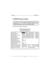
... : Disabled Swap Floppy Drive : Disabled D8000-DBFFF Shadow : Disabled Boot Up Floppy Seek : Enabled DC000-DFFFF Shadow : Disabled Boot Up NumLock Status : On Gate A20 Option : Fast Typematic Rate Setting : Disabled Typematic Rate (Chars/Sec) : 6 Typematic Delay (Msec) : 250 Security Option : Setup PS/2 mouse function control : Enabled PCI/VGA Palette Snoop : Disabled ESC : Quit : Select Item : Non-OS2 F1 : Help PU/PD/+/- : Modify :Disabled F5 : Old Values F2 : Color : No F7 : Load Setup Defaults...
... : Disabled Swap Floppy Drive : Disabled D8000-DBFFF Shadow : Disabled Boot Up Floppy Seek : Enabled DC000-DFFFF Shadow : Disabled Boot Up NumLock Status : On Gate A20 Option : Fast Typematic Rate Setting : Disabled Typematic Rate (Chars/Sec) : 6 Typematic Delay (Msec) : 250 Security Option : Setup PS/2 mouse function control : Enabled PCI/VGA Palette Snoop : Disabled ESC : Quit : Select Item : Non-OS2 F1 : Help PU/PD/+/- : Modify :Disabled F5 : Old Values F2 : Color : No F7 : Load Setup Defaults...
M5ATD user's manual
Page 46
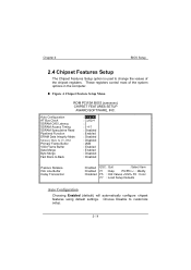
Auto Configuration AT Bus Clock SDRAM CAS Latency SDRAM Access Timing SDRAM Speculative Read Pipelined Function DRAM Data Integrity Mode Primary Frame Buffer VGA Frame Buffer Data Merge Byte Merge Fast Back-to-Back : Enabled : CLK2/4 : 3 : 3-4-7 : Disabled : Enabled : Disabled : Disabled : 2MB : Enabled : Enabled : Disabled : Disabled Passive Release ISA Line Buffer Delay Transaction : Enabled : Enabled : Disabled ESC : Quit : Select Item F1 : Help PU/PD/+/- : Modify F5 : Old Values F2 : Color F7 : Load Setup Defaults Enabled 2- Chapter 2 BIOS Setup !
Auto Configuration AT Bus Clock SDRAM CAS Latency SDRAM Access Timing SDRAM Speculative Read Pipelined Function DRAM Data Integrity Mode Primary Frame Buffer VGA Frame Buffer Data Merge Byte Merge Fast Back-to-Back : Enabled : CLK2/4 : 3 : 3-4-7 : Disabled : Enabled : Disabled : Disabled : 2MB : Enabled : Enabled : Disabled : Disabled Passive Release ISA Line Buffer Delay Transaction : Enabled : Enabled : Disabled ESC : Quit : Select Item F1 : Help PU/PD/+/- : Modify F5 : Old Values F2 : Color F7 : Load Setup Defaults Enabled 2- Chapter 2 BIOS Setup !
M5ATD user's manual
Page 50
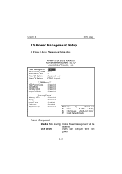
BIOS Setup Power Management PM Control by APM MODEM Use IRQ Video Off Option Video Off Method : Disabled : Yes : 3 : Suspend :DPMS Support ** PM Monitor ** HDD Power Down : Disabled Doze Mode : Disabled Standby Mode : Disabled Suspend Mode : Disabled **Standby Events** Primary HDD : Disabled Floppy : Disabled Serial Ports Keyboard Parallel Ports : Enabled : Enabled : Disabled ESC : Quit : Select Item F1 : Help PU/PD/+/- : Modify F5 : Old Values F2 : Color F7 : Load Setup Defaults Disable User Define 2- Chapter 2 !
BIOS Setup Power Management PM Control by APM MODEM Use IRQ Video Off Option Video Off Method : Disabled : Yes : 3 : Suspend :DPMS Support ** PM Monitor ** HDD Power Down : Disabled Doze Mode : Disabled Standby Mode : Disabled Suspend Mode : Disabled **Standby Events** Primary HDD : Disabled Floppy : Disabled Serial Ports Keyboard Parallel Ports : Enabled : Enabled : Disabled ESC : Quit : Select Item F1 : Help PU/PD/+/- : Modify F5 : Old Values F2 : Color F7 : Load Setup Defaults Disable User Define 2- Chapter 2 !
M5ATD user's manual
Page 54
Chapter 2 BIOS Setup ! PNP OS Installed Resources Controlled BY Reset Configuration Data IRQ-3 IRQ-4 IRQ-5 IRQ-7 IRQ-9 IRQ-10 IRQ-11 IRQ-12 IRQ-14 IRQ-15 DMA-0 DMA-1 DMA-3 DMA-5 DMA-6 DMA-7 assigned to assigned ... assigned to assigned to assigned to assigned to assigned to assigned to assigned to assigned to assigned to assigned to PCI IRQ Actived By Pci IDE IRQ Map To Primary IDE INT# Secondary IDE INT# Assign IRQ For VGA : Level : A : B : Enabled ESC : Quit : Select Item F1 : Help PU/PD/+/- : Modify F5 : Old Values F2 : Color F7 : Load Setup Defaults 2-
Chapter 2 BIOS Setup ! PNP OS Installed Resources Controlled BY Reset Configuration Data IRQ-3 IRQ-4 IRQ-5 IRQ-7 IRQ-9 IRQ-10 IRQ-11 IRQ-12 IRQ-14 IRQ-15 DMA-0 DMA-1 DMA-3 DMA-5 DMA-6 DMA-7 assigned to assigned ... assigned to assigned to assigned to assigned to assigned to assigned to assigned to assigned to assigned to assigned to PCI IRQ Actived By Pci IDE IRQ Map To Primary IDE INT# Secondary IDE INT# Assign IRQ For VGA : Level : A : B : Enabled ESC : Quit : Select Item F1 : Help PU/PD/+/- : Modify F5 : Old Values F2 : Color F7 : Load Setup Defaults 2-
M5ATD user's manual
Page 58
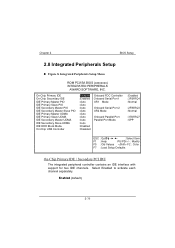
...PIO IDE Secondary Master Slave PIO IDE Primary Master UDMA IDE Primary Slave UDMA IDE Secondary Master UDMA IDE Secondary Slave UDMA IDE HDD Block Mode On-Chip USB Controller : Enabled : Enabled : Auto : Auto : Auto : Auto : Auto : Auto : Auto : Auto : Enabled : Disabled Onboard FDC Controller Onboard Serial Port 1 UR1 Mode Onboard Serial Port 2 UR2 Mode Onboard Parallel Port Parallel Port Mode : Enabled : 3F8/IRQ4 : Normal : 2F8/IRQ3 : Normal : 378/IRQ7 : SPP ESC : Quit : Select Item F1 : Help PU/PD/+/- : Modify F5 : Old Values F2 : Color F7 : Load Setup Defaults Enabled 2- Chapter...
...PIO IDE Secondary Master Slave PIO IDE Primary Master UDMA IDE Primary Slave UDMA IDE Secondary Master UDMA IDE Secondary Slave UDMA IDE HDD Block Mode On-Chip USB Controller : Enabled : Enabled : Auto : Auto : Auto : Auto : Auto : Auto : Auto : Auto : Enabled : Disabled Onboard FDC Controller Onboard Serial Port 1 UR1 Mode Onboard Serial Port 2 UR2 Mode Onboard Parallel Port Parallel Port Mode : Enabled : 3F8/IRQ4 : Normal : 2F8/IRQ3 : Normal : 378/IRQ7 : SPP ESC : Quit : Select Item F1 : Help PU/PD/+/- : Modify F5 : Old Values F2 : Color F7 : Load Setup Defaults Enabled 2- Chapter...
M5ATD user's manual
Page 65
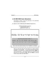
Chapter 2 ! BIOS Setup HARD DISKS TYPE SIZE Primary Master :User 343 665 16 65535 664 63 NORMAL OPTIONS Select Primary Slave Option (N=Skip) N Note : Some Oses (like SCO-UNIX) must use "NORMAL" for installation ESC : Skip "Y" Esc Enter Enter 2-
Chapter 2 ! BIOS Setup HARD DISKS TYPE SIZE Primary Master :User 343 665 16 65535 664 63 NORMAL OPTIONS Select Primary Slave Option (N=Skip) N Note : Some Oses (like SCO-UNIX) must use "NORMAL" for installation ESC : Skip "Y" Esc Enter Enter 2-
M5ATD user's manual
Page 66
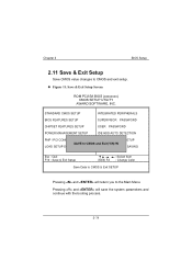
Chapter 2 BIOS Setup ! STANDARD CMOS SETUP BIOS FEATURES SETUP CHIPSET FEATURES SETUP POWER MANAGEMENT SETUP PNP / PCI CONFIGUF LOAD SETUP DEFAULTS INTEGRATED PERIPHERALS SUPERVISOR PASSWORD USER PASSWORD IDE HDD AUTO DETECTION EXIT WITHOUT SAVI ETUP SAVING Esc : Quit F10 : Save & Exit Setup : Select Item (Shift) F2 : Change Color Save Data to CMOS & Exit SETUP 2-
Chapter 2 BIOS Setup ! STANDARD CMOS SETUP BIOS FEATURES SETUP CHIPSET FEATURES SETUP POWER MANAGEMENT SETUP PNP / PCI CONFIGUF LOAD SETUP DEFAULTS INTEGRATED PERIPHERALS SUPERVISOR PASSWORD USER PASSWORD IDE HDD AUTO DETECTION EXIT WITHOUT SAVI ETUP SAVING Esc : Quit F10 : Save & Exit Setup : Select Item (Shift) F2 : Change Color Save Data to CMOS & Exit SETUP 2-
M5ATD user's manual
Page 67
STANDARD CMOS SETUP BIOS FEATURES SETUP CHIPSET FEATURES SETUP POWER MANAGEMENT SETUP PNP / PCI CONFIGUF LOAD SETUP DEFAULTS INTEGRATED PERIPHERALS SUPERVISOR PASSWORD USER PASSWORD IDE HDD AUTO DETECTION EXIT WITHOUT SAVI TUP AVING Esc : Quit F10 : Save & Exit Setup : Select Item (Shift) F2 : Change Color Abandon All Data & Exit SETUP 2- Chapter 2 BIOS Setup !
STANDARD CMOS SETUP BIOS FEATURES SETUP CHIPSET FEATURES SETUP POWER MANAGEMENT SETUP PNP / PCI CONFIGUF LOAD SETUP DEFAULTS INTEGRATED PERIPHERALS SUPERVISOR PASSWORD USER PASSWORD IDE HDD AUTO DETECTION EXIT WITHOUT SAVI TUP AVING Esc : Quit F10 : Save & Exit Setup : Select Item (Shift) F2 : Change Color Abandon All Data & Exit SETUP 2- Chapter 2 BIOS Setup !

M5ATD user's manual
Page 72
... expansion socket. Take Using even pressure on the motherboard. card. Disconnect the cables Support. Turn computer off . from one of the slot on dislodged from expansion cover off computer. both ends of the floppy drives. Repeat until you have located defective unit. Remove an expansion card Make sure expansion card is partially Turn off system unit. Check all expansion cards expansion card, press to see if the keyboard...
... expansion socket. Take Using even pressure on the motherboard. card. Disconnect the cables Support. Turn computer off . from one of the slot on dislodged from expansion cover off computer. both ends of the floppy drives. Repeat until you have located defective unit. Remove an expansion card Make sure expansion card is partially Turn off system unit. Check all expansion cards expansion card, press to see if the keyboard...
M5ATD user's manual
Page 73
... Standard CMOS Setup (see is scrambled. if Contact Technical unable to disk controller in the HARD DISK section board. All HARD DRIVE section of Hard Disks are securely plugged message, INVALID in DRIVE SPECIFICATION. Damaged Hard Disk or Disk Controller. Run the FDISK program, Backing up onto Hard time. Drive. check the drive type in ; disk may be defective. Copy data that breaking down at any was backed up the hard drive format the hard drive (see HARD DISK...
... Standard CMOS Setup (see is scrambled. if Contact Technical unable to disk controller in the HARD DISK section board. All HARD DRIVE section of Hard Disks are securely plugged message, INVALID in DRIVE SPECIFICATION. Damaged Hard Disk or Disk Controller. Run the FDISK program, Backing up onto Hard time. Drive. check the drive type in ; disk may be defective. Copy data that breaking down at any was backed up the hard drive format the hard drive (see HARD DISK...

M5ATD user's manual
Page 75
... monitor. All or part of the system may not work but a mouse or COM port may be inoperable. The new card may work Change the interrupt or RAM address on the new expansion card. Format disk in the AT type computer insert disk into the IBM PS/2 and copy the files you in doing this. computer. No power to change pin settings. Many expansion devices come with proprietary software...
... monitor. All or part of the system may not work but a mouse or COM port may be inoperable. The new card may work Change the interrupt or RAM address on the new expansion card. Format disk in the AT type computer insert disk into the IBM PS/2 and copy the files you in doing this. computer. No power to change pin settings. Many expansion devices come with proprietary software...

M5ATD user's manual
Page 76
Chapter 4 Trouble Shooting Incorrect information entered into the configuration (setup) program. Check the configuration program. Monitor not connected to system. Check the power connectors to monitor and to computer. Review system's equipment . Network card I /O address on network card if applicable See instructions above . Make sure correct information is connected to monitor. See instructions above . Make sure monitor is in setup. No power to display card, change I /O address conflict. Replace any incorrect information.
Chapter 4 Trouble Shooting Incorrect information entered into the configuration (setup) program. Check the configuration program. Monitor not connected to system. Check the power connectors to monitor and to computer. Review system's equipment . Network card I /O address on network card if applicable See instructions above . Make sure correct information is connected to monitor. See instructions above . Make sure monitor is in setup. No power to display card, change I /O address conflict. Replace any incorrect information.

M5ATD user's manual
Page 77
Reinstall memory, make sure that all memory modules are installed in correct sockets. See display card section for information on display card. Trouble Shooting Reboot computer. Check jumper and switch settings on settings. Chapter 4 Memory problem, display card jumpers not set correctly. Use anti-virus programs (mcAfee, E-Prot, etc) to detect and clean viruses. Disable screen saver. Screen saver is enabled. Computer virus.
Reinstall memory, make sure that all memory modules are installed in correct sockets. See display card section for information on display card. Trouble Shooting Reboot computer. Check jumper and switch settings on settings. Chapter 4 Memory problem, display card jumpers not set correctly. Use anti-virus programs (mcAfee, E-Prot, etc) to detect and clean viruses. Disable screen saver. Screen saver is enabled. Computer virus.

M5ATD user's manual
Page 80
Set Master/Slave jumpers correctly. Hard Drives not compatible / different manufacturers. Trouble Shooting Boot from drive A: using DOS system disk. Input correct information to SETUP program. Run SETUP program and select correct drive types. Call Drive manufacturers for compatibility with other drives. Master/Slave jumpers not set correctly. Check Hard Drive cable. Chapter 4 SETUP program does not have correct information. Hard Drive cable not connected properly.
Set Master/Slave jumpers correctly. Hard Drives not compatible / different manufacturers. Trouble Shooting Boot from drive A: using DOS system disk. Input correct information to SETUP program. Run SETUP program and select correct drive types. Call Drive manufacturers for compatibility with other drives. Master/Slave jumpers not set correctly. Check Hard Drive cable. Chapter 4 SETUP program does not have correct information. Hard Drive cable not connected properly.

M5ATD user's manual
Page 81
Chapter 4 CMOS setup has been changed. Keys jammed or defective. Keyboard is locked. Replace keyboard. Unlock keyboard Trouble Shooting Run setup and select correct drive type.
Chapter 4 CMOS setup has been changed. Keys jammed or defective. Keyboard is locked. Replace keyboard. Unlock keyboard Trouble Shooting Run setup and select correct drive type.


