
User Manual
Page 8
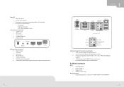
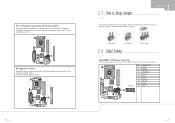
... Interface. 4 Provides the most commonly used legacy Super I /O Connectors 4 1 SPDIF-In port. 4 1 MIC-In port. 4 1 Line-Out port. 4 1 1394A Firewire port. 4 2 USB 2.0 ports. BIOS & Software BIOS 4 Award legal BIOS. 4 Supports APM1.2. 4 Supports ACPI. 4 Supports USB Function. H/W Monitor. - ITE's "Smart Guardian" function. Front Panel I /O functionality. 4 Environment Control initiatives: - PS/2 Mouse COM 1394A Audio-out...
... Interface. 4 Provides the most commonly used legacy Super I /O Connectors 4 1 SPDIF-In port. 4 1 MIC-In port. 4 1 Line-Out port. 4 1 1394A Firewire port. 4 2 USB 2.0 ports. BIOS & Software BIOS 4 Award legal BIOS. 4 Supports APM1.2. 4 Supports ACPI. 4 Supports USB Function. H/W Monitor. - ITE's "Smart Guardian" function. Front Panel I /O functionality. 4 Environment Control initiatives: - PS/2 Mouse COM 1394A Audio-out...
User Manual
Page 9
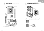
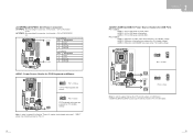
...FIO4 IDE1 JSFAN1 JUSBV1 Codec FIO2 FIO3 JCDIN1 JCMOS1 JSATA2 JSATA1 COM VGA 2.3 Installing Central Processing Unit (CPU) Super I /O BIOS Grantsdale-G BAT1 JATXPWR3 Giga LAN IEEE1394 Chip JKBV1 JKBMS1 Note: represents the 1st pin. 2.2 Layout & Components JATXPWR2 J1394B1 JUSB5 JUSB4... JOUT1 JMIC1 JSPDIFI1 FIO1S LGA775 CPU1 Super I /O BIOS Grantsdale-G CPU1 BAT1 Intel ICH6R Giga LAN IEEE1394 Chip Codec Special Notice: Remove Pin Cap before installation, and make good preservation ...
...FIO4 IDE1 JSFAN1 JUSBV1 Codec FIO2 FIO3 JCDIN1 JCMOS1 JSATA2 JSATA1 COM VGA 2.3 Installing Central Processing Unit (CPU) Super I /O BIOS Grantsdale-G BAT1 JATXPWR3 Giga LAN IEEE1394 Chip JKBV1 JKBMS1 Note: represents the 1st pin. 2.2 Layout & Components JATXPWR2 J1394B1 JUSB5 JUSB4... JOUT1 JMIC1 JSPDIFI1 FIO1S LGA775 CPU1 Super I /O BIOS Grantsdale-G CPU1 BAT1 Intel ICH6R Giga LAN IEEE1394 Chip Codec Special Notice: Remove Pin Cap before installation, and make good preservation ...
User Manual
Page 10
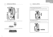
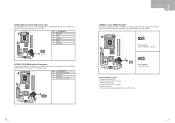
...to complete the installation. Step 2: Look for System Fan Pin Assignment 1 Ground 2 Smart Fan Control 3 FAN RPM rate sense Super I /O BIOS Grantsdale-G BAT1 Intel ICH6R Giga LAN IEEE1394 Chip Codec 31 JSFAN1: Power Source for the black cut edge. JCFAN1: Power Source for CPU Fan ...Pin Assignment 1 Ground 2 Power 3 FAN RPM rate sense Super I /O BIOS Grantsdale-G BAT1 Intel ICH6R Giga LAN IEEE1394 Chip Codec JSFAN1 31 Step 2-1: Step 2-2: Step 3: Hold the CPU down firmly, and then close the ...
...to complete the installation. Step 2: Look for System Fan Pin Assignment 1 Ground 2 Smart Fan Control 3 FAN RPM rate sense Super I /O BIOS Grantsdale-G BAT1 Intel ICH6R Giga LAN IEEE1394 Chip Codec 31 JSFAN1: Power Source for the black cut edge. JCFAN1: Power Source for CPU Fan ...Pin Assignment 1 Ground 2 Power 3 FAN RPM rate sense Super I /O BIOS Grantsdale-G BAT1 Intel ICH6R Giga LAN IEEE1394 Chip Codec JSFAN1 31 Step 2-1: Step 2-2: Step 3: Hold the CPU down firmly, and then close the ...
User Manual
Page 11
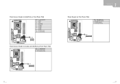
Super I /O BIOS Grantsdale-G BAT1 Intel ICH6R Giga LAN IEEE1394 Chip Codec FDD1 16 15 21 IDE1: Hard Disk Connector The motherboard has a 32-bit Enhanced PCI IDE ... floppy disk connector that the notch on the DIMM matches the break on the Slot. 2. This connector supports the provided floppy drive ribbon cables Super I /O BIOS Grantsdale-G BAT1 Intel ICH6R Giga LAN IEEE1394 Chip Codec IDE1 2 40 1 39 Unlock a DIMM slot by pressing the retaining clips outward. 2.5 Installing System Memory DDRA1...
Super I /O BIOS Grantsdale-G BAT1 Intel ICH6R Giga LAN IEEE1394 Chip Codec FDD1 16 15 21 IDE1: Hard Disk Connector The motherboard has a 32-bit Enhanced PCI IDE ... floppy disk connector that the notch on the DIMM matches the break on the Slot. 2. This connector supports the provided floppy drive ribbon cables Super I /O BIOS Grantsdale-G BAT1 Intel ICH6R Giga LAN IEEE1394 Chip Codec IDE1 2 40 1 39 Unlock a DIMM slot by pressing the retaining clips outward. 2.5 Installing System Memory DDRA1...
User Manual
Page 12
... SB Volt. 5 Ground 6 +5V 7 +3.3V 8 Ground 9 PS_ON 10 +12V 11 Ground 12 +5V Giga LAN IEEE1394 Chip Codec 7 12 Super I /O BIOS Grantsdale-G BAT1 Intel ICH6R Giga LAN IEEE1394 Chip Codec PCI-E x16_1 2.7 How to Setup Jumpers The illustration shows how to connect 12-pin power connector... opened Pin closed 2.8 Detail Setting Pin1-2 closed JATXPWR1: ATX Power Connector This connector allows user to set up jumpers. Super I/O BIOS Grantsdale-G BAT1 Intel ICH6R Giga LAN IEEE1394 Chip Codec PCI1 PCI-Express x16 slot: Maximum theoretical realized bandwidth of 8GB/s totally. 4...
... SB Volt. 5 Ground 6 +5V 7 +3.3V 8 Ground 9 PS_ON 10 +12V 11 Ground 12 +5V Giga LAN IEEE1394 Chip Codec 7 12 Super I /O BIOS Grantsdale-G BAT1 Intel ICH6R Giga LAN IEEE1394 Chip Codec PCI-E x16_1 2.7 How to Setup Jumpers The illustration shows how to connect 12-pin power connector... opened Pin closed 2.8 Detail Setting Pin1-2 closed JATXPWR1: ATX Power Connector This connector allows user to set up jumpers. Super I/O BIOS Grantsdale-G BAT1 Intel ICH6R Giga LAN IEEE1394 Chip Codec PCI1 PCI-Express x16 slot: Maximum theoretical realized bandwidth of 8GB/s totally. 4...
User Manual
Page 13
...-G BAT1 Intel ICH6R Giga LAN IEEE1394 Chip Codec 13 JKBV1 13 Pin 1-2 Close +5V for PS/2 Keyboard and Mouse Super I /O BIOS Grantsdale-G BAT1 Intel ICH6R Giga LAN IEEE1394 Chip Codec Pin 1-2 Close 31 JUSBV2 JUSBV3 3 1 JUSBV1 31 31 3 1 Pin 2-3 close ...JUSBV2: USB ports at front panel. JUSBV3: USB ports at JRJ45USB1. JATXPWR2 21 43 JATXPWR2 Pin Assignment 1 +12V 2 +12V 3 Ground 4 Ground Super I/O BIOS Grantsdale-G BAT1 Intel ICH6R Giga LAN IEEE1394 Chip Codec 34 12 JATXPWR3 JATXPWR3 Pin Assignment 1 +12V 2 +12V 3 Ground 4 Ground JKBV1: Power Source Header ...
...-G BAT1 Intel ICH6R Giga LAN IEEE1394 Chip Codec 13 JKBV1 13 Pin 1-2 Close +5V for PS/2 Keyboard and Mouse Super I /O BIOS Grantsdale-G BAT1 Intel ICH6R Giga LAN IEEE1394 Chip Codec Pin 1-2 Close 31 JUSBV2 JUSBV3 3 1 JUSBV1 31 31 3 1 Pin 2-3 close ...JUSBV2: USB ports at front panel. JUSBV3: USB ports at JRJ45USB1. JATXPWR2 21 43 JATXPWR2 Pin Assignment 1 +12V 2 +12V 3 Ground 4 Ground Super I/O BIOS Grantsdale-G BAT1 Intel ICH6R Giga LAN IEEE1394 Chip Codec 34 12 JATXPWR3 JATXPWR3 Pin Assignment 1 +12V 2 +12V 3 Ground 4 Ground JKBV1: Power Source Header ...
User Manual
Page 14
... connect the audio source from the variety devices, like CD-ROM, DVD-ROM, PCI sound card, PCI TV turner card etc.. Super I /O BIOS Grantsdale-G BAT1 Intel ICH6R Giga LAN IEEE1394 Chip Codec Pin 1-2 Close: Normal Operation (default). JCMOS1 13 13 Pin 2-3 Close: Clear CMOS data.... Set the jumper to "Pin 2-3 close ". 5. Pin Assignment 1 Left Channel Input 2 Ground 3 Ground 4 Right Channel Input Super I/O BIOS Grantsdale-G BAT1 Intel ICH6R Giga LAN IEEE1394 Chip Codec JCDIN1 14 20 JCMOS1: Clear CMOS Header4 By placing the jumper on the AC. 6. Powers on...
... connect the audio source from the variety devices, like CD-ROM, DVD-ROM, PCI sound card, PCI TV turner card etc.. Super I /O BIOS Grantsdale-G BAT1 Intel ICH6R Giga LAN IEEE1394 Chip Codec Pin 1-2 Close: Normal Operation (default). JCMOS1 13 13 Pin 2-3 Close: Clear CMOS data.... Set the jumper to "Pin 2-3 close ". 5. Pin Assignment 1 Left Channel Input 2 Ground 3 Ground 4 Right Channel Input Super I/O BIOS Grantsdale-G BAT1 Intel ICH6R Giga LAN IEEE1394 Chip Codec JCDIN1 14 20 JCMOS1: Clear CMOS Header4 By placing the jumper on the AC. 6. Powers on...
User Manual
Page 15
Power Source Header for USB Ports at Front Panel: FIO4 Super I/O BIOS Grantsdale-G Pin Assignment 1 Key 2 NC 3 Ground 4 Ground 5 USB+ 6 USB+ 7 USB8 USB9 +5V (fused) 10 +5V (fused) BAT1 Intel ICH6R Giga LAN IEEE1394 Chip Codec FIO4 ...19 2 10 Power Source Header for Audio and 1394 Ports at Front Panel: FIO3 Pin Assignment 1~10 1394 Header 11~20 Audio Control Super I/O BIOS Grantsdale-G BAT1 Intel ICH6R Giga LAN IEEE1394 Chip Codec FIO3 1 19 2 20 22 Power Header for Front Panel: FIO2 Pin 1~10 11~20 21~28...
Power Source Header for USB Ports at Front Panel: FIO4 Super I/O BIOS Grantsdale-G Pin Assignment 1 Key 2 NC 3 Ground 4 Ground 5 USB+ 6 USB+ 7 USB8 USB9 +5V (fused) 10 +5V (fused) BAT1 Intel ICH6R Giga LAN IEEE1394 Chip Codec FIO4 ...19 2 10 Power Source Header for Audio and 1394 Ports at Front Panel: FIO3 Pin Assignment 1~10 1394 Header 11~20 Audio Control Super I/O BIOS Grantsdale-G BAT1 Intel ICH6R Giga LAN IEEE1394 Chip Codec FIO3 1 19 2 20 22 Power Header for Front Panel: FIO2 Pin 1~10 11~20 21~28...

