
I915P-A7 user's manual
Page 4
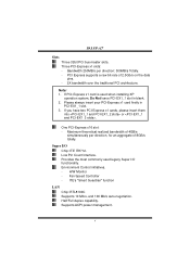
...architecture. ITE's "Smart Guardian" function LAN Chip: RTL8100C Supports 10 Mb/s, and 100 Mb/s auto-negotiation. Low Pin Count Interface. Fan Speed Controller - Supports ACPI power management. 4 One PCI-Express x16 slot: - Environment Control initiatives, - If PCI-Express x1 card is used legacy Super I /O Chip: ITE IT8712. Please always insert your PCI-Express x1 card firstly in blank. 2. H/W Monitor - Note: 1. Super I /O functionality. Half/Full duplex capability. Three PCI-Express x1 slots: - I915P-A7 Slots Three 32bit PCI bus master slots. Provides the...
...architecture. ITE's "Smart Guardian" function LAN Chip: RTL8100C Supports 10 Mb/s, and 100 Mb/s auto-negotiation. Low Pin Count Interface. Fan Speed Controller - Supports ACPI power management. 4 One PCI-Express x16 slot: - Environment Control initiatives, - If PCI-Express x1 card is used legacy Super I /O Chip: ITE IT8712. Please always insert your PCI-Express x1 card firstly in blank. 2. H/W Monitor - Note: 1. Super I /O functionality. Half/Full duplex capability. Three PCI-Express x1 slots: - I915P-A7 Slots Three 32bit PCI bus master slots. Provides the...

I915P-A7 user's manual
Page 5
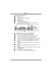
...(SATA) ports. - Integrated RAID 0, RAID 1 and RAID 0+1 for 4 IDE devices. Supports two extra slots for IDE2/IDE3 slot. On-board AC'97 Sound Codec Chip: ALC655 Support 6 channels. Supports two extra slots for 4 IDE devices - Supports two 1394 Firewire ports with RAID function): - IDE Controller (optional) Chip: ITE8211 (without RAID function) - Serial ATA Controller integrated in ICH6. I915P-A7 IEEE 1394 Chip (optional) Chip: VIA VT6307. Compliant with AC'97 Version 2.3 specification. Supports PIO Mode 0~4, Bride Mode and Ultra DMA 33/66/100 Bus Master Mode. Supports PIO Mode...
...(SATA) ports. - Integrated RAID 0, RAID 1 and RAID 0+1 for 4 IDE devices. Supports two extra slots for IDE2/IDE3 slot. On-board AC'97 Sound Codec Chip: ALC655 Support 6 channels. Supports two extra slots for 4 IDE devices - Supports two 1394 Firewire ports with RAID function): - IDE Controller (optional) Chip: ITE8211 (without RAID function) - Serial ATA Controller integrated in ICH6. I915P-A7 IEEE 1394 Chip (optional) Chip: VIA VT6307. Compliant with AC'97 Version 2.3 specification. Supports PIO Mode 0~4, Bride Mode and Ultra DMA 33/66/100 Bus Master Mode. Supports PIO Mode...
I915P-A7 user's manual
Page 6
... Internal On-board I /O Connectors 4 USB 2.0 ports. 1 serial ports (COM2 is optional). 1 parallel port. 1 RJ-45 LAN jack. 1 PS/2 Mouse & Keyboard port. 1 vertical audio port including 1 line-in connector, 1 line connector, and 1 MIC in function (optional). 1 1394A header supports 1 front panel 1394A Firewire port (optional). 1 chassis open header supports PC case-opened warning function. 1 Floppy port supports 2 FDD with 360K, 720K, 1.2M, 1.44M and 2.88Mbytes. 2 USB headers support 4 USB 2.0 ports. 4 serial ATA connectors support 4 SATA devices. 6 I915P-A7 Back Panel I /O Connectors...
... Internal On-board I /O Connectors 4 USB 2.0 ports. 1 serial ports (COM2 is optional). 1 parallel port. 1 RJ-45 LAN jack. 1 PS/2 Mouse & Keyboard port. 1 vertical audio port including 1 line-in connector, 1 line connector, and 1 MIC in function (optional). 1 1394A header supports 1 front panel 1394A Firewire port (optional). 1 chassis open header supports PC case-opened warning function. 1 Floppy port supports 2 FDD with 360K, 720K, 1.2M, 1.44M and 2.88Mbytes. 2 USB headers support 4 USB 2.0 ports. 4 serial ATA connectors support 4 SATA devices. 6 I915P-A7 Back Panel I /O Connectors...
I915P-A7 user's manual
Page 7
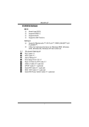
BIOS & Software BIOS Award legal BIOS. Supports USB Function. Offers the highest performance for Windows 98SE, Windows 2000, Windows Me, Windows XP, SCO UNIX etc. 1.2 PACKAGE CHECKLIST FDD Cable X 1 HDD Cable X 1 User's Manual X 1 Fully Setup Driver CD X 1 Rear I/O Panel for ATX Case X 1 USB 2.0 Cable X1 (optional) S/PDIF Cable X 1 (optional) Serial ATA Cable X 1 (optional) IEEE 1394 Cable X 1 (optional) Serial ATA Power Switch Cable X 1 (optional) 7 Supports APM1.2. I915P-A7 B. Supports ACPI. Software Supports Warpspeeder™, 9th Touch™, WINFLASHER™ and FLASHER&#...
BIOS & Software BIOS Award legal BIOS. Supports USB Function. Offers the highest performance for Windows 98SE, Windows 2000, Windows Me, Windows XP, SCO UNIX etc. 1.2 PACKAGE CHECKLIST FDD Cable X 1 HDD Cable X 1 User's Manual X 1 Fully Setup Driver CD X 1 Rear I/O Panel for ATX Case X 1 USB 2.0 Cable X1 (optional) S/PDIF Cable X 1 (optional) Serial ATA Cable X 1 (optional) IEEE 1394 Cable X 1 (optional) Serial ATA Power Switch Cable X 1 (optional) 7 Supports APM1.2. I915P-A7 B. Supports ACPI. Software Supports Warpspeeder™, 9th Touch™, WINFLASHER™ and FLASHER&#...
I915P-A7 user's manual
Page 14
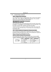
... four hard disk drives. This PCI slot is equipped with transfer rate of 1.5Gb/s. 7 1 Pin Assignment 1 Ground 3 TX5 RX7 Ground Pin Assignment 2 TX+ 4 Ground 6 RX+ 14 It has two HDD connectors IDE1 (primary) and IDE2 (secondary). I915P-A7 2.4 CONNECTORS AND SLOTS FDD1: Floppy Disk Connector The motherboard provides a standard floppy disk connector that provides PIO Mode 0~5, Bus Master, and Ultra DMA 33/ 66/ 100 functionality. SATA1~SATA4: Serial ATA Connectors The motherboard has a PCI to SATA Controller with 2 channels SATA...
... four hard disk drives. This PCI slot is equipped with transfer rate of 1.5Gb/s. 7 1 Pin Assignment 1 Ground 3 TX5 RX7 Ground Pin Assignment 2 TX+ 4 Ground 6 RX+ 14 It has two HDD connectors IDE1 (primary) and IDE2 (secondary). I915P-A7 2.4 CONNECTORS AND SLOTS FDD1: Floppy Disk Connector The motherboard provides a standard floppy disk connector that provides PIO Mode 0~5, Bus Master, and Ultra DMA 33/ 66/ 100 functionality. SATA1~SATA4: Serial ATA Connectors The motherboard has a PCI to SATA Controller with 2 channels SATA...
I915P-A7 user's manual
Page 21
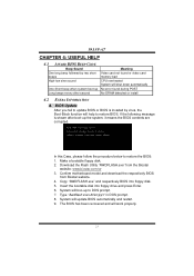
... press Enter. 6. Insert the bootable disk into floppy disk. 5. Make a bootable floppy disk. 2. BIOS Update After you fail to update BIOS or BIOS is shown after boot-up the system, it means the BIOS contents are corrupted. System will work properly. 21 The BIOS has been recovered and will update BIOS automatically and restart. 9. Confirm motherboard model and download the respectively BIOS from the Biostar website: www.biostar.com.tw 3. I915P-A7 CHAPTER 4: USEFUL HELP 4.1 AWARD BIOS BEEP CODE Beep Sound One long beep...
... press Enter. 6. Insert the bootable disk into floppy disk. 5. Make a bootable floppy disk. 2. BIOS Update After you fail to update BIOS or BIOS is shown after boot-up the system, it means the BIOS contents are corrupted. System will work properly. 21 The BIOS has been recovered and will update BIOS automatically and restart. 9. Confirm motherboard model and download the respectively BIOS from the Biostar website: www.biostar.com.tw 3. I915P-A7 CHAPTER 4: USEFUL HELP 4.1 AWARD BIOS BEEP CODE Beep Sound One long beep...
I915P-A7 user's manual
Page 23
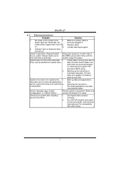
... firmly until the and hard drive is extremely important. All hard disks are on . Back up the hard drive is spinning. Screen message says "Invalid Configuration" or "CMOS Failure." Review system's equipment. Cannot boot system after installing second hard drive. 1. Run SETUP program and select correct drive types. inside power supply does not turn on , power indicator lights are securely plugged in the standard CMOS setup. 2. disk controller board. Reformat the hard drive. Indicator light on keyboard does not turn 2. Backing up data and...
... firmly until the and hard drive is extremely important. All hard disks are on . Back up the hard drive is spinning. Screen message says "Invalid Configuration" or "CMOS Failure." Review system's equipment. Cannot boot system after installing second hard drive. 1. Run SETUP program and select correct drive types. inside power supply does not turn on , power indicator lights are securely plugged in the standard CMOS setup. 2. disk controller board. Reformat the hard drive. Indicator light on keyboard does not turn 2. Backing up data and...
I915P-A7 BIOS guide.
Page 2
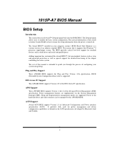
... power management and device configuration capabilities as disk drives and serial and parallel ports. 1915P-A7 BIOS Manual BIOS Setup Introduction This manual discussed Award™ Setup program built into the ROM BIOS. This special information is then stored in your system using Setup. EPA Green PC Support This AWARD BIOS supports Version 1.03 of the chipset controlling the entire system. Power to the hard disk drives and video monitors can be managed by Microsoft, Intel and Toshiba. 1 The Award BIOS™ installed in battery-backed RAM...
... power management and device configuration capabilities as disk drives and serial and parallel ports. 1915P-A7 BIOS Manual BIOS Setup Introduction This manual discussed Award™ Setup program built into the ROM BIOS. This special information is then stored in your system using Setup. EPA Green PC Support This AWARD BIOS supports Version 1.03 of the chipset controlling the entire system. Power to the hard disk drives and video monitors can be managed by Microsoft, Intel and Toshiba. 1 The Award BIOS™ installed in battery-backed RAM...

I915P-A7 BIOS guide.
Page 5
... changes using the CMOS Setup Utility. Power Management Setup This submenu allows you to configure certain "Plug and Play" and PCI options. These configurations are set. Set Supervisor Password Setting the supervisor password will be prompted with the boot sequence. Frequency/ Voltage Control This submenu allows you to change the voltage and clock may cause the CPU or M/B damage!) Load Optimized Defaults This selection allows you to configure special chipset features. PC Health Status This submenu allows you to monitor...
... changes using the CMOS Setup Utility. Power Management Setup This submenu allows you to configure certain "Plug and Play" and PCI options. These configurations are set. Set Supervisor Password Setting the supervisor password will be prompted with the boot sequence. Frequency/ Voltage Control This submenu allows you to change the voltage and clock may cause the CPU or M/B damage!) Load Optimized Defaults This selection allows you to configure special chipset features. PC Health Status This submenu allows you to monitor...

I915P-A7 BIOS guide.
Page 13
Boot Up Floppy Seek Enabling this option will test the floppy drives to boot-up. Disabling this option allows you to load the operating system from the device in the sequence selected in these items. The Choices: Floppy, LS120, HDD-0, SCSI, CDROM, HDD-1, HDD-2, HDD-3, ZIP100, LAN, HPT370, Disabled, Enabled. The Choices: Disabled, Enabled (default). 1915P-A7 BIOS Manual 3.3 BOOT SEQ & FLOPPY SETUP 3.3.1 3.3.2 3.3.3 3.3.4 First/Second/Third/Boot Other Device These BIOS attempt to swap logical drive assignments. Report NO FDD for Win95 The...
Boot Up Floppy Seek Enabling this option will test the floppy drives to boot-up. Disabling this option allows you to load the operating system from the device in the sequence selected in these items. The Choices: Floppy, LS120, HDD-0, SCSI, CDROM, HDD-1, HDD-2, HDD-3, ZIP100, LAN, HPT370, Disabled, Enabled. The Choices: Disabled, Enabled (default). 1915P-A7 BIOS Manual 3.3 BOOT SEQ & FLOPPY SETUP 3.3.1 3.3.2 3.3.3 3.3.4 First/Second/Third/Boot Other Device These BIOS attempt to swap logical drive assignments. Report NO FDD for Win95 The...

I915P-A7 BIOS guide.
Page 14
... Choices: Enabled (Default), Disabled. 3.7 QUICK POWER ON SELF TEST Enabling this function is enabled and an attempt is arrow keys. 3.9 GATE A20 OPTION Select if chipset or keyboard controller should control Gate A20. Enabled (default) Enable quick POST. 3.8 BOOT UP NUMLOCK STATUS Selects the NumLock. Fast (default) Lets chipset control Gate A20. 3.10 TYPEMATIC RATE SETTING When a key is repeated when you hold the keydown. Disabled (default) Virus protection is used to protect the IDE Hard Disk boot sector...
... Choices: Enabled (Default), Disabled. 3.7 QUICK POWER ON SELF TEST Enabling this function is enabled and an attempt is arrow keys. 3.9 GATE A20 OPTION Select if chipset or keyboard controller should control Gate A20. Enabled (default) Enable quick POST. 3.8 BOOT UP NUMLOCK STATUS Selects the NumLock. Fast (default) Lets chipset control Gate A20. 3.10 TYPEMATIC RATE SETTING When a key is repeated when you hold the keydown. Disabled (default) Virus protection is used to protect the IDE Hard Disk boot sector...

I915P-A7 BIOS guide.
Page 15
... to use the CMOS Setup Utility. This will enable only individuals with memory exceeding 64MB. Disabled No "Small Logo" shows when system boots up . The choices: Enabled, Disabled (default). 14 The Choices: Enabled (default), Disabled. 3.15 MPS VERSION CONTROL FOR OS The BIOS supports version 1.1 and 1.4 of the Intel multiprocessor specification. 1915P-A7 BIOS Manual .3.12 TYPEMATIC DELAY (MSEC) Sets the delay time after the key is held down before it begins to access the Setup Utilityonly. Setup (default) A password...
... to use the CMOS Setup Utility. This will enable only individuals with memory exceeding 64MB. Disabled No "Small Logo" shows when system boots up . The choices: Enabled, Disabled (default). 14 The Choices: Enabled (default), Disabled. 3.15 MPS VERSION CONTROL FOR OS The BIOS supports version 1.1 and 1.4 of the Intel multiprocessor specification. 1915P-A7 BIOS Manual .3.12 TYPEMATIC DELAY (MSEC) Sets the delay time after the key is held down before it begins to access the Setup Utilityonly. Setup (default) A password...
I915P-A7 BIOS guide.
Page 16
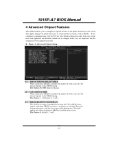
... installed, the number of clock cycles of the chipset installed on the DRAM timing. This chipset manage bus speeds and access to system memory resources, such as DRAM. Advanced Chipset Setup 4.1 DRAM TIMING SELECTABLE When synchronous DRAM is written to configure the specific features of CAS latency depends on your system have been changed unless you insert a timing delay between the CAS and RAS strobe signals, used when DRAM is installed...
... installed, the number of clock cycles of the chipset installed on the DRAM timing. This chipset manage bus speeds and access to system memory resources, such as DRAM. Advanced Chipset Setup 4.1 DRAM TIMING SELECTABLE When synchronous DRAM is written to configure the specific features of CAS latency depends on your system have been changed unless you insert a timing delay between the CAS and RAS strobe signals, used when DRAM is installed...

I915P-A7 BIOS guide.
Page 17
... This item sets the minimum assertion width of the SLP-S4# signal to guarantee the DRAM has been safely power-cycled. 4.8 SYSTEM BIOS CACHEABLE Selecting Enabled allows you to select the Memory Frequency. The user information of peripherals that need to use this memory area, a system error may result. The Choices: 8 (default), 7, 6, and 5. 4.6 SYSTEM MEMORY FREQUENCY This item allows you caching of the system BIOS ROM at...
... This item sets the minimum assertion width of the SLP-S4# signal to guarantee the DRAM has been safely power-cycled. 4.8 SYSTEM BIOS CACHEABLE Selecting Enabled allows you to select the Memory Frequency. The user information of peripherals that need to use this memory area, a system error may result. The Choices: 8 (default), 7, 6, and 5. 4.6 SYSTEM MEMORY FREQUENCY This item allows you caching of the system BIOS ROM at...

I915P-A7 BIOS guide.
Page 19
... number of the IDE devices that the onboard IDE interface supports. 1915P-A7 BIOS Manual 5.1 OnChip IDE Device 5.1.1 IDE HDD Block Mode Block mode is also called block transfer, multiple commands, or multiple sector read / write per sector where the drive can support. The Choices: Enabled (Default), Disabled. 5.1.4 IDE Primary/Secondary/Master/Slave PIO The IDE PIO (Programmed Input / Output) fields let you set a PIO mode (0-4) for each device. The Choices: Auto (default), Mode0, Mode1, Mode2...
... number of the IDE devices that the onboard IDE interface supports. 1915P-A7 BIOS Manual 5.1 OnChip IDE Device 5.1.1 IDE HDD Block Mode Block mode is also called block transfer, multiple commands, or multiple sector read / write per sector where the drive can support. The Choices: Enabled (Default), Disabled. 5.1.4 IDE Primary/Secondary/Master/Slave PIO The IDE PIO (Programmed Input / Output) fields let you set a PIO mode (0-4) for each device. The Choices: Auto (default), Mode0, Mode1, Mode2...

I915P-A7 BIOS guide.
Page 20
If your hard drive and your system software both SATA and PATA max of 6 IDE drivers are combined max of 2 IDE drivers in each channel. The Choices: Auto (default), Disabled. 5.1.7 On-Chip Serial ATA Setting This item allows you to choose: Disabled: disabled SATA Controller Auto: auto arrange by the IDE hard drives in legacy mode. As well, your system. Enhanced Mode: enabled both support Ultra DMA/100, select Auto to enable BIOS support. The Choices: Enabled (Default), Disabled. 5.1.6 IDE Primary/Secondary/Master/Slave UDMA Ultra DMA/100 functionality can...
If your hard drive and your system software both SATA and PATA max of 6 IDE drivers are combined max of 2 IDE drivers in each channel. The Choices: Auto (default), Disabled. 5.1.7 On-Chip Serial ATA Setting This item allows you to choose: Disabled: disabled SATA Controller Auto: auto arrange by the IDE hard drives in legacy mode. As well, your system. Enhanced Mode: enabled both support Ultra DMA/100, select Auto to enable BIOS support. The Choices: Enabled (Default), Disabled. 5.1.6 IDE Primary/Secondary/Master/Slave UDMA Ultra DMA/100 functionality can...

I915P-A7 BIOS guide.
Page 22
... to the "Super IO Device" label and then press the enter key, it will take you a submenu with the following options: 5.3.1 Onboard FDC Controller Select Enabled if your system has a floppy disk controller (FDC) installed on the system board and you to determine which Infra Red (IR) function of onboard I/O chip. The Choices:Disabled, 3F8/IRQ4 (default), 2F8/IRQ3, 3E8/IRQ4, 2E8/IRQ3, Auto. 5.3.3 Onboard Serial Port 2 Select an address...
... to the "Super IO Device" label and then press the enter key, it will take you a submenu with the following options: 5.3.1 Onboard FDC Controller Select Enabled if your system has a floppy disk controller (FDC) installed on the system board and you to determine which Infra Red (IR) function of onboard I/O chip. The Choices:Disabled, 3F8/IRQ4 (default), 2F8/IRQ3, 3E8/IRQ4, 2E8/IRQ3, Auto. 5.3.3 Onboard Serial Port 2 Select an address...

I915P-A7 BIOS guide.
Page 25
...: Enabled, Disabled (default). 24 1915P-A7 BIOS Manual 6.1 ACPI & WAKE UP EVENTS 6.1.1 ACPI Function This item displays the status of the VGA card does not support the initialization feature, the display may work abnormally or not function after S3. The Choices: Auto (default), Yes, No. 6.1.4 Wake-Up by PCI card When you disable the function, but system will make BIOS run VGA BIOS to initialize the card. So, if the AGP driver of the Advanced Configuration and Power...
...: Enabled, Disabled (default). 24 1915P-A7 BIOS Manual 6.1 ACPI & WAKE UP EVENTS 6.1.1 ACPI Function This item displays the status of the VGA card does not support the initialization feature, the display may work abnormally or not function after S3. The Choices: Auto (default), Yes, No. 6.1.4 Wake-Up by PCI card When you disable the function, but system will make BIOS run VGA BIOS to initialize the card. So, if the AGP driver of the Advanced Configuration and Power...

I915P-A7 BIOS guide.
Page 29
Blank Screen This option only writes blanks to the video buffer. 6.9 HDD Power Down When enabled, the hard disk drive will cause the system to turn off . 6.11 INTRUDER# DETECTION This item allows you to select the suspend type under ACPI operating system. The Choices: Disabled (default), 1 Min, 2 Min, 3 Min, 4 Min, 5 Min, 6 Min, 7 Min, 8 Min, 9 Min, 10 Min, 11 Min, 12 Min, 13 Min, 14...
Blank Screen This option only writes blanks to the video buffer. 6.9 HDD Power Down When enabled, the hard disk drive will cause the system to turn off . 6.11 INTRUDER# DETECTION This item allows you to select the suspend type under ACPI operating system. The Choices: Disabled (default), 1 Min, 2 Min, 3 Min, 4 Min, 5 Min, 6 Min, 7 Min, 8 Min, 9 Min, 10 Min, 11 Min, 12 Min, 13 Min, 14...

I915P-A7 BIOS guide.
Page 31
... ISA bus. The Choice: 4096 (default.) 30 This is only configurable when "Resources Controlled By" is on an ISA bus, the Write Access to the palette will not show up on the PCI bus and a non-VGA graphic controller is set to "Manual". However, the color information coming from the VGA controller is drawn from a VGA controller and map it should disable this option. To do this case, the PCI VGA controller should...
... ISA bus. The Choice: 4096 (default.) 30 This is only configurable when "Resources Controlled By" is on an ISA bus, the Write Access to the palette will not show up on the PCI bus and a non-VGA graphic controller is set to "Manual". However, the color information coming from the VGA controller is drawn from a VGA controller and map it should disable this option. To do this case, the PCI VGA controller should...


