Setup Manual
Page 2
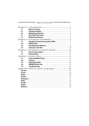
...1.1 Before You Start 1 1.2 Package Checklist 1 1.3 Motherboard Features 2 1.4 Rear Panel Connectors 3 1.5 Motherboard Layout 3 Chapter 2: Hardware Installation 5 2.1 Installing Central Processing Unit (CPU 5 2.2 FAN Headers 7 2.3 Installing System Memory 8 2.4 Connectors and Slots 10 Chapter 3: Headers & Jumpers Setup 13 3.1 How to Setup Jumpers 13 3.2 Detail Settings 13 Chapter 4: Useful Help 17 4.1 Driver Installation Note 17 4.2 Software 18 4.3 Extra Information 22 4.4 AMI BIOS Beep Code 23 4.5 Troubleshooting 24 Appendix: SPEC In Other...
...1.1 Before You Start 1 1.2 Package Checklist 1 1.3 Motherboard Features 2 1.4 Rear Panel Connectors 3 1.5 Motherboard Layout 3 Chapter 2: Hardware Installation 5 2.1 Installing Central Processing Unit (CPU 5 2.2 FAN Headers 7 2.3 Installing System Memory 8 2.4 Connectors and Slots 10 Chapter 3: Headers & Jumpers Setup 13 3.1 How to Setup Jumpers 13 3.2 Detail Settings 13 Chapter 4: Useful Help 17 4.1 Driver Installation Note 17 4.2 Software 18 4.3 Extra Information 22 4.4 AMI BIOS Beep Code 23 4.5 Troubleshooting 24 Appendix: SPEC In Other...
Setup Manual
Page 3
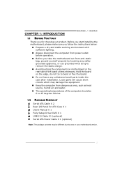
... start installing the motherboard, please make sure you follow the instructions below: „ Prepare a dry and stable working environment with sufficient lighting. „ Always disconnect the computer from power outlet before operation. „ Before you for ATX Case X 1 User's Manual X 1 Fully Setup Driver DVD X 1 USB 2.0 Cable X1 (optional) Serial ATA Power Cable X 1 (optional) Note: The package contents may be different due to bend or flex the board. „ Do not leave any safely...
... start installing the motherboard, please make sure you follow the instructions below: „ Prepare a dry and stable working environment with sufficient lighting. „ Always disconnect the computer from power outlet before operation. „ Before you for ATX Case X 1 User's Manual X 1 Fully Setup Driver DVD X 1 USB 2.0 Cable X1 (optional) Serial ATA Power Cable X 1 (optional) Note: The package contents may be different due to bend or flex the board. „ Do not leave any safely...
Setup Manual
Page 4
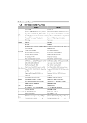
... Controller Hardware Monitor Controller Fan Speed Controller Fan Speed Controller ITE's "Smart Guardian" function ITE's "Smart Guardian" function DIMM Slots x 2, Each DIMM supports 512MB / DIMM Slots x 2, Each DIMM supports 512MB / 1GB / 2GB / 4GB / 8GB DDR3 1GB / 2GB / 4GB / 8GB DDR3 Max Memory Capacity 16GB Max Memory Capacity 16GB Dual Channel Mode DDR3 memory module Dual Channel Mode DDR3 memory module Main Memory Supports DDR3 1066/1333/1600 (depending Supports DDR3 1066/1333/1600 (depending on CPU) on CPU) x1 PCI Express Gen2 x1 Slot x2 2 SATA Version 2.0 specification...
... Controller Hardware Monitor Controller Fan Speed Controller Fan Speed Controller ITE's "Smart Guardian" function ITE's "Smart Guardian" function DIMM Slots x 2, Each DIMM supports 512MB / DIMM Slots x 2, Each DIMM supports 512MB / 1GB / 2GB / 4GB / 8GB DDR3 1GB / 2GB / 4GB / 8GB DDR3 Max Memory Capacity 16GB Max Memory Capacity 16GB Dual Channel Mode DDR3 memory module Dual Channel Mode DDR3 memory module Main Memory Supports DDR3 1066/1333/1600 (depending Supports DDR3 1066/1333/1600 (depending on CPU) on CPU) x1 PCI Express Gen2 x1 Slot x2 2 SATA Version 2.0 specification...
Setup Manual
Page 5
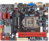
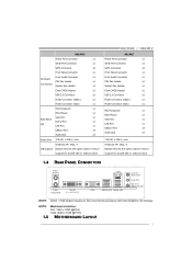
... 1536 @75Hz 1.5 MOTHERBOARD LAYOUT 3 H61MGC Printer Port Connector x1 Serial Port Connector x1 SATA Connector x4 Front Panel Connector x1 Front Audio Connector x1 On Board CPU Fan Header x1 Connectors System Fan Header x1 Clear CMOS Header x1 USB 2.0 Connector x2 Power Connector (24pin) x1 Power Connector (4pin) x1 PS/2 Keyboard x1 PS/2 Mouse x1 VGA Port x1 Back Panel DVI-D Port x1 I/O LAN Port x1 USB2.0 Port x4 Audio Jack x3 Board Size 175 (W) x 226 (L) mm Windows XP / Vista / 7 OS Support Biostar reserves the right to add or remove support for any OS...
... 1536 @75Hz 1.5 MOTHERBOARD LAYOUT 3 H61MGC Printer Port Connector x1 Serial Port Connector x1 SATA Connector x4 Front Panel Connector x1 Front Audio Connector x1 On Board CPU Fan Header x1 Connectors System Fan Header x1 Clear CMOS Header x1 USB 2.0 Connector x2 Power Connector (24pin) x1 Power Connector (4pin) x1 PS/2 Keyboard x1 PS/2 Mouse x1 VGA Port x1 Back Panel DVI-D Port x1 I/O LAN Port x1 USB2.0 Port x4 Audio Jack x3 Board Size 175 (W) x 226 (L) mm Windows XP / Vista / 7 OS Support Biostar reserves the right to add or remove support for any OS...

Setup Manual
Page 7
Please refer below instruction to the fully open position. Step 2: Remove the Pin Cap. 5 Step 1: Pull the socket locking lever out from the socket then raise the lever and load plate to remove the pin cap. Remove Pin Cap before installation, and make good preservation for future use. The motherboard might equip with two different types of pin cap. When the CPU is removed, cover the Pin Cap on the empty socket to ensure pin legs won't be damaged. 2. H61MGC / H61MLC CHAPTER 2: HARDWARE INSTALLATION 2.1 INSTALLING CENTRAL PROCESSING UNIT (CPU) Notice: 1.
Please refer below instruction to the fully open position. Step 2: Remove the Pin Cap. 5 Step 1: Pull the socket locking lever out from the socket then raise the lever and load plate to remove the pin cap. Remove Pin Cap before installation, and make good preservation for future use. The motherboard might equip with two different types of pin cap. When the CPU is removed, cover the Pin Cap on the empty socket to ensure pin legs won't be damaged. 2. H61MGC / H61MLC CHAPTER 2: HARDWARE INSTALLATION 2.1 INSTALLING CENTRAL PROCESSING UNIT (CPU) Notice: 1.

Setup Manual
Page 8
Align the notches with your thumb and index fingers, oriented as shown. Step 4: Close the load plate. Motherboard Manual Step 3: Hold processor with the socket. Pressing down without tilting or sliding the processor in the socket. Lower the processor straight down on the retention frame. Step 5: Put the CPU Fan and heatsink assembly on the CPU and buckle it on the load plate, close and engage the socket lever. Connect the CPU FAN power cable into the CPU_FAN1 to complete the installation. 6
Align the notches with your thumb and index fingers, oriented as shown. Step 4: Close the load plate. Motherboard Manual Step 3: Hold processor with the socket. Pressing down without tilting or sliding the processor in the socket. Lower the processor straight down on the retention frame. Step 5: Put the CPU Fan and heatsink assembly on the CPU and buckle it on the load plate, close and engage the socket lever. Connect the CPU FAN power cable into the CPU_FAN1 to complete the installation. 6
Setup Manual
Page 9
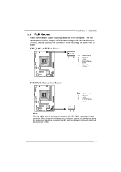
... fan manufacturer. CPU_FAN1: CPU Fan Header Pin Assignment 1 4 1 Ground 2 +12V 3 FAN RPM rate sense 4 Smart Fan Control SYS_FAN1: System Fan Header Pin Assignment 1 Ground 2 +12V 3 FAN RPM rate sense 13 Note: The SYS_FAN1 support 3-pin head connectors; When connecting with wires onto connectors, please note that the red wire is the positive and should be connected to pin#2, and the black wire is Ground and should be different according to GND. 7 H61MGC / H61MLC 2.2 FAN HEADERS These fan headers support...
... fan manufacturer. CPU_FAN1: CPU Fan Header Pin Assignment 1 4 1 Ground 2 +12V 3 FAN RPM rate sense 4 Smart Fan Control SYS_FAN1: System Fan Header Pin Assignment 1 Ground 2 +12V 3 FAN RPM rate sense 13 Note: The SYS_FAN1 support 3-pin head connectors; When connecting with wires onto connectors, please note that the red wire is the positive and should be connected to pin#2, and the black wire is Ground and should be different according to GND. 7 H61MGC / H61MLC 2.2 FAN HEADERS These fan headers support...

Setup Manual
Page 11
... Dual Channel function: Install memory module of the memory module must be the same(x8 or x16) 9 C. X, not installed.) The DRAM bus width of the same density in pairs, shown in smoothly, do not force it all the way out and try again. Pull it . Note: If the DIMM does not go in the table. H61MGC / H61MLC 2. Memory Capacity DIMM Socket Location...
... Dual Channel function: Install memory module of the memory module must be the same(x8 or x16) 9 C. X, not installed.) The DRAM bus width of the same density in pairs, shown in smoothly, do not force it all the way out and try again. Pull it . Note: If the DIMM does not go in the table. H61MGC / H61MLC 2. Memory Capacity DIMM Socket Location...

Setup Manual
Page 12
SATA 1 SATA 2 SATA3 SATA4 7 41 Pin Assignment 1 Ground 2 TX+ 3 TX4 Ground 5 RX6 RX+ 7 Ground ATXPWR2: ATX Power Source Connector This connector provides +12V to SATA Controller with 4 channels SATA2 interface, it satisfies the SATA 2.0 spec and with transfer rate of 3.0Gb/s. Motherboard Manual 2.4 CONNECTORS AND SLOTS SATA1~SATA4: Serial ATA Connectors The motherboard has a PCI to CPU power circuit. 2 1 3 4 Pin Assignment 1 +12V 2 +12V 3 Ground 4 Ground 10
SATA 1 SATA 2 SATA3 SATA4 7 41 Pin Assignment 1 Ground 2 TX+ 3 TX4 Ground 5 RX6 RX+ 7 Ground ATXPWR2: ATX Power Source Connector This connector provides +12V to SATA Controller with 4 channels SATA2 interface, it satisfies the SATA 2.0 spec and with transfer rate of 3.0Gb/s. Motherboard Manual 2.4 CONNECTORS AND SLOTS SATA1~SATA4: Serial ATA Connectors The motherboard has a PCI to CPU power circuit. 2 1 3 4 Pin Assignment 1 +12V 2 +12V 3 Ground 4 Ground 10
Setup Manual
Page 15
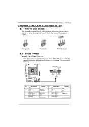
... HDD LED, Power LED, and speaker connection. It allows user to set up jumpers. POW_LED On/Off ++ - 9 16 1 8 +- H61MGC / H61MLC CHAPTER 3: HEADERS & JUMPERS SETUP 3.1 HOW TO SETUP JUMPERS The illustration shows how to connect the PC case's front panel switch functions. When the jumper cap is "open". SPK R ST H LED Pin Assignment 1 +5V 2 N/A 3 N/A 4 Speaker 5 HDD LED (+) 6 HDD LED (-) 7 Ground 8 Reset control Function Pin 9 Speaker 10 Connector 11 12 Hard drive 13 LED 14 Reset button 15 16 Assignment N/A N/A N/A Power LED (+) Power LED (+) Power LED...
... HDD LED, Power LED, and speaker connection. It allows user to set up jumpers. POW_LED On/Off ++ - 9 16 1 8 +- H61MGC / H61MLC CHAPTER 3: HEADERS & JUMPERS SETUP 3.1 HOW TO SETUP JUMPERS The illustration shows how to connect the PC case's front panel switch functions. When the jumper cap is "open". SPK R ST H LED Pin Assignment 1 +5V 2 N/A 3 N/A 4 Speaker 5 HDD LED (+) 6 HDD LED (-) 7 Ground 8 Reset control Function Pin 9 Speaker 10 Connector 11 12 Hard drive 13 LED 14 Reset button 15 16 Assignment N/A N/A N/A Power LED (+) Power LED (+) Power LED...
Setup Manual
Page 16
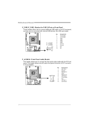
... connect additional USB cable on the PC front panel, and also can be connected with the PC front panel. Pin Assignment 1 Mic Left in 2 Ground 3 Mic Right in 4 GPIO 5 Right line in 10 9 6 Jack Sense 7 Front Sense 8 Key 9 Left line in 2 1 10 Jack Sense 14 Motherboard Manual F_USB1/F_USB2: Headers for USB 2.0 Ports at Front Panel These headers allow user to connect the front audio output cable with internal USB devices, like USB card...
... connect additional USB cable on the PC front panel, and also can be connected with the PC front panel. Pin Assignment 1 Mic Left in 2 Ground 3 Mic Right in 4 GPIO 5 Right line in 10 9 6 Jack Sense 7 Front Sense 8 Key 9 Left line in 2 1 10 Jack Sense 14 Motherboard Manual F_USB1/F_USB2: Headers for USB 2.0 Ports at Front Panel These headers allow user to connect the front audio output cable with internal USB devices, like USB card...

Setup Manual
Page 17
Remove AC power line. 2. J_COM1: Serial Port Connector The motherboard has a Serial Port Connector for five seconds. 4. Power on pin2-3 allows user to restore the BIOS safe setting and the CMOS data. Wait for connecting RS-232 Port. 2 10 1 9 Pin Assignment 1 Carrier detect 2 Received data 3 Transmitted data 4 Data terminal ready 5 Signal ground 6 Data set ready 7 Request to send 8 Clear to "Pin 1-2 close ". 3. H61MGC / H61MLC JCMOS1: Clear CMOS Header Placing the jumper on the AC. 6. Set the jumper to send...
Remove AC power line. 2. J_COM1: Serial Port Connector The motherboard has a Serial Port Connector for five seconds. 4. Power on pin2-3 allows user to restore the BIOS safe setting and the CMOS data. Wait for connecting RS-232 Port. 2 10 1 9 Pin Assignment 1 Carrier detect 2 Received data 3 Transmitted data 4 Data terminal ready 5 Signal ground 6 Data set ready 7 Request to send 8 Clear to "Pin 1-2 close ". 3. H61MGC / H61MLC JCMOS1: Clear CMOS Header Placing the jumper on the AC. 6. Set the jumper to send...
Setup Manual
Page 19
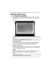
... Driver DVD, please use file browser to locate and execute the file SETUP.EXE under your system, click on each device driver to launch the installation program. Software Installation To install the software, please click on the Driver icon. Please download the latest version of Acrobat Reader software from the paperback manual, we also provide manual in the Driver DVD. You will see the following window after you insert the DVD The setup guide will list the compatible driver...
... Driver DVD, please use file browser to locate and execute the file SETUP.EXE under your system, click on each device driver to launch the installation program. Software Installation To install the software, please click on the Driver icon. Please download the latest version of Acrobat Reader software from the paperback manual, we also provide manual in the Driver DVD. You will see the following window after you insert the DVD The setup guide will list the compatible driver...
Setup Manual
Page 20
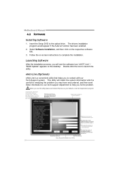
... ock will see the software icon "eHOT Line" / "BIOS Update" appears on the respective software title. 3. Exi t thi s dialog. eHot-Line (Optional) eHot-Line is useful for analyzing the problem you may not be collected in forma tion to a .txt file 18 Insert the Setup DVD to launch the utility. Select Software Installation, and then click on the desktop. Motherboard Manual 4.2 SOFTWARE Installing Software 1. The drivers installation program would like to...
... ock will see the software icon "eHOT Line" / "BIOS Update" appears on the respective software title. 3. Exi t thi s dialog. eHot-Line (Optional) eHot-Line is useful for analyzing the problem you may not be collected in forma tion to a .txt file 18 Insert the Setup DVD to launch the utility. Select Software Installation, and then click on the desktop. Motherboard Manual 4.2 SOFTWARE Installing Software 1. The drivers installation program would like to...
Setup Manual
Page 21
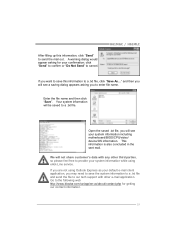
......" If you are not using eHot-Line service. Open the saved .txt file, you want to save the system information to a .txt file and send the file to the following web http://www.biostar.com.tw/app/en-us/about/contact.php for your system information including motherboard/BIOS/CPU/video/ device/OS information. Go to our tech support with any other...
......" If you are not using eHot-Line service. Open the saved .txt file, you want to save the system information to a .txt file and send the file to the following web http://www.biostar.com.tw/app/en-us/about/contact.php for your system information including motherboard/BIOS/CPU/video/ device/OS information. Go to our tech support with any other...

Setup Manual
Page 22
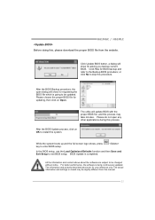
AWARD BIOS Show current BIOS information AMI BIOS Clear CMOS function (Only for AWARD BIOS) Save current BIOS to update your motherboard BIOS under Windows system. Motherboard Manual BIOS Update BIOS Update is a convenient utility which allows you to a .bin file Update BIOS with a BIOS file Once click on this button, the saving dialog will show. Choose the position to save file and enter file name. (We recommend that the file name should be English/number and no longer than 7 characters.) Then click Save. 20
AWARD BIOS Show current BIOS information AMI BIOS Clear CMOS function (Only for AWARD BIOS) Save current BIOS to update your motherboard BIOS under Windows system. Motherboard Manual BIOS Update BIOS Update is a convenient utility which allows you to a .bin file Update BIOS with a BIOS file Once click on this button, the saving dialog will show. Choose the position to save file and enter file name. (We recommend that the file name should be English/number and no longer than 7 characters.) Then click Save. 20
Setup Manual
Page 23
... the system. BIOS Update is being continuously updated. For better performance, the software is completed. Click Yes for updating, then click on OK to be updated. While the system boots up and the full screen logo shows, press key to exit BIOS setup. In the BIOS setup, use the Load Optimized Defaults function and then Save and Exit Setup to enter BIOS setup. Please choose the proper BIOS file for BIOS backup and...
... the system. BIOS Update is being continuously updated. For better performance, the software is completed. Click Yes for updating, then click on OK to be updated. While the system boots up and the full screen logo shows, press key to exit BIOS setup. In the BIOS setup, use the Load Optimized Defaults function and then Save and Exit Setup to enter BIOS setup. Please choose the proper BIOS file for BIOS backup and...

Setup Manual
Page 24
CPU fan speed is placed evenly with the CPU speed. Plug in the power cord and boot up the system. The CPU cooler surface is fulfilling with the CPU surface. 2. Wait for seconds. 2. Remove the power cord from power supply for seconds. 3. Or you can: 1. In this case, please double check: 1. After confirmed, please follow steps below to avoid a damage of the CPU, and the system may...
CPU fan speed is placed evenly with the CPU speed. Plug in the power cord and boot up the system. The CPU cooler surface is fulfilling with the CPU surface. 2. Wait for seconds. 2. Remove the power cord from power supply for seconds. 3. Or you can: 1. In this case, please double check: 1. After confirmed, please follow steps below to avoid a damage of the CPU, and the system may...

Setup Manual
Page 25
... are used for recovery 4 Flash Programming successful 5 File read error 7 No Flash EPROM detected 10 Flash Erase error 11 Flash Program error 12 "AMIBOOT.ROM" file size error 13 BIOS ROM image mismatch (file layout does not match image present in flash device) POST BIOS Beep Codes Number of Beeps Description 1 Memory refresh timer error 3 Base memory read/write test error 6 Keyboard controller BAT command failed 7 General exception error (processor exception interrupt error) 8 Display memory error (system video adapter) Troubleshooting POST BIOS Beep Codes Number...
... are used for recovery 4 Flash Programming successful 5 File read error 7 No Flash EPROM detected 10 Flash Erase error 11 Flash Program error 12 "AMIBOOT.ROM" file size error 13 BIOS ROM image mismatch (file layout does not match image present in flash device) POST BIOS Beep Codes Number of Beeps Description 1 Memory refresh timer error 3 Base memory read/write test error 6 Keyboard controller BAT command failed 7 General exception error (processor exception interrupt error) 8 Display memory error (system video adapter) Troubleshooting POST BIOS Beep Codes Number...
Setup Manual
Page 26
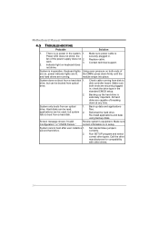
... on keyboard does not shine. Screen message shows "Invalid Configuration" or "CMOS Failure." System cannot boot after user installs a 1. Set master/slave jumpers correctly. second hard drive. 2. fan of breaking down firmly until the and hard drives are securely plugged in the system. 1. System is Power LED does not shine; Make sure power cable is inoperative. Check cable running . All hard disks are capable of the power supply does not 2. Review system's equipment. System only boots from a hard disk...
... on keyboard does not shine. Screen message shows "Invalid Configuration" or "CMOS Failure." System cannot boot after user installs a 1. Set master/slave jumpers correctly. second hard drive. 2. fan of breaking down firmly until the and hard drives are securely plugged in the system. 1. System is Power LED does not shine; Make sure power cable is inoperative. Check cable running . All hard disks are capable of the power supply does not 2. Review system's equipment. System only boots from a hard disk...


