Setup Manual
Page 2
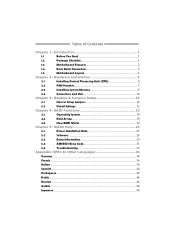
Table of Contents Chapter 1: Introduction 1 1.1 Before You Start 1 1.2 Package Checklist 1 1.3 Motherboard Features 2 1.4 Rear Panel Connectors 3 1.5 Motherboard Layout 4 Chapter 2: Hardware Installation 5 2.1 Installing Central Processing Unit (CPU 5 2.2 FAN Headers 7 2.3 Installing System Memory 8 2.4 Connectors and Slots 10 Chapter 3: Headers & Jumpers Setup 12 3.1 How to ...
Table of Contents Chapter 1: Introduction 1 1.1 Before You Start 1 1.2 Package Checklist 1 1.3 Motherboard Features 2 1.4 Rear Panel Connectors 3 1.5 Motherboard Layout 4 Chapter 2: Hardware Installation 5 2.1 Installing Central Processing Unit (CPU 5 2.2 FAN Headers 7 2.3 Installing System Memory 8 2.4 Connectors and Slots 10 Chapter 3: Headers & Jumpers Setup 12 3.1 How to ...

Setup Manual
Page 3
...M2+ TE/GF8200C M2+ CHAPTER 1: INTRODUCTION 1.1 BEFORE YOU START Thank you take the motherboard out from anti-static bag, ground yourself properly by touching any safely grounded appliance, or use grounded wrist strap to remove the static charge. „ Avoid touching the components on the edge, do not try to area or your motherboard...Fully Setup Driver CD X 1 (full version manual files inside the case after installation. Before you start installing the motherboard, please make sure you follow the instructions below: „ Prepare a dry and stable working environment with sufficient lighting...
...M2+ TE/GF8200C M2+ CHAPTER 1: INTRODUCTION 1.1 BEFORE YOU START Thank you take the motherboard out from anti-static bag, ground yourself properly by touching any safely grounded appliance, or use grounded wrist strap to remove the static charge. „ Avoid touching the components on the edge, do not try to area or your motherboard...Fully Setup Driver CD X 1 (full version manual files inside the case after installation. Before you start installing the motherboard, please make sure you follow the instructions below: „ Prepare a dry and stable working environment with sufficient lighting...
Setup Manual
Page 4
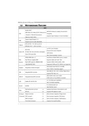
Motherboard Manual 1.3 MOTHERBOARD FEATURES SPEC Socket AM2+ AMD 64 Architecture enables 32 and 64 bit AMD Athlon 64 / Athlon 64 FX / Athlon 64 x2 CPU computing / Sempron / PhenomX3 processors Supports Hyper Transport 3.0 and PowerNow (Maximum Watt: 95W) Support HyperTransport 3.0 FSB Supports up to 5.2 GT/s Bandwidth Chipset GF8100 M2+ TE: GeForce 8100 GF8200C M2+ : GeForce 8200 ITE...
Motherboard Manual 1.3 MOTHERBOARD FEATURES SPEC Socket AM2+ AMD 64 Architecture enables 32 and 64 bit AMD Athlon 64 / Athlon 64 FX / Athlon 64 x2 CPU computing / Sempron / PhenomX3 processors Supports Hyper Transport 3.0 and PowerNow (Maximum Watt: 95W) Support HyperTransport 3.0 FSB Supports up to 5.2 GT/s Bandwidth Chipset GF8100 M2+ TE: GeForce 8100 GF8200C M2+ : GeForce 8200 ITE...
Setup Manual
Page 6
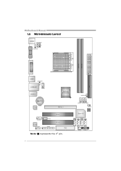
JUSB4 JUSB2 JUSB3 Super I/O JCMOS B IO S SATA1 SATA3 SATA2 SATA4 JS FAN JPANEL1 4 Motherboard Manual 1.5 MOTHERBOARD LAYOUT JKBMS J ATXPW R2 J KB_PW R JATXPWR1 S ocket AM 2+ DVI VG A DIMMA1 DIMMB1 ID E JUSB1 JUS BPWR1 JUSBLAN1 J CFAN JAUDIO1 GeForce 8100/8200 JUSBPWR2 BAT1 LAN PEX16_1 JAU DIOF Codec JCOM J CDIN JPRNT PCI1 PCI2 FDD Note: ■ represents the 1st pin.
JUSB4 JUSB2 JUSB3 Super I/O JCMOS B IO S SATA1 SATA3 SATA2 SATA4 JS FAN JPANEL1 4 Motherboard Manual 1.5 MOTHERBOARD LAYOUT JKBMS J ATXPW R2 J KB_PW R JATXPWR1 S ocket AM 2+ DVI VG A DIMMA1 DIMMB1 ID E JUSB1 JUS BPWR1 JUSBLAN1 J CFAN JAUDIO1 GeForce 8100/8200 JUSBPWR2 BAT1 LAN PEX16_1 JAU DIOF Codec JCOM J CDIN JPRNT PCI1 PCI2 FDD Note: ■ represents the 1st pin.
Setup Manual
Page 8
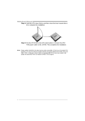
... and buckle it. Connect the CPU FAN power cable to boot your system, and update the latest BIOS from our website for AM2+ CPUs support. 6 Motherboard Manual Step 4: Hold the CPU down firmly, and then close the lever toward direct B to boot while using AM2+ CPUs. Due to the latest CPU...
... and buckle it. Connect the CPU FAN power cable to boot your system, and update the latest BIOS from our website for AM2+ CPUs support. 6 Motherboard Manual Step 4: Hold the CPU down firmly, and then close the lever toward direct B to boot while using AM2+ CPUs. Due to the latest CPU...
Setup Manual
Page 10
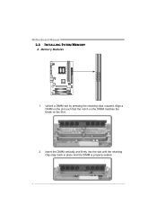
Align a DIMM on the slot such that the notch on the DIMM matches the break on the Slot. 2. Unlock a DIMM slot by pressing the retaining clips outward. Insert the DIMM vertically and firmly into the slot until the retaining chip snap back in place and the DIMM is properly seated. 8 Memory Modules 1. DIMMA1 DIMMB 1 Motherboard Manual 2.3 INSTALLING SYSTEM MEMORY A.
Align a DIMM on the slot such that the notch on the DIMM matches the break on the Slot. 2. Unlock a DIMM slot by pressing the retaining clips outward. Insert the DIMM vertically and firmly into the slot until the retaining chip snap back in place and the DIMM is properly seated. 8 Memory Modules 1. DIMMA1 DIMMB 1 Motherboard Manual 2.3 INSTALLING SYSTEM MEMORY A.
Setup Manual
Page 11
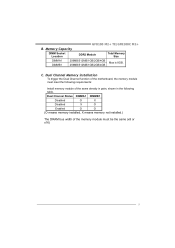
Dual Channel Memory installation To trigger the Dual Channel function of the motherboard, the memory module must meet the following requirements: Install memory module of the memory module must be the same (x8 or x16) 9 Dual Channel Status ... O O (O means memory installed, X means memory not installed.) The DRAM bus width of the same density in pairs, shown in the following table. B. Memory Capacity GF8100 M2+ TE/GF8200C M2+ DIMM Socket Location DDR2 Module Total Memory Size DIMMA1 DIMMB1 256MB/512MB/1GB/2GB/4GB Max is 8GB. 256MB/512MB/1GB/2GB/4GB C.
Dual Channel Memory installation To trigger the Dual Channel function of the motherboard, the memory module must meet the following requirements: Install memory module of the memory module must be the same (x8 or x16) 9 Dual Channel Status ... O O (O means memory installed, X means memory not installed.) The DRAM bus width of the same density in pairs, shown in the following table. B. Memory Capacity GF8100 M2+ TE/GF8200C M2+ DIMM Socket Location DDR2 Module Total Memory Size DIMMA1 DIMMB1 256MB/512MB/1GB/2GB/4GB Max is 8GB. 256MB/512MB/1GB/2GB/4GB C.
Setup Manual
Page 12
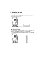
Motherboard Manual 2.4 CONNECTORS AND SLOTS FDD: Floppy Disk Connector The motherboard provides a standard floppy disk connector that provides PIO Mode 0~4, Bus Master, and Ultra DMA 33/66/100/133 functionality. This connector supports the provided floppy drive ribbon cable. 2 34 1 33 IDE: IDE/ATAPI Connector The motherboard has a 32-bit Enhanced PCI IDE Controller that supports 360K, 720K, 1.2M, 1.44M and 2.88M floppy disk types. The IDE connector can connect a master and a slave drive, so you can connect up to two drives. 40 39 21 10
Motherboard Manual 2.4 CONNECTORS AND SLOTS FDD: Floppy Disk Connector The motherboard provides a standard floppy disk connector that provides PIO Mode 0~4, Bus Master, and Ultra DMA 33/66/100/133 functionality. This connector supports the provided floppy drive ribbon cable. 2 34 1 33 IDE: IDE/ATAPI Connector The motherboard has a 32-bit Enhanced PCI IDE Controller that supports 360K, 720K, 1.2M, 1.44M and 2.88M floppy disk types. The IDE connector can connect a master and a slave drive, so you can connect up to two drives. 40 39 21 10
Setup Manual
Page 13
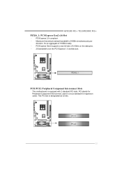
... 32 bits. PCI-Express Gen2 supports a raw bit-rate of 16GB/s totally. - PCI stands for expansion cards. PEX16_1 PCI1/PCI2: Peripheral Component Interconnect Slots This motherboard is equipped with 2 standard PCI slots. PCI-Express 2.0 compliant. - PCI1 PCI2 11 GF8100 M2+ TE/GF8200C M2+ PEX16_1: PCI-Express Gen2 x16 Slot -
... 32 bits. PCI-Express Gen2 supports a raw bit-rate of 16GB/s totally. - PCI stands for expansion cards. PEX16_1 PCI1/PCI2: Peripheral Component Interconnect Slots This motherboard is equipped with 2 standard PCI slots. PCI-Express 2.0 compliant. - PCI1 PCI2 11 GF8100 M2+ TE/GF8200C M2+ PEX16_1: PCI-Express Gen2 x16 Slot -
Setup Manual
Page 14
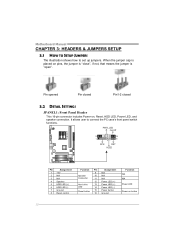
... user to set up jumpers. When the jumper cap is placed on pins, the jumper is "close", if not, that means the jumper is "open". Motherboard Manual CHAPTER 3: HEADERS & JUMPERS SETUP 3.1 HOW TO SETUP JUMPERS The illustration shows how to connect the PC case's front panel switch functions.
... user to set up jumpers. When the jumper cap is placed on pins, the jumper is "close", if not, that means the jumper is "open". Motherboard Manual CHAPTER 3: HEADERS & JUMPERS SETUP 3.1 HOW TO SETUP JUMPERS The illustration shows how to connect the PC case's front panel switch functions.
Setup Manual
Page 16
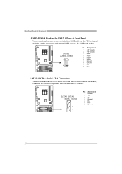
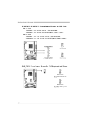
... a PCI to connect additional USB cable on the PC front panel, and also can be connected with transfer rate of 3.0Gb/s. Motherboard Manual JUSB2~JUSB4: Headers for USB 2.0 Ports at Front Panel These headers allow user to SATA Controller with 4 channels SATA interface, it satisfies the SATA 2.0 ...
... a PCI to connect additional USB cable on the PC front panel, and also can be connected with transfer rate of 3.0Gb/s. Motherboard Manual JUSB2~JUSB4: Headers for USB 2.0 Ports at Front Panel These headers allow user to SATA Controller with 4 channels SATA interface, it satisfies the SATA 2.0 ...
Setup Manual
Page 18
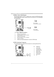
...carefully follow the procedures to "Pin 1-2 close ". 3. JCOM: Serial port Connector The motherboard has a Serial Port Connector for five seconds. 4. Set the jumper to send 9 Ring indicator 10 NC 16 Motherboard Manual JCMOS: Clear CMOS Header By placing the jumper on the AC. 6. Reset your... desired password or clear the CMOS data. Remove AC power line. 2. Set the jumper to avoid damaging the motherboard. 31 Pin 1-2 Close: Normal Operation...
...carefully follow the procedures to "Pin 1-2 close ". 3. JCOM: Serial port Connector The motherboard has a Serial Port Connector for five seconds. 4. Set the jumper to send 9 Ring indicator 10 NC 16 Motherboard Manual JCMOS: Clear CMOS Header By placing the jumper on the AC. 6. Reset your... desired password or clear the CMOS data. Remove AC power line. 2. Set the jumper to avoid damaging the motherboard. 31 Pin 1-2 Close: Normal Operation...
Setup Manual
Page 20
JUSBPWR1 1 3 3 1 JUSBPWR2 1 3 Pin 1-2 close 1 3 Pin 2-3 close JKB_PWR: Power Source Header for PS/2 Keyboard and Mouse 3 3 1 1 Pin 1-2 close +5V for PS/2 keyboard and mouse. 3 1 Pin 2-3 close +5V STB for USB ports at front panel (JUSB2~JUSB4). Pin 2-3 Close: JUSBPWR1: +5V STB for USB ports at JUSB1/JUSBLAN1. Motherboard Manual JUSBPWR1/JUSBPWR2: Power Source Headers for USB Ports Pin 1-2 Close: JUSBPWR1: +5V for USB ports at JUSB1/JUSBLAN1. JUSBPWR2: +5V for USB ports at front panel (JUSB2~JUSB4). JUSBPWR2: +5V STB for PS/2 keyboard and mouse. 18
JUSBPWR1 1 3 3 1 JUSBPWR2 1 3 Pin 1-2 close 1 3 Pin 2-3 close JKB_PWR: Power Source Header for PS/2 Keyboard and Mouse 3 3 1 1 Pin 1-2 close +5V for PS/2 keyboard and mouse. 3 1 Pin 2-3 close +5V STB for USB ports at front panel (JUSB2~JUSB4). Pin 2-3 Close: JUSBPWR1: +5V STB for USB ports at JUSB1/JUSBLAN1. Motherboard Manual JUSBPWR1/JUSBPWR2: Power Source Headers for USB Ports Pin 1-2 Close: JUSBPWR1: +5V for USB ports at JUSB1/JUSBLAN1. JUSBPWR2: +5V for USB ports at front panel (JUSB2~JUSB4). JUSBPWR2: +5V STB for PS/2 keyboard and mouse. 18
Setup Manual
Page 22
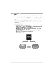
...-availability solutions, or as a form of one drive fail, the controller switches to more expensive and less reliable media. Fault Tolerance: Yes. Should one drive. Motherboard Manual RAID 1: Every read and write is actually carried out in parallel across 2 disk drives in the array.
...-availability solutions, or as a form of one drive fail, the controller switches to more expensive and less reliable media. Fault Tolerance: Yes. Should one drive. Motherboard Manual RAID 1: Every read and write is actually carried out in parallel across 2 disk drives in the array.
Setup Manual
Page 24
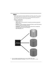
... G eF o rc e 8100/8200 Disk 2 DATA 2 PARITY DATA 5 DATA 8 PARITY DATA 11 Disk 3 PARITY DATA 4 DATA 6 PARITY DATA 10 DATA 12 ※ For more drives. Motherboard Manual RAID 5: RAID 5 stripes both data and parity information across all the drives in the array.
... G eF o rc e 8100/8200 Disk 2 DATA 2 PARITY DATA 5 DATA 8 PARITY DATA 11 Disk 3 PARITY DATA 4 DATA 6 PARITY DATA 10 DATA 12 ※ For more drives. Motherboard Manual RAID 5: RAID 5 stripes both data and parity information across all the drives in the array.
Setup Manual
Page 25
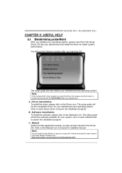
... Click on the Manual icon to open the manual file. GF8100 M2+ TE/GF8200C M2+ CHAPTER 5: USEFUL HELP 5.1 DRIVER INSTALLATION NOTE After you installed your operating system, please insert the Fully Setup Driver CD into your motherboard and operating system. Click on each device driver to launch the...setup guide will list the compatible driver for your optical drive. The setup guide will list the software available for your motherboard and operating system. Please download the latest version of Acrobat Reader software from the paperback manual, we also provide manual in ...
... Click on the Manual icon to open the manual file. GF8100 M2+ TE/GF8200C M2+ CHAPTER 5: USEFUL HELP 5.1 DRIVER INSTALLATION NOTE After you installed your operating system, please insert the Fully Setup Driver CD into your motherboard and operating system. Click on each device driver to launch the...setup guide will list the compatible driver for your optical drive. The setup guide will list the software available for your motherboard and operating system. Please download the latest version of Acrobat Reader software from the paperback manual, we also provide manual in ...
Setup Manual
Page 26
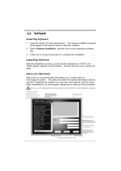
...,please set Outlook Express as your area or the area cl ose to send out the mail. Provide the name of the memor y module manufacturer. Motherboard Manual 5.2 SOFTWARE Installing Software 1. Before you use this information, you fix the problem. Send the mail out.
...,please set Outlook Express as your area or the area cl ose to send out the mail. Provide the name of the memor y module manufacturer. Motherboard Manual 5.2 SOFTWARE Installing Software 1. Before you use this information, you fix the problem. Send the mail out.
Setup Manual
Page 27
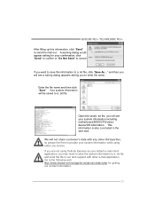
...save the system information to a .txt file and send the file to provide your system information including motherboard/BIOS/CPU/video/ device/OS information. Your system information will see a saving dialog appears asking you are...txt file. Open the saved .txt file, you will be saved to the following web http://www.biostar.com.tw/app/en-us/about/contact.php for your default e-mail client application, you will not ..., click "Send" to enter file name. GF8100 M2+ TE/GF8200C M2+ After filling up this information to cancel. This information is also concluded in the sent mail.
...save the system information to a .txt file and send the file to provide your system information including motherboard/BIOS/CPU/video/ device/OS information. Your system information will see a saving dialog appears asking you are...txt file. Open the saved .txt file, you will be saved to the following web http://www.biostar.com.tw/app/en-us/about/contact.php for your default e-mail client application, you will not ..., click "Send" to enter file name. GF8100 M2+ TE/GF8200C M2+ After filling up this information to cancel. This information is also concluded in the sent mail.
Setup Manual
Page 28
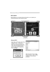
... information AMI BIOS Clear CMOS function (Only for AWARD BIOS) Online Update function (Only for AMI BIOS) Save current BIOS to update your motherboard BIOS under Windows system. Motherboard Manual BIOS Update BIOS Update is a convenient utility which allows you to a .bin file Update BIOS with a BIOS file Once click on OK...
... information AMI BIOS Clear CMOS function (Only for AWARD BIOS) Online Update function (Only for AMI BIOS) Save current BIOS to update your motherboard BIOS under Windows system. Motherboard Manual BIOS Update BIOS Update is a convenient utility which allows you to a .bin file Update BIOS with a BIOS file Once click on OK...
Setup Manual
Page 30
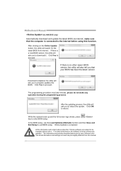
... function and then Save and Exit Setup to be slightly different from internet. All the information and content above are subject to exit BIOS setup. Motherboard Manual (for the latest BIOS from this function. make any operation during the programming process. If there is a new BIOS version, the utility will ask...
... function and then Save and Exit Setup to be slightly different from internet. All the information and content above are subject to exit BIOS setup. Motherboard Manual (for the latest BIOS from this function. make any operation during the programming process. If there is a new BIOS version, the utility will ask...

