Setup Manual
Page 1
... make changes to the contents here without obligation to the contents here and specially disclaims any implied warranties of this user's manual is not allowed without notice and we will not occur in writing. The vendor makes no guarantee that interference will not...protection against harmful interference in accordance with the limits of their respective companies. GF8100 M2+ TE/GF8200C M2+ Setup Manual FCC Information and Copyright This equipment has been tested and found in this user's manual. This equipment generates, uses, and can radiate radio frequency energy and, if not...
... make changes to the contents here without obligation to the contents here and specially disclaims any implied warranties of this user's manual is not allowed without notice and we will not occur in writing. The vendor makes no guarantee that interference will not...protection against harmful interference in accordance with the limits of their respective companies. GF8100 M2+ TE/GF8200C M2+ Setup Manual FCC Information and Copyright This equipment has been tested and found in this user's manual. This equipment generates, uses, and can radiate radio frequency energy and, if not...

Setup Manual
Page 3
GF8100 M2+ TE/GF8200C M2+ CHAPTER 1: INTRODUCTION 1.1 BEFORE YOU START Thank you take the motherboard out from dangerous area, such as heat source, humid air and water. 1.2 PACKAGE CHECKLIST IDE ... lighting. „ Always disconnect the computer from power outlet before operation. „ Before you for ATX Case X 1 Installation Guide X 1 Fully Setup Driver CD X 1 (full version manual files inside the case after installation.
GF8100 M2+ TE/GF8200C M2+ CHAPTER 1: INTRODUCTION 1.1 BEFORE YOU START Thank you take the motherboard out from dangerous area, such as heat source, humid air and water. 1.2 PACKAGE CHECKLIST IDE ... lighting. „ Always disconnect the computer from power outlet before operation. „ Before you for ATX Case X 1 Installation Guide X 1 Fully Setup Driver CD X 1 (full version manual files inside the case after installation.
Setup Manual
Page 4
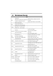
Motherboard Manual 1.3 MOTHERBOARD FEATURES SPEC Socket AM2+ AMD 64 Architecture enables 32 and 64 bit AMD Athlon 64 / Athlon 64 FX / Athlon 64 x2 CPU computing / Sempron / PhenomX3 processors Supports Hyper Transport 3.0 and PowerNow (Maximum Watt: 95W) Support HyperTransport 3.0 FSB Supports up to 5.2 GT/s Bandwidth Chipset GF8100 M2+ TE: GeForce 8100 GF8200C M2+ : GeForce 8200...
Motherboard Manual 1.3 MOTHERBOARD FEATURES SPEC Socket AM2+ AMD 64 Architecture enables 32 and 64 bit AMD Athlon 64 / Athlon 64 FX / Athlon 64 x2 CPU computing / Sempron / PhenomX3 processors Supports Hyper Transport 3.0 and PowerNow (Maximum Watt: 95W) Support HyperTransport 3.0 FSB Supports up to 5.2 GT/s Bandwidth Chipset GF8100 M2+ TE: GeForce 8100 GF8200C M2+ : GeForce 8200...
Setup Manual
Page 6
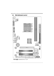
Motherboard Manual 1.5 MOTHERBOARD LAYOUT JKBMS J ATXPW R2 J KB_PW R JATXPWR1 S ocket AM 2+ DVI VG A DIMMA1 DIMMB1 ID E JUSB1 JUS BPWR1 JUSBLAN1 J CFAN JAUDIO1 GeForce 8100/8200 JUSBPWR2 BAT1 LAN PEX16_1 JAU DIOF Codec JCOM J CDIN JPRNT PCI1 PCI2 FDD Note: ■ represents the 1st pin. JUSB4 JUSB2 JUSB3 Super I/O JCMOS B IO S SATA1 SATA3 SATA2 SATA4 JS FAN JPANEL1 4
Motherboard Manual 1.5 MOTHERBOARD LAYOUT JKBMS J ATXPW R2 J KB_PW R JATXPWR1 S ocket AM 2+ DVI VG A DIMMA1 DIMMB1 ID E JUSB1 JUS BPWR1 JUSBLAN1 J CFAN JAUDIO1 GeForce 8100/8200 JUSBPWR2 BAT1 LAN PEX16_1 JAU DIOF Codec JCOM J CDIN JPRNT PCI1 PCI2 FDD Note: ■ represents the 1st pin. JUSB4 JUSB2 JUSB3 Super I/O JCMOS B IO S SATA1 SATA3 SATA2 SATA4 JS FAN JPANEL1 4
Setup Manual
Page 8
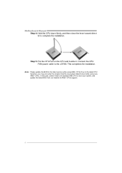
... buckle it. Connect the CPU FAN power cable to boot your system, and update the latest BIOS from our website for AM2+ CPUs support. 6 Motherboard Manual Step 4: Hold the CPU down firmly, and then close the lever toward direct B to the latest version while using new AM2+ CPUs. Note: Please update...
... buckle it. Connect the CPU FAN power cable to boot your system, and update the latest BIOS from our website for AM2+ CPUs support. 6 Motherboard Manual Step 4: Hold the CPU down firmly, and then close the lever toward direct B to the latest version while using new AM2+ CPUs. Note: Please update...
Setup Manual
Page 10
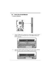
Memory Modules 1. Align a DIMM on the slot such that the notch on the DIMM matches the break on the Slot. 2. Insert the DIMM vertically and firmly into the slot until the retaining chip snap back in place and the DIMM is properly seated. 8 DIMMA1 DIMMB 1 Motherboard Manual 2.3 INSTALLING SYSTEM MEMORY A. Unlock a DIMM slot by pressing the retaining clips outward.
Memory Modules 1. Align a DIMM on the slot such that the notch on the DIMM matches the break on the Slot. 2. Insert the DIMM vertically and firmly into the slot until the retaining chip snap back in place and the DIMM is properly seated. 8 DIMMA1 DIMMB 1 Motherboard Manual 2.3 INSTALLING SYSTEM MEMORY A. Unlock a DIMM slot by pressing the retaining clips outward.
Setup Manual
Page 12
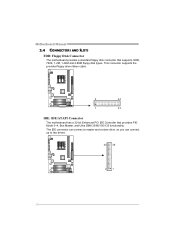
This connector supports the provided floppy drive ribbon cable. 2 34 1 33 IDE: IDE/ATAPI Connector The motherboard has a 32-bit Enhanced PCI IDE Controller that supports 360K, 720K, 1.2M, 1.44M and 2.88M floppy disk types. The IDE connector can connect a master and a slave drive, so you can connect up to two drives. 40 39 21 10 Motherboard Manual 2.4 CONNECTORS AND SLOTS FDD: Floppy Disk Connector The motherboard provides a standard floppy disk connector that provides PIO Mode 0~4, Bus Master, and Ultra DMA 33/66/100/133 functionality.
This connector supports the provided floppy drive ribbon cable. 2 34 1 33 IDE: IDE/ATAPI Connector The motherboard has a 32-bit Enhanced PCI IDE Controller that supports 360K, 720K, 1.2M, 1.44M and 2.88M floppy disk types. The IDE connector can connect a master and a slave drive, so you can connect up to two drives. 40 39 21 10 Motherboard Manual 2.4 CONNECTORS AND SLOTS FDD: Floppy Disk Connector The motherboard provides a standard floppy disk connector that provides PIO Mode 0~4, Bus Master, and Ultra DMA 33/66/100/133 functionality.
Setup Manual
Page 14
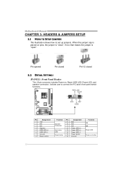
... LED, and speaker connection. When the jumper cap is placed on pins, the jumper is "close", if not, that means the jumper is "open". Motherboard Manual CHAPTER 3: HEADERS & JUMPERS SETUP 3.1 HOW TO SETUP JUMPERS The illustration shows how to connect the PC case's front panel switch functions.
... LED, and speaker connection. When the jumper cap is placed on pins, the jumper is "close", if not, that means the jumper is "open". Motherboard Manual CHAPTER 3: HEADERS & JUMPERS SETUP 3.1 HOW TO SETUP JUMPERS The illustration shows how to connect the PC case's front panel switch functions.
Setup Manual
Page 16
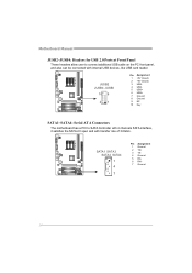
... The motherboard has a PCI to connect additional USB cable on the PC front panel, and also can be connected with transfer rate of 3.0Gb/s. Motherboard Manual JUSB2~JUSB4: Headers for USB 2.0 Ports at Front Panel These headers allow user to SATA Controller with 4 channels SATA interface, it satisfies the SATA 2.0 spec...
... The motherboard has a PCI to connect additional USB cable on the PC front panel, and also can be connected with transfer rate of 3.0Gb/s. Motherboard Manual JUSB2~JUSB4: Headers for USB 2.0 Ports at Front Panel These headers allow user to SATA Controller with 4 channels SATA interface, it satisfies the SATA 2.0 spec...
Setup Manual
Page 18
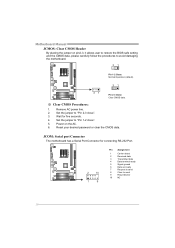
...: 1. Power on pin2-3, it allows user to restore the BIOS safe setting and the CMOS data, please carefully follow the procedures to "Pin 1-2 close ". 3. Motherboard Manual JCMOS: Clear CMOS Header By placing the jumper on the AC. 6. Wait for connecting RS-232 Port. 2 10 1 9 Pin Assignment 1 Carrier detect 2 Received data 3 Transmitted...
...: 1. Power on pin2-3, it allows user to restore the BIOS safe setting and the CMOS data, please carefully follow the procedures to "Pin 1-2 close ". 3. Motherboard Manual JCMOS: Clear CMOS Header By placing the jumper on the AC. 6. Wait for connecting RS-232 Port. 2 10 1 9 Pin Assignment 1 Carrier detect 2 Received data 3 Transmitted...
Setup Manual
Page 20
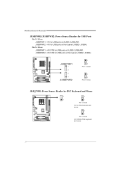
JUSBPWR2: +5V for USB ports at front panel (JUSB2~JUSB4). JUSBPWR1 1 3 3 1 JUSBPWR2 1 3 Pin 1-2 close 1 3 Pin 2-3 close JKB_PWR: Power Source Header for PS/2 Keyboard and Mouse 3 3 1 1 Pin 1-2 close +5V for PS/2 keyboard and mouse. 3 1 Pin 2-3 close +5V STB for PS/2 keyboard and mouse. 18 JUSBPWR2: +5V STB for USB ports at front panel (JUSB2~JUSB4). Pin 2-3 Close: JUSBPWR1: +5V STB for USB ports at JUSB1/JUSBLAN1. Motherboard Manual JUSBPWR1/JUSBPWR2: Power Source Headers for USB Ports Pin 1-2 Close: JUSBPWR1: +5V for USB ports at JUSB1/JUSBLAN1.
JUSBPWR2: +5V for USB ports at front panel (JUSB2~JUSB4). JUSBPWR1 1 3 3 1 JUSBPWR2 1 3 Pin 1-2 close 1 3 Pin 2-3 close JKB_PWR: Power Source Header for PS/2 Keyboard and Mouse 3 3 1 1 Pin 1-2 close +5V for PS/2 keyboard and mouse. 3 1 Pin 2-3 close +5V STB for PS/2 keyboard and mouse. 18 JUSBPWR2: +5V STB for USB ports at front panel (JUSB2~JUSB4). Pin 2-3 Close: JUSBPWR1: +5V STB for USB ports at JUSB1/JUSBLAN1. Motherboard Manual JUSBPWR1/JUSBPWR2: Power Source Headers for USB Ports Pin 1-2 Close: JUSBPWR1: +5V for USB ports at JUSB1/JUSBLAN1.
Setup Manual
Page 22
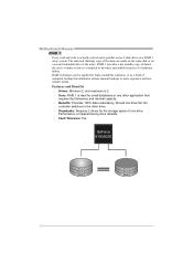
Motherboard Manual RAID 1: Every read and write is 2. - Drives: Minimum 2, and maximum is actually carried out in parallel across 2 disk drives in the array. Benefits: Provides 100% ... can reside on the same disk or on a second redundant drive in a RAID 1 array system. The mirrored (backup) copy of automatic backup that eliminates tedious manual backups to the other application that requires fault tolerance and minimal capacity. -
Motherboard Manual RAID 1: Every read and write is 2. - Drives: Minimum 2, and maximum is actually carried out in parallel across 2 disk drives in the array. Benefits: Provides 100% ... can reside on the same disk or on a second redundant drive in a RAID 1 array system. The mirrored (backup) copy of automatic backup that eliminates tedious manual backups to the other application that requires fault tolerance and minimal capacity. -
Setup Manual
Page 24
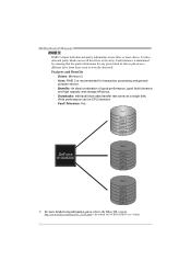
... to download the NVIDIA RAID User's Guide. 22 Features and Benefits - Fault Tolerance: Yes. Drawbacks: Individual block data transfer rate same as a single disk. Motherboard Manual RAID 5: RAID 5 stripes both data and parity information across all the drives in the array. Drives: Minimum 3. - Benefits: An ideal combination of data is recommended...
... to download the NVIDIA RAID User's Guide. 22 Features and Benefits - Fault Tolerance: Yes. Drawbacks: Individual block data transfer rate same as a single disk. Motherboard Manual RAID 5: RAID 5 stripes both data and parity information across all the drives in the array. Drives: Minimum 3. - Benefits: An ideal combination of data is recommended...
Setup Manual
Page 25
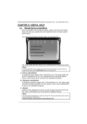
GF8100 M2+ TE/GF8200C M2+ CHAPTER 5: USEFUL HELP 5.1 DRIVER INSTALLATION NOTE After you insert the CD The setup guide will auto detect your motherboard and operating system. The setup guide ... to launch the installation program. Please download the latest version of Acrobat Reader software from the paperback manual, we also provide manual in the Driver CD. Click on each software title to browse for available manual. B. C. Note: If this window didn't show up after you installed your operating system, please insert the Fully...
GF8100 M2+ TE/GF8200C M2+ CHAPTER 5: USEFUL HELP 5.1 DRIVER INSTALLATION NOTE After you insert the CD The setup guide will auto detect your motherboard and operating system. The setup guide ... to launch the installation program. Please download the latest version of Acrobat Reader software from the paperback manual, we also provide manual in the Driver CD. Click on each software title to browse for available manual. B. C. Note: If this window didn't show up after you installed your operating system, please insert the Fully...
Setup Manual
Page 26
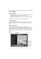
Motherboard Manual 5.2 SOFTWARE Installing Software 1. Select Software Installation, and then click on the desktop. Double-click the icon to the optical drive. Before you use this information, ...
Motherboard Manual 5.2 SOFTWARE Installing Software 1. Select Software Installation, and then click on the desktop. Double-click the icon to the optical drive. Before you use this information, ...
Setup Manual
Page 28
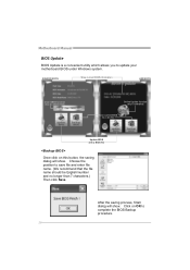
..., finish dialog will show . Click on this button, the saving dialog will show . Choose the position to update your motherboard BIOS under Windows system. Motherboard Manual BIOS Update BIOS Update is a convenient utility which allows you to save file and enter file name. (We recommend that the file name should be...
..., finish dialog will show . Click on this button, the saving dialog will show . Choose the position to update your motherboard BIOS under Windows system. Motherboard Manual BIOS Update BIOS Update is a convenient utility which allows you to save file and enter file name. (We recommend that the file name should be...
Setup Manual
Page 30
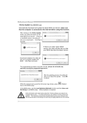
... Online Update button, the utility will search for AMI BIOS only) Automatically download and update the latest BIOS via internet; Click Yes to reboot. Motherboard Manual (for the latest BIOS from this function. make any operation during the programming process. Click Yes to enter BIOS setup. For better performance, the software... the latest version. In the BIOS setup, use the Load Optimized Defaults function and then Save and Exit Setup to the internet before using this manual. 28
... Online Update button, the utility will search for AMI BIOS only) Automatically download and update the latest BIOS via internet; Click Yes to reboot. Motherboard Manual (for the latest BIOS from this function. make any operation during the programming process. Click Yes to enter BIOS setup. For better performance, the software... the latest version. In the BIOS setup, use the Load Optimized Defaults function and then Save and Exit Setup to the internet before using this manual. 28
Setup Manual
Page 32
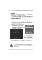
Motherboard Manual BIO-Flasher BIO-Flasher is built in the BIOS chip. Updating BIOS with FAT32/16 format and single partition. Go to the website to enter ...
Motherboard Manual BIO-Flasher BIO-Flasher is built in the BIOS chip. Updating BIOS with FAT32/16 format and single partition. Go to the website to enter ...
Setup Manual
Page 34
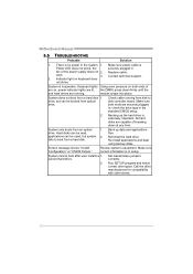
... are running from a hard disk 1. Call the drive manufacturers for compatibility with other drives. 32 drive. Re-install applications and data using backup disks. Motherboard Manual 5.5 TROUBLESHOOTING Probable Solution 1. Make sure power cable is inoperative. check the drive type in the standard CMOS setup. 2. System only boots from a hard disk. second...
... are running from a hard disk 1. Call the drive manufacturers for compatibility with other drives. 32 drive. Re-install applications and data using backup disks. Motherboard Manual 5.5 TROUBLESHOOTING Probable Solution 1. Make sure power cable is inoperative. check the drive type in the standard CMOS setup. 2. System only boots from a hard disk. second...
Setup Manual
Page 52
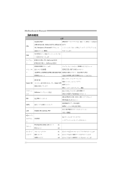
Motherboard Manual JAPANESE 仕様 Socket AM2+ AMD 64 32ビットと64 AMD Athlon 64 / Athlon 64 FX / Althlon 64 能です CPU X2 / Sempron / PhenomX3 3.0 95W) 5.2 GT/s FSB ート3.0 GF8100 M2+ TE: GeForce 8100 ト GF8200C M2+ : GeForce 8200 DDR2 DIMM x 2 8GB DDR2 DDR2 533 / 667 / 800 リ 各...
Motherboard Manual JAPANESE 仕様 Socket AM2+ AMD 64 32ビットと64 AMD Athlon 64 / Athlon 64 FX / Althlon 64 能です CPU X2 / Sempron / PhenomX3 3.0 95W) 5.2 GT/s FSB ート3.0 GF8100 M2+ TE: GeForce 8100 ト GF8200C M2+ : GeForce 8200 DDR2 DIMM x 2 8GB DDR2 DDR2 533 / 667 / 800 リ 各...

