
Setup Manual
Page 5
GF7025-M2 Ver 6.x ALC662 5.1 channels audio out High Definition Audio PCI slot x2 PCI Express x16 slot x1 PCI Express x 1 slot x1 Floppy connector x1 Printer Port connector x1 IDE Connector x1 SATA Connector x4 Front Panel Connector x1 Front Audio Connector...LAN port x1 USB Port x4 Audio Jack x6 BoardSize 208 mm(W) x 244 mm(L) Special Features RAID 0 / 1 / 5 / 0+1support Windows 2000 / XP / VISTA OS Support Biostar Reserves the right to add or remove support for any OS With or without notice. Ver 5.x ALC888 Sound 7.1 channels audio out High Definition Audio...
GF7025-M2 Ver 6.x ALC662 5.1 channels audio out High Definition Audio PCI slot x2 PCI Express x16 slot x1 PCI Express x 1 slot x1 Floppy connector x1 Printer Port connector x1 IDE Connector x1 SATA Connector x4 Front Panel Connector x1 Front Audio Connector...LAN port x1 USB Port x4 Audio Jack x6 BoardSize 208 mm(W) x 244 mm(L) Special Features RAID 0 / 1 / 5 / 0+1support Windows 2000 / XP / VISTA OS Support Biostar Reserves the right to add or remove support for any OS With or without notice. Ver 5.x ALC888 Sound 7.1 channels audio out High Definition Audio...

Setup Manual
Page 13
This connector supports the prov ided f loppy drive ribbon cables. 2 34 1 33 IDE1: Hard Disk Conne ctor The motherboard has a 32-bit Enhanced PCI IDE Controller that supports 360K, 720K, 1.2M, 1.44M and 2.88M floppy disk ty pes. The IDE connector can connect a master and a slave drive, so y ou can connect up to two hard disk driv es. 40 39 21 13 GF7025-M2 2.4 CONNECT ORS AND SLOT S FDD1: Floppy Disk Conne ctor The motherboard prov ides a standard floppy disk connector that prov ides PIO Mode 0~4, Bus Master, and Ultra DMA 33/66/100/133 f unctionality.
This connector supports the prov ided f loppy drive ribbon cables. 2 34 1 33 IDE1: Hard Disk Conne ctor The motherboard has a 32-bit Enhanced PCI IDE Controller that supports 360K, 720K, 1.2M, 1.44M and 2.88M floppy disk ty pes. The IDE connector can connect a master and a slave drive, so y ou can connect up to two hard disk driv es. 40 39 21 13 GF7025-M2 2.4 CONNECT ORS AND SLOT S FDD1: Floppy Disk Conne ctor The motherboard prov ides a standard floppy disk connector that prov ides PIO Mode 0~4, Bus Master, and Ultra DMA 33/66/100/133 f unctionality.

Setup Manual
Page 14
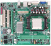
... 4GB/s simultaneously per direction; 500MB/s in total. - This PCI slot is equipped with 2 standard PCI slots. Motherboard Manual PCI-EX16: PCI-Express x16 Slot - PCI-EX1_1: PCI-Express x1 Slot - Maximum theoretical realized bandwidth of 2.5GB/s on the data pins. - 2X bandwidth ov er the traditional PCI architecture. PCI-EX1_1 PCI-EX16 PCI1~PCI2: Pe riphe ral Component Interconne...
... 4GB/s simultaneously per direction; 500MB/s in total. - This PCI slot is equipped with 2 standard PCI slots. Motherboard Manual PCI-EX16: PCI-Express x16 Slot - PCI-EX1_1: PCI-Express x1 Slot - Maximum theoretical realized bandwidth of 2.5GB/s on the data pins. - 2X bandwidth ov er the traditional PCI architecture. PCI-EX1_1 PCI-EX16 PCI1~PCI2: Pe riphe ral Component Interconne...

Setup Manual
Page 17
SATA2 SATA4 SATA1 SATA3 14 7 Pin Assignment 1 Ground 2 TX+ 3 TX4 Ground 5 RX6 RX+ 7 Ground 17 J USB3 JU SB2 JUSB4 12 9 10 Pin Assignment 1 +5V (fused) 2 +5V (fused) 3 USB4 USB5 USB+ 6 USB+ 7 Ground 8 Ground 9 Key 10 NC SATA1~SATA4: Se rial ATA Connectors The motherboard has a PCI to connect additional USB cable on the PC f ront panel, and also can be connected with 4 channels SATA interf ace. GF7025-M2 JUSB2/JUSB3/JUSB4: He ade rs for USB 2.0 Ports at Front Panel This header allows user to SATA Controller with internal USB devices, like USB card reader.
SATA2 SATA4 SATA1 SATA3 14 7 Pin Assignment 1 Ground 2 TX+ 3 TX4 Ground 5 RX6 RX+ 7 Ground 17 J USB3 JU SB2 JUSB4 12 9 10 Pin Assignment 1 +5V (fused) 2 +5V (fused) 3 USB4 USB5 USB+ 6 USB+ 7 Ground 8 Ground 9 Key 10 NC SATA1~SATA4: Se rial ATA Connectors The motherboard has a PCI to connect additional USB cable on the PC f ront panel, and also can be connected with 4 channels SATA interf ace. GF7025-M2 JUSB2/JUSB3/JUSB4: He ade rs for USB 2.0 Ports at Front Panel This header allows user to SATA Controller with internal USB devices, like USB card reader.

Setup Manual
Page 18
... JAUDIO F1: Front Panel Audio Heade r This header allows user to connect the audio source f rom the v ariaty dev ices, like CD-ROM, DVD-ROM, PCI sound card, PCI TV turner card etc.. 14 Pin Assignment 1 Left Channel Input 2 Ground 3 Ground 4 Right Channel Input 18
... JAUDIO F1: Front Panel Audio Heade r This header allows user to connect the audio source f rom the v ariaty dev ices, like CD-ROM, DVD-ROM, PCI sound card, PCI TV turner card etc.. 14 Pin Assignment 1 Left Channel Input 2 Ground 3 Ground 4 Right Channel Input 18

Setup Manual
Page 19
... "Pin 1-2 close ". 3. Reset y our desired password or clear the CMOS data. 19 Set the jumper to "Pin 2-3 close ". 5. GF7025-M2 JSPDIF_O UT1: Digital Audio-out Conne ctor This connector allows user to connect the PCI bracket SPDIF output header. 13 Pin Assignment 1 +5V 2 SPDIF_OUT 3 Ground JCMO S1: Cle ar CMOS Heade r By placing...
... "Pin 1-2 close ". 3. Reset y our desired password or clear the CMOS data. 19 Set the jumper to "Pin 2-3 close ". 5. GF7025-M2 JSPDIF_O UT1: Digital Audio-out Conne ctor This connector allows user to connect the PCI bracket SPDIF output header. 13 Pin Assignment 1 +5V 2 SPDIF_OUT 3 Ground JCMO S1: Cle ar CMOS Heade r By placing...

Setup Manual
Page 28
... control utility, features three user-friendly functions including Overclock Manager, Overvoltage Manager, and Hardware Monitor. In addition, the frequency status of CPU, memory, VGA and PCI along with just one . 6.2 SYST EM REQUIREMENT OS Support: Windows 98 SE, Windows Me, Windows 2000, Windows XP, Windows Vista DirectX: DirectX 8.1 or above. (The...
... control utility, features three user-friendly functions including Overclock Manager, Overvoltage Manager, and Hardware Monitor. In addition, the frequency status of CPU, memory, VGA and PCI along with just one . 6.2 SYST EM REQUIREMENT OS Support: Windows 98 SE, Windows Me, Windows 2000, Windows XP, Windows Vista DirectX: DirectX 8.1 or above. (The...

Setup Manual
Page 30
...; III] will see is for invoking respective panels. Motherboard Manual 6.4 WARPSPEEDER™ III 1. Display the CPU Speed, CPU external clock, Memory clock, VGA clock, and PCI clock information. Now you will be launched. Main Panel contains fe ature s as follows: a. T he On/Off button is Main Panel. Contains About, Voltage/Overclock...
...; III] will see is for invoking respective panels. Motherboard Manual 6.4 WARPSPEEDER™ III 1. Display the CPU Speed, CPU external clock, Memory clock, VGA clock, and PCI clock information. Now you will be launched. Main Panel contains fe ature s as follows: a. T he On/Off button is Main Panel. Contains About, Voltage/Overclock...

Setup Manual
Page 54
GF7025-M2 BIOS Setup BIOS Setup 1 1 Main Menu 3 2 Standard CMOS Features 7 3 Advanced BIOS Features 9 4 Advanced Chipset Features 16 5 Integrated Peripherals 18 6 Power Management Setup 25 7 PnP/PCI Configurations 29 8 PC Health Status 31 9 Performance Booster Zone 34 i
GF7025-M2 BIOS Setup BIOS Setup 1 1 Main Menu 3 2 Standard CMOS Features 7 3 Advanced BIOS Features 9 4 Advanced Chipset Features 16 5 Integrated Peripherals 18 6 Power Management Setup 25 7 PnP/PCI Configurations 29 8 PC Health Status 31 9 Performance Booster Zone 34 i

Setup Manual
Page 56
...Page Setup Menu - PCI Bus Support This PHOENIX-AWARD BIOS also supports Version 3.0 of Advanced Configuration and Power interface specification (ACPI). Supported CPUs This PHOENIX-AWARD BIOS supports the AMD CPU. DRAM Support DDR2 SDRAM (Double Data Rate Synchronous DRAM) is supported. GF7025-M2 ACPI Support Phoenix-...Award ACPI BIOS support Version 1.0b of the Intel PCI (Peripheral Component Interconnect) local bus specification.
...Page Setup Menu - PCI Bus Support This PHOENIX-AWARD BIOS also supports Version 3.0 of Advanced Configuration and Power interface specification (ACPI). Supported CPUs This PHOENIX-AWARD BIOS supports the AMD CPU. DRAM Support DDR2 SDRAM (Double Data Rate Synchronous DRAM) is supported. GF7025-M2 ACPI Support Phoenix-...Award ACPI BIOS support Version 1.0b of the Intel PCI (Peripheral Component Interconnect) local bus specification.

Setup Manual
Page 58
...optimized for this system. These configurations are set. 4 Performance Booster Zone This submenu allows you to change CPU Vcore Voltage and CPU/PCI clock. (However, we suggest you to configure the power management features. PC Health Status This submenu allows you to reload the ...you to monitor the hardware of the BIOS. PnP/PCI Configurations This submenu allows you to configure advanced features of your system. GF7025-M2 Advanced BIOS Features This submenu allows you to configure certain "Plug and Play" and PCI options. Advanced Chipset Features This submenu allows you ...
...optimized for this system. These configurations are set. 4 Performance Booster Zone This submenu allows you to change CPU Vcore Voltage and CPU/PCI clock. (However, we suggest you to configure the power management features. PC Health Status This submenu allows you to reload the ...you to monitor the hardware of the BIOS. PnP/PCI Configurations This submenu allows you to configure advanced features of your system. GF7025-M2 Advanced BIOS Features This submenu allows you to configure certain "Plug and Play" and PCI options. Advanced Chipset Features This submenu allows you ...

Setup Manual
Page 66
Summary screen means system configuration and PCI device listing. Cache Setup 12 Summary Screen Show This item allows you to enable/disable the summary screen. The Choices: Non-OS2 (default), OS2. The ... Logo" shows when system boots The Choices: Enabled (default), Disabled. Small Logo(EPA) Show This item allows you to select whether the "Small Logo" shows. GF7025-M2 OS Select For DRAM > 64MB A choice other than Non-OS2 is only used for OS2 systems with memory exceeding 64MB. Enabled (default) "Small Logo" shows...
Summary screen means system configuration and PCI device listing. Cache Setup 12 Summary Screen Show This item allows you to enable/disable the summary screen. The Choices: Non-OS2 (default), OS2. The ... Logo" shows when system boots The Choices: Enabled (default), Disabled. Small Logo(EPA) Show This item allows you to select whether the "Small Logo" shows. GF7025-M2 OS Select For DRAM > 64MB A choice other than Non-OS2 is only used for OS2 systems with memory exceeding 64MB. Enabled (default) "Small Logo" shows...

Setup Manual
Page 70
... Speed The Choices: AUTO (default), 1x, 2x, 3x, 4x, 5x. 16 This chipset manage bus speeds and access to system memory resources, such as DRAM. GF7025-M2 4 Advanced Chipset Features This submenu allows you to configure the specific features of on your system have been changed unless you are suspicious that came...
... Speed The Choices: AUTO (default), 1x, 2x, 3x, 4x, 5x. 16 This chipset manage bus speeds and access to system memory resources, such as DRAM. GF7025-M2 4 Advanced Chipset Features This submenu allows you to configure the specific features of on your system have been changed unless you are suspicious that came...

Setup Manual
Page 73
...) fields let you to enable or disable SATA Primary/Secondary RAID. The Choices: Auto (default), Mode0, Mode1, Mode2, Mode3, Mode4. 19 GF7025-M2 MCP Storage Config SATA Operation Mode This option allows you set a PIO mode (0-4) for each device. In Auto mode, the system automatically determines ...the best mode for two IDE channels. On-chip IDE Channel 0 The motherboard chipset contains a PCI IDE interface with support for each of the IDE devices that the onboard IDE interface supports. The Choices: Enabled (default), Disabled. SATA Pri...
...) fields let you to enable or disable SATA Primary/Secondary RAID. The Choices: Auto (default), Mode0, Mode1, Mode2, Mode3, Mode4. 19 GF7025-M2 MCP Storage Config SATA Operation Mode This option allows you set a PIO mode (0-4) for each device. In Auto mode, the system automatically determines ...the best mode for two IDE channels. On-chip IDE Channel 0 The motherboard chipset contains a PCI IDE interface with support for each of the IDE devices that the onboard IDE interface supports. The Choices: Enabled (default), Disabled. SATA Pri...

Setup Manual
Page 77
...port as Standard Printer Port. The Choices: Auto (default), Always Enable. You may need to disable this feature if you to decide to active whether PCI Slot or on the system board. The Choices: SHADOW (default), Base Memory(640K). 23 The Choices: 3 (default), 1. The Choices: SPP (... you to choose the USB memory type. The Choices: PCIEx (default), PCI Slot, Onboard. The Choices: V1.1+V2.0 (default), Disabled, V1.1 USB Memory Type This option allows you to control the onboard GPU. GF7025-M2 Parallel Port Mode This item allows you to determine how the parallel port...
...port as Standard Printer Port. The Choices: Auto (default), Always Enable. You may need to disable this feature if you to decide to active whether PCI Slot or on the system board. The Choices: SHADOW (default), Base Memory(640K). 23 The Choices: 3 (default), 1. The Choices: SPP (... you to choose the USB memory type. The Choices: PCIEx (default), PCI Slot, Onboard. The Choices: V1.1+V2.0 (default), Disabled, V1.1 USB Memory Type This option allows you to control the onboard GPU. GF7025-M2 Parallel Port Mode This item allows you to determine how the parallel port...

Setup Manual
Page 83
... Data The system BIOS supports the PnP feature which requires the system to record which allows I/O devices to the memory locations. GF7025-M2 7 PnP/PCI Configurations This section describes configuring the PCI bus system. PCI, or Personal Computer Interconnect, is called ESCD. Every peripheral device has a node, which is a system which resources are reserved in...
... Data The system BIOS supports the PnP feature which requires the system to record which allows I/O devices to the memory locations. GF7025-M2 7 PnP/PCI Configurations This section describes configuring the PCI bus system. PCI, or Personal Computer Interconnect, is called ESCD. Every peripheral device has a node, which is a system which resources are reserved in...

Setup Manual
Page 84
GF7025-M2 The above settings will detect the system resources and automatically assign the relative ...for Transaction packets (TLP). IRQ-5 assigned to PCI Device IRQ-7 assigned to PCI Device IRQ-9 assigned to PCI Device IRQ-10 assigned to PCI Device IRQ-11 assigned to PCI Device IRQ-14 assigned to PCI Device PCI / VGA Palette Snoop Some old graphic controllers need...that will need to "snoop" on the screen only if "Manual" is assigned to the PCI Bus or provides for the resources controlled by function. PCI / ISA PnP signify that there are no IRQ/DMA and I/O port conflicts. Be sure that...
GF7025-M2 The above settings will detect the system resources and automatically assign the relative ...for Transaction packets (TLP). IRQ-5 assigned to PCI Device IRQ-7 assigned to PCI Device IRQ-9 assigned to PCI Device IRQ-10 assigned to PCI Device IRQ-11 assigned to PCI Device IRQ-14 assigned to PCI Device PCI / VGA Palette Snoop Some old graphic controllers need...that will need to "snoop" on the screen only if "Manual" is assigned to the PCI Bus or provides for the resources controlled by function. PCI / ISA PnP signify that there are no IRQ/DMA and I/O port conflicts. Be sure that...

