

GeForce 6100-M9 user's manual
Page 3
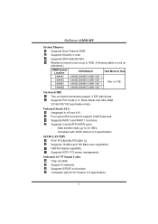
...commonly used legacy Super I /O Chip: ITE IT8712F. Environment Control initiatives, H/W Monitor Fan Speed Controller ITE's "Smart Guardian" function 1 Chipset North Bridge: nVIDIA GeForce6100. Super I /O functionality. One PCI-E x16 slot. Supports AMD Athlon 64 FX/ Athlon 64/ Athlon 64 X2 processor. Supports AMD Cool'n'Quiet Technology. GeForce 6100-M9 CHAPTER 1: INTRODUCTION 1.1 MOTHERBOARD FEATURES CPU Supports Socket 939. Slot Two PCI bus master slots. Dimensions Micro ATX Form Factor: 24.5cm (L) x 24.45cm (W) Operating System Supporting Supports Windows...
...commonly used legacy Super I /O Chip: ITE IT8712F. Environment Control initiatives, H/W Monitor Fan Speed Controller ITE's "Smart Guardian" function 1 Chipset North Bridge: nVIDIA GeForce6100. Super I /O functionality. One PCI-E x16 slot. Supports AMD Athlon 64 FX/ Athlon 64/ Athlon 64 X2 processor. Supports AMD Cool'n'Quiet Technology. GeForce 6100-M9 CHAPTER 1: INTRODUCTION 1.1 MOTHERBOARD FEATURES CPU Supports Socket 939. Slot Two PCI bus master slots. Dimensions Micro ATX Form Factor: 24.5cm (L) x 24.45cm (W) Operating System Supporting Supports Windows...
GeForce 6100-M9 user's manual
Page 4
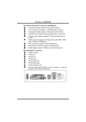
...-board connectors support 4 IDE disk drives. Supports ACPI, PCI power management. Supports S/PDIF out function. Onboard Serial ATA Integrated in total. Supports RAID 0 and RAID 1 functions. Compliant with AC'97 Version 2.3 specification. 2 Onboard AC'97 Sound Codec Chip: ALC655 Support 6 channels. Four serial ATA connectors support 2 SATA devices. Supports 10 Mb/s and 100 Mb/s auto-negotiation. Supports 2 serial ATA (SATA) ports. - Supports DDR-266/333/400. Maximum memory size is up to 4GB. (Following table is only for reference.) DIMM Socket Location DDR...
...-board connectors support 4 IDE disk drives. Supports ACPI, PCI power management. Supports S/PDIF out function. Onboard Serial ATA Integrated in total. Supports RAID 0 and RAID 1 functions. Compliant with AC'97 Version 2.3 specification. 2 Onboard AC'97 Sound Codec Chip: ALC655 Support 6 channels. Four serial ATA connectors support 2 SATA devices. Supports 10 Mb/s and 100 Mb/s auto-negotiation. Supports 2 serial ATA (SATA) ports. - Supports DDR-266/333/400. Maximum memory size is up to 4GB. (Following table is only for reference.) DIMM Socket Location DDR...
GeForce 6100-M9 user's manual
Page 5
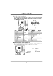
... CD-ROM audio-in connector. GeForce 6100-M9 Internal On-board I /O Connectors 4 USB 2.0 ports. 1 VGA port. 1 Serial port. 1 Printer port. 1 RJ-45 LAN jack. 1 PS/2 Mouse port. 1 PS/2 Keyboard port. 1 Vertical audio port including 1 Line-in connector, 1 Line-out connector, and 1 MIC-in device. 1 front audio header supports front panel audio function. 1 S/PDIF-Out connector supports digital audio-out function. 1 chassis open header supports PC case-opened warning function. 1 FDD connector supports 2 Floppy drives with 360K, 720K, 1.2M, 1.44M and 2.88Mbytes. 2 IDE connectors support 4 hard disk...
... CD-ROM audio-in connector. GeForce 6100-M9 Internal On-board I /O Connectors 4 USB 2.0 ports. 1 VGA port. 1 Serial port. 1 Printer port. 1 RJ-45 LAN jack. 1 PS/2 Mouse port. 1 PS/2 Keyboard port. 1 Vertical audio port including 1 Line-in connector, 1 Line-out connector, and 1 MIC-in device. 1 front audio header supports front panel audio function. 1 S/PDIF-Out connector supports digital audio-out function. 1 chassis open header supports PC case-opened warning function. 1 FDD connector supports 2 Floppy drives with 360K, 720K, 1.2M, 1.44M and 2.88Mbytes. 2 IDE connectors support 4 hard disk...
GeForce 6100-M9 user's manual
Page 11
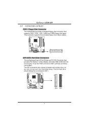
...: Hard Disk Connectors The motherboard has a 32-bit Enhanced PCI IDE Controller that supports 360K, 720K, 1.2M, 1.44M and 2.88M floppy disk types. The first hard drive should always be connected to four hard disk drives. It has two HDD connectors IDE1 (primary) and IDE2 (secondary). The IDE connectors can connect a master and a slave drive, so you can connect up to IDE1. 40 39 2 IDE2 1 IDE1 9 GeForce 6100-M9 2.4 CONNECTORS AND SLOTS FDD1: Floppy Disk Connector The motherboard provides a standard floppy disk connector that provides PIO Mode 0~4, Bus Master...
...: Hard Disk Connectors The motherboard has a 32-bit Enhanced PCI IDE Controller that supports 360K, 720K, 1.2M, 1.44M and 2.88M floppy disk types. The first hard drive should always be connected to four hard disk drives. It has two HDD connectors IDE1 (primary) and IDE2 (secondary). The IDE connectors can connect a master and a slave drive, so you can connect up to IDE1. 40 39 2 IDE2 1 IDE1 9 GeForce 6100-M9 2.4 CONNECTORS AND SLOTS FDD1: Floppy Disk Connector The motherboard provides a standard floppy disk connector that provides PIO Mode 0~4, Bus Master...
GeForce 6100-M9 user's manual
Page 15
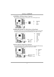
...: Serial ATA Connectors The motherboard has a PCI to SATA Controller with 2 channels SATA interface, it will provide +12V to connect additional USB cable on the PC front panel, and also can be connected with transfer rate of 3GB/s. Pin Assignment 4 3 1 +12V 2 +12V 1 2 3 Ground 4 Ground JUSB2/JUSB3: Headers for USB 2.0 Ports at Front Panel This header allows user to CPU power circuit. GeForce 6100-M9 JATXPWR2: ATX Power Source Connector By connecting this connector, it satisfies the SATA 2.0 spec and with internal USB devices, like USB card reader...
...: Serial ATA Connectors The motherboard has a PCI to SATA Controller with 2 channels SATA interface, it will provide +12V to connect additional USB cable on the PC front panel, and also can be connected with transfer rate of 3GB/s. Pin Assignment 4 3 1 +12V 2 +12V 1 2 3 Ground 4 Ground JUSB2/JUSB3: Headers for USB 2.0 Ports at Front Panel This header allows user to CPU power circuit. GeForce 6100-M9 JATXPWR2: ATX Power Source Connector By connecting this connector, it satisfies the SATA 2.0 spec and with internal USB devices, like USB card reader...
GeForce 6100-M9 user's manual
Page 16
... user to connect the audio source from the variaty devices, like CD-ROM, DVD-ROM, PCI sound card, PCI TV turner card etc.. 1 4 Pin Assignment 1 Left Channel Input 2 Ground 3 Ground 4 Right Channel Input 14 PWR_LED SLP On/Off ++ 2 1 +- SPK RST HLED IR 24 23 IR Pin Assignment 1 +5V 3 N/A 5 N/A 7 Speaker 9 HDD LED (+) 11 HDD LED (-) 13 Ground 15 Reset control 17 N/A 19 N/A 21 +5V 23 IRTX Function Pin Assignment 2 Sleep control Speaker Connector 4 Ground 6 N/A 8 Power LED (+) Hard drive LED 10 Power LED (+) 12 Power LED (-) Reset button 14 Power...
... user to connect the audio source from the variaty devices, like CD-ROM, DVD-ROM, PCI sound card, PCI TV turner card etc.. 1 4 Pin Assignment 1 Left Channel Input 2 Ground 3 Ground 4 Right Channel Input 14 PWR_LED SLP On/Off ++ 2 1 +- SPK RST HLED IR 24 23 IR Pin Assignment 1 +5V 3 N/A 5 N/A 7 Speaker 9 HDD LED (+) 11 HDD LED (-) 13 Ground 15 Reset control 17 N/A 19 N/A 21 +5V 23 IRTX Function Pin Assignment 2 Sleep control Speaker Connector 4 Ground 6 N/A 8 Power LED (+) Hard drive LED 10 Power LED (+) 12 Power LED (-) Reset button 14 Power...
GeForce 6100-M9 user's manual
Page 18
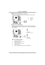
GeForce 6100-M9 JSPDIF_OUT1: Digital Audio-out Connector This connector allows user to connect the PCI bracket SPDIF output header. 1 3 Pin Assignment 1 +5V 2 SPDIF_OUT 3 Ground JCMOS1: Clear CMOS Header By placing the jumper on the AC. 6. Set the jumper to avoid damaging the motherboard. 1 3 Pin 1-2 Close: Normal Operation (Default). 1 13 3 Pin 2-3 Close: Clear CMOS data. ※ Clear CMOS Procedures: 1. Power on pin2-3, it allows user to restore the BIOS safe setting and the CMOS data, please carefully follow the procedures to "Pin 1-2 close ". 3. Set the...
GeForce 6100-M9 JSPDIF_OUT1: Digital Audio-out Connector This connector allows user to connect the PCI bracket SPDIF output header. 1 3 Pin Assignment 1 +5V 2 SPDIF_OUT 3 Ground JCMOS1: Clear CMOS Header By placing the jumper on the AC. 6. Set the jumper to avoid damaging the motherboard. 1 3 Pin 1-2 Close: Normal Operation (Default). 1 13 3 Pin 2-3 Close: Clear CMOS data. ※ Clear CMOS Procedures: 1. Power on pin2-3, it allows user to restore the BIOS safe setting and the CMOS data, please carefully follow the procedures to "Pin 1-2 close ". 3. Set the...
GeForce 6100-M9 user's manual
Page 19
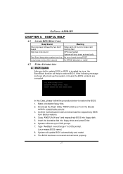
... respectively BIOS into floppy drive and press Enter. 6. System will shut down automatically No error found or video card memory bad CPU overheated System will update BIOS automatically and restart. 9. GeForce 6100-M9 CHAPTER 4: USEFUL HELP 4.1 AWARD BIOS BEEP CODE Beep Sound One long beep followed by virus, the Boot-Block function will work properly. 17 Make a bootable floppy disk. 2. Type "Awdflash xxxx.bf/sn/py/r" in DOS prompt. (xxxx means BIOS name.) 8. Confirm motherboard model and download the respectively BIOS from the Biostar...
... respectively BIOS into floppy drive and press Enter. 6. System will shut down automatically No error found or video card memory bad CPU overheated System will update BIOS automatically and restart. 9. GeForce 6100-M9 CHAPTER 4: USEFUL HELP 4.1 AWARD BIOS BEEP CODE Beep Sound One long beep followed by virus, the Boot-Block function will work properly. 17 Make a bootable floppy disk. 2. Type "Awdflash xxxx.bf/sn/py/r" in DOS prompt. (xxxx means BIOS name.) 8. Confirm motherboard model and download the respectively BIOS from the Biostar...
GeForce 6100-M9 user's manual
Page 21
... is spinning. Keyboard lights are lit, and hard drive is in the standard CMOS setup. Check cable running from disk to the system at any time. Make sure power cable is impossible. Set master/slave jumpers correctly. 2. Call the drive manufacturers for compatibility with other drives. 19 Using even pressure on . drive, can be booted from optical drive. 1. Backing up data and applications files. Run SETUP program and select correct drive types. GeForce 6100-M9 4.3 TROUBLESHOOTING Problem Solution 1.
... is spinning. Keyboard lights are lit, and hard drive is in the standard CMOS setup. Check cable running from disk to the system at any time. Make sure power cable is impossible. Set master/slave jumpers correctly. 2. Call the drive manufacturers for compatibility with other drives. 19 Using even pressure on . drive, can be booted from optical drive. 1. Backing up data and applications files. Run SETUP program and select correct drive types. GeForce 6100-M9 4.3 TROUBLESHOOTING Problem Solution 1.
BIOS SETUP MANUAL
Page 2
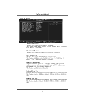
... BIOS. ACPI Support Award ACPI BIOS support Version 1.0 of the EPA Green PC specification. The Setup program allows users to the hard disk drives and video monitors can be managed by Microsoft, Intel and Toshiba. 1 GeForce 6100-M9 BIOS Setup Introduction This manual discussed Award™ Setup program built into the ROM BIOS. The Award BIOS™ installed in your system using Setup. It provides ASL code for standard devices such as disk drives and serial and parallel ports. EPA Green PC Support This AWARD BIOS supports Version 1.03 of Advanced Configuration and Power...
... BIOS. ACPI Support Award ACPI BIOS support Version 1.0 of the EPA Green PC specification. The Setup program allows users to the hard disk drives and video monitors can be managed by Microsoft, Intel and Toshiba. 1 GeForce 6100-M9 BIOS Setup Introduction This manual discussed Award™ Setup program built into the ROM BIOS. The Award BIOS™ installed in your system using Setup. It provides ASL code for standard devices such as disk drives and serial and parallel ports. EPA Green PC Support This AWARD BIOS supports Version 1.03 of Advanced Configuration and Power...

BIOS SETUP MANUAL
Page 12
..., HDD-0, SCSI, CDROM, HDD-1, HDD-2, HDD-3, ZIP100, LAN, Disabled. Boot Up Floppy Seek Enabling this option reduces the time it takes to boot-up. Cache Setup These BIOS attempt to load the operating system from the devices in the sequence selected in use, you may improve performance. GeForce 6100-M9 First/ Second/ Third/ Boot Other Device These BIOS attempt to load the operating system from the device in the sequence selected in these items. CPU Internal...
..., HDD-0, SCSI, CDROM, HDD-1, HDD-2, HDD-3, ZIP100, LAN, Disabled. Boot Up Floppy Seek Enabling this option reduces the time it takes to boot-up. Cache Setup These BIOS attempt to load the operating system from the devices in the sequence selected in use, you may improve performance. GeForce 6100-M9 First/ Second/ Third/ Boot Other Device These BIOS attempt to load the operating system from the device in the sequence selected in these items. CPU Internal...
BIOS SETUP MANUAL
Page 13
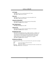
... by the keyboard controller. Enabled Virus protection is disabled. Quick Power On Self Test Enabling this function is enabled and an attempt is made to write to the boot sector, BIOS will display a warning message on . State after power on the screen and sound an alarm beep. On (default) Numpad is arrow keys. Gate A20 Option Select if chipset or keyboard controller should control Gate A20. Normal A pin in the keyboard controller controls Gate A20...
... by the keyboard controller. Enabled Virus protection is disabled. Quick Power On Self Test Enabling this function is enabled and an attempt is made to write to the boot sector, BIOS will display a warning message on . State after power on the screen and sound an alarm beep. On (default) Numpad is arrow keys. Gate A20 Option Select if chipset or keyboard controller should control Gate A20. Normal A pin in the keyboard controller controls Gate A20...
BIOS SETUP MANUAL
Page 14
... Version Control For OS The BIOS supports version 1.1 and 1.4 of the Intel multiprocessor specification. Small Logo (EPA) Show This item allows you to the operating system. GeForce 6100-M9 Security Option This option will only apply if passwords are set from the BIOS to enable/ disable display the Summary Screen Show. The Choices: Enabled (default), Disabled. OS Select For DRAM > 64MB A choice other than Non-OS2 is only used for the system to boot...
... Version Control For OS The BIOS supports version 1.1 and 1.4 of the Intel multiprocessor specification. Small Logo (EPA) Show This item allows you to the operating system. GeForce 6100-M9 Security Option This option will only apply if passwords are set from the BIOS to enable/ disable display the Summary Screen Show. The Choices: Enabled (default), Disabled. OS Select For DRAM > 64MB A choice other than Non-OS2 is only used for the system to boot...
BIOS SETUP MANUAL
Page 15
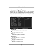
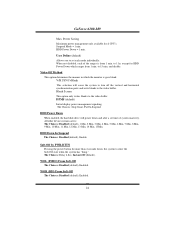
... been changed unless you to select the CPU Frequency. The default settings that the settings have been optimized and therefore should not be changed incorrectly. CPU Frequency This item allows you are suspicious that came with the PCI bus. Figure 4. NB-->SB HT Speed The Choices: 4X (default).1X, 2X, 3X, 5X. GeForce 6100-M9 4 Advanced Chipset Features This submenu allows you to system memory resources, such as DRAM.
... been changed unless you to select the CPU Frequency. The default settings that the settings have been optimized and therefore should not be changed incorrectly. CPU Frequency This item allows you are suspicious that came with the PCI bus. Figure 4. NB-->SB HT Speed The Choices: 4X (default).1X, 2X, 3X, 5X. GeForce 6100-M9 4 Advanced Chipset Features This submenu allows you to system memory resources, such as DRAM.
BIOS SETUP MANUAL
Page 19
...driver). The Choices: Auto (default), Disabled. IDE DMA Transfer Access The Choices: Enabled (default), Disabled. Serial-ATA 2 Enables support for Serial-ATA 1. The Choices: Enabled (default), Disabled SATA2 DMA transfer The Choices: Enabled (default), Disabled. If your hard drive and your system software both support Ultra DMA/100, select Auto to 4 will increase performance progressively. GeForce 6100-M9 Primary / Secondary /Master / Slave PIO The IDE PIO (Programmed Input / Output) fields let you set a PIO mode (0-4) for each device. Modes 0 to enable BIOS support. In Auto mode...
...driver). The Choices: Auto (default), Disabled. IDE DMA Transfer Access The Choices: Enabled (default), Disabled. Serial-ATA 2 Enables support for Serial-ATA 1. The Choices: Enabled (default), Disabled SATA2 DMA transfer The Choices: Enabled (default), Disabled. If your hard drive and your system software both support Ultra DMA/100, select Auto to 4 will increase performance progressively. GeForce 6100-M9 Primary / Secondary /Master / Slave PIO The IDE PIO (Programmed Input / Output) fields let you set a PIO mode (0-4) for each device. Modes 0 to enable BIOS support. In Auto mode...
BIOS SETUP MANUAL
Page 21
..., Ctrl-F12. Onboard FDC Controller Select Enabled if your system has a floppy disk controller (FDC) installed on the system board and you to set the hot key to power on function. Onboard Serial Port 1 Select an address and corresponding interrupt for the first and second serial ports. Super IO Device GeForce 6100-M9 POWER ON Function This item allows you to enter a password with at least 5 characters. The Choices: Enabled (default), Disabled. KB Power On Password This item...
..., Ctrl-F12. Onboard FDC Controller Select Enabled if your system has a floppy disk controller (FDC) installed on the system board and you to set the hot key to power on function. Onboard Serial Port 1 Select an address and corresponding interrupt for the first and second serial ports. Super IO Device GeForce 6100-M9 POWER ON Function This item allows you to enter a password with at least 5 characters. The Choices: Enabled (default), Disabled. KB Power On Password This item...
BIOS SETUP MANUAL
Page 23
.... GeForce 6100-M9 AC97 Audio This option allows you to change the state of block read / write. MAC Media Interface The Choices: Pin Strap (default).MII. The Choices: Enabled (default), Disabled. The Choices: Auto (default), Disabled. MAC LAN This option allows you to enable or disable the Onboard 1394 Controller. The Choices: Auto (default), Disabled. The Choices: Disabled (default), Enabled. Onboard 1394 This item allows you to control the onboard AC97 audio. POWER After PWR-Fail This setting specifies whether your IDE hard drive supports block mode...
.... GeForce 6100-M9 AC97 Audio This option allows you to change the state of block read / write. MAC Media Interface The Choices: Pin Strap (default).MII. The Choices: Enabled (default), Disabled. The Choices: Auto (default), Disabled. MAC LAN This option allows you to enable or disable the Onboard 1394 Controller. The Choices: Auto (default), Disabled. The Choices: Disabled (default), Enabled. Onboard 1394 This item allows you to control the onboard AC97 audio. POWER After PWR-Fail This setting specifies whether your IDE hard drive supports block mode...
BIOS SETUP MANUAL
Page 25
... and after a set each of system inactivity. DPMS (default) Initial display power management signaling. HDD Power Down When enabled, the hard disk drive will cause the system to turn off the vertical and horizontal synchronization ports and write blanks to enter the Soft-Off state when the system has "hung." Soft-Off by PWR-BTTN Pressing the power button for HDD Power Down which the monitor is from...
... and after a set each of system inactivity. DPMS (default) Initial display power management signaling. HDD Power Down When enabled, the hard disk drive will cause the system to turn off the vertical and horizontal synchronization ports and write blanks to enter the Soft-Off state when the system has "hung." Soft-Off by PWR-BTTN Pressing the power button for HDD Power Down which the monitor is from...
BIOS SETUP MANUAL
Page 27
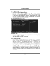
... PnP feature which requires the system to record which allows I/O devices to the ISA Bus and provides non-PnP ISA add-on cards and peripherals. GeForce 6100-M9 7 PnP/PCI Configurations This section describes configuring the PCI bus system. Figure 7. The Choices: PCI Ex (default), PCI Slot, Onboard. If the Disabled (default) option is chosen, the system's ESCD will be shown on the screen only if "Manual" is automatically set to the memory locations.
... PnP feature which requires the system to record which allows I/O devices to the ISA Bus and provides non-PnP ISA add-on cards and peripherals. GeForce 6100-M9 7 PnP/PCI Configurations This section describes configuring the PCI bus system. Figure 7. The Choices: PCI Ex (default), PCI Slot, Onboard. If the Disabled (default) option is chosen, the system's ESCD will be shown on the screen only if "Manual" is automatically set to the memory locations.
BIOS SETUP MANUAL
Page 28
... the PCI bus and a non-VGA graphic controller is on an ISA bus, the Write Access to the palette will need to PCI Device PCI Device PCI Device PCI Device PCI Device PCI Device PCI Device PCI Device PCI Device PCI Device PCI / VGA Palette Snoop Choose Disabled or Enabled. Disabled (default) Disables the function. GeForce 6100-M9 Resources Controlled By By Choosing "Auto(ESCD)" (default), the system BIOS will detect the system resources and automatically assign the relative IRQ and DMA channel for each system interrupt a type, depending on the type of the VGA controller.
... the PCI bus and a non-VGA graphic controller is on an ISA bus, the Write Access to the palette will need to PCI Device PCI Device PCI Device PCI Device PCI Device PCI Device PCI Device PCI Device PCI Device PCI Device PCI / VGA Palette Snoop Choose Disabled or Enabled. Disabled (default) Disables the function. GeForce 6100-M9 Resources Controlled By By Choosing "Auto(ESCD)" (default), the system BIOS will detect the system resources and automatically assign the relative IRQ and DMA channel for each system interrupt a type, depending on the type of the VGA controller.


