Bios Setup
Page 4
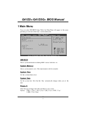
...F1 General Help F10 Save and Exit ESC Exit vxx.xx (C)Copyright 1985-200x, American Megatrends, Inc. System Memory Shows system memory size, VGA shard memory will appear on the screen providing an overview of floppy disk drive installed in / None 3 Options: 360K,... 5.25 in / 1.2M, 5.25 in / 720K, 3.5 in / 1.44M, 3.5 in / 2.88M, 3.5 in your system. System Time System Date Floppy A > IDE Configuration [ 00:00:00] [Fri 01/01/2010] Select Screen Select Item +- G41D3...
...F1 General Help F10 Save and Exit ESC Exit vxx.xx (C)Copyright 1985-200x, American Megatrends, Inc. System Memory Shows system memory size, VGA shard memory will appear on the screen providing an overview of floppy disk drive installed in / None 3 Options: 360K,... 5.25 in / 1.2M, 5.25 in / 720K, 3.5 in / 1.44M, 3.5 in / 2.88M, 3.5 in your system. System Time System Date Floppy A > IDE Configuration [ 00:00:00] [Fri 01/01/2010] Select Screen Select Item +- G41D3...

Bios Setup
Page 9
Options: Disabled (Default) / Enabled 8 G41D3+/G41D3G+ BIOS M anual Intel(R) SpeedStep(tm) Tech T his item allows you to... the CPUID instruction to identify the processor and its requirements and prefetches dat a and instructions from the memory into some Intel processors that allows the clock speed o f the processor to be dynamically changed by ...query the processor to enable SpeedStep technology for a 64-byte cach e line. T his reduces the latency associated with memory reads. Options: Enabled (Default) / Disabled Max CPUID Value Limit When the computer is not working. Befo re it...
Options: Disabled (Default) / Enabled 8 G41D3+/G41D3G+ BIOS M anual Intel(R) SpeedStep(tm) Tech T his item allows you to... the CPUID instruction to identify the processor and its requirements and prefetches dat a and instructions from the memory into some Intel processors that allows the clock speed o f the processor to be dynamically changed by ...query the processor to enable SpeedStep technology for a 64-byte cach e line. T his reduces the latency associated with memory reads. Options: Enabled (Default) / Disabled Max CPUID Value Limit When the computer is not working. Befo re it...
Bios Setup
Page 12
... should behave after a power fail or interrupts occurs. CPU Temperature SYS Temperature CPU Fan System1 Fan +12.0V +5.00V CPU Voltage Chipset Voltage FSB Voltage Memory Voltage Select Screen Select Item +- G41D3+/G41D3G+ BIOS M anual Stroke Keys Selected T his item will show PC health status during POST stage.
... should behave after a power fail or interrupts occurs. CPU Temperature SYS Temperature CPU Fan System1 Fan +12.0V +5.00V CPU Voltage Chipset Voltage FSB Voltage Memory Voltage Select Screen Select Item +- G41D3+/G41D3G+ BIOS M anual Stroke Keys Selected T his item will show PC health status during POST stage.
Bios Setup
Page 16
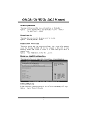
...the Wake on LAN (WOL) jumper on LAN function. Options: Disabled (Default) / Enabled Resume On RTC Alarm When " Enabled", you can set the memory address of HPET . Options: Disabled (Default) / Enabled High Performance Event Timer T his item allows you to enable or disabled the USB resume from S3.../S4 function. G41D3+/G41D3G+ BIOS M anual USB Dev ice Wakeup from S3/S4 T his item allows you to enable or disabled the HPET. Options: FED00000h (Default) /...
...the Wake on LAN (WOL) jumper on LAN function. Options: Disabled (Default) / Enabled Resume On RTC Alarm When " Enabled", you can set the memory address of HPET . Options: Disabled (Default) / Enabled High Performance Event Timer T his item allows you to enable or disabled the USB resume from S3.../S4 function. G41D3+/G41D3G+ BIOS M anual USB Dev ice Wakeup from S3/S4 T his item allows you to enable or disabled the HPET. Options: FED00000h (Default) /...
Bios Setup
Page 20
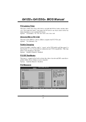
G41D3+/G41D3G+ BIOS M anual PCI Latency Timer T his item controls how long ...Disabled (Default) / Enabled PCI IDE BusMaster T his item allows BIOS to choose a IRQ to perform DMA (Direct Memory Access) trans fers. Change Option F1 General Help F10 Save and Exit ESC Exit vxx.xx (C)Copyright 1985-200x, ... palette and then map it over . DMA Channel 0 DMA Channel 1 DMA Channel 3 DMA Channel 5 DMA Channel 6 DMA Channel 7 Reserved Memory Size [Available] [Available] [Available] [Available] [Available] [Available] [Disabled] Select Screen Select Item +- Options: Yes (Default) / No...
G41D3+/G41D3G+ BIOS M anual PCI Latency Timer T his item controls how long ...Disabled (Default) / Enabled PCI IDE BusMaster T his item allows BIOS to choose a IRQ to perform DMA (Direct Memory Access) trans fers. Change Option F1 General Help F10 Save and Exit ESC Exit vxx.xx (C)Copyright 1985-200x, ... palette and then map it over . DMA Channel 0 DMA Channel 1 DMA Channel 3 DMA Channel 5 DMA Channel 6 DMA Channel 7 Reserved Memory Size [Available] [Available] [Available] [Available] [Available] [Available] [Disabled] Select Screen Select Item +- Options: Yes (Default) / No...

Bios Setup
Page 21
G41D3+/G41D3G+ BIOS M anual IRQ3/4/5/7/9/10/11/14/15 T hese items will allow you to assign automatically. T he option "Available" means the IRQ is going to ... Active State Power-Management[Disabled] Enable/Disable PCI Express L0s and L1 link power states. Options: Available (Default) / Reserved Reserved Memory Size T his function is going to reserve cert ain memory size for the PCI Express devices b efore the operating system boots. T his item allows BIOS to assign automatically. Select Screen Select...
G41D3+/G41D3G+ BIOS M anual IRQ3/4/5/7/9/10/11/14/15 T hese items will allow you to assign automatically. T he option "Available" means the IRQ is going to ... Active State Power-Management[Disabled] Enable/Disable PCI Express L0s and L1 link power states. Options: Available (Default) / Reserved Reserved Memory Size T his function is going to reserve cert ain memory size for the PCI Express devices b efore the operating system boots. T his item allows BIOS to assign automatically. Select Screen Select...

Bios Setup
Page 25
... on your system. Notice z Beware of that setting inappropriate values in below sections may cause system to malfunction. G41D3+/G41D3G+ BIOS M anual 5 Chipset Menu T his chipset manage bus speeds and access to system memory resources, such as DRAM. T his submenu allows you to configure the speci fic features of this menu may...
... on your system. Notice z Beware of that setting inappropriate values in below sections may cause system to malfunction. G41D3+/G41D3G+ BIOS M anual 5 Chipset Menu T his chipset manage bus speeds and access to system memory resources, such as DRAM. T his submenu allows you to configure the speci fic features of this menu may...

Bios Setup
Page 26
...+- C hange Option F1 G eneral Help F1 0 S ave and Exit ES C E xit vxx.xx (C)C opyright 198 5-200x, Amer ican Megatre nds, Inc. G41D3+/G41D3G+ BIOS M anual North Bridge Configuration BIOS S ETUP UTILITY Chips et North Bridge Chips et Configura tion Memor y Remap Featu re PCI MMIO Allocat ion...T his item allows you to enable or disable the remapping of the overlapped PCI memory above the total physical memory. DISA BLE: Do not allow rema pping of system memory for the memory requirements. Memory Remap Feature T his item allows you to enable or disable VGA controller. When ...
...+- C hange Option F1 G eneral Help F1 0 S ave and Exit ES C E xit vxx.xx (C)C opyright 198 5-200x, Amer ican Megatre nds, Inc. G41D3+/G41D3G+ BIOS M anual North Bridge Configuration BIOS S ETUP UTILITY Chips et North Bridge Chips et Configura tion Memor y Remap Featu re PCI MMIO Allocat ion...T his item allows you to enable or disable the remapping of the overlapped PCI memory above the total physical memory. DISA BLE: Do not allow rema pping of system memory for the memory requirements. Memory Remap Feature T his item allows you to enable or disable VGA controller. When ...

Bios Setup
Page 27
DVMT will set the optimum amount of memory to be allocated for " Dynamic Video Memory T echnology". Options: Disabled (Default) / Enabled 26 C hange Option F1 G eneral Help F1 0 S ave and Exit ES C E xit vxx.xx (C)C opyright 198 5-200x, Amer... respond to system requirements and applications demands, by allocating the proper amount of the unified memory architecture (UMA) concept. Options: DVMT Mode (Default) DVMT/FIXED Memory DVMT stands for a balance between graphics and system perform ance. G41D3+/G41D3G+ BIOS M anual PEG Port T his item allows you to control the spread ...
DVMT will set the optimum amount of memory to be allocated for " Dynamic Video Memory T echnology". Options: Disabled (Default) / Enabled 26 C hange Option F1 G eneral Help F1 0 S ave and Exit ES C E xit vxx.xx (C)C opyright 198 5-200x, Amer... respond to system requirements and applications demands, by allocating the proper amount of the unified memory architecture (UMA) concept. Options: DVMT Mode (Default) DVMT/FIXED Memory DVMT stands for a balance between graphics and system perform ance. G41D3+/G41D3G+ BIOS M anual PEG Port T his item allows you to control the spread ...
Bios Setup
Page 30
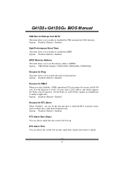
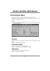
... Control by superio PSI Control CPU Frequency Setting PCIE Clock By PCIE Frequency Setting [Enabled] [200] [Auto] [100] CPU Voltage FSB Voltage Memory Voltage Chipset Voltage DRAM Frequency Configure DRAM Timing by SPD [Default] [Default] [Default] [Default] [Auto] [Enabled] Select Screen Select Item ... Help F10 Save and Exit ESC Exit vxx.xx (C)Copyright 1985-200x, American Megatrends, Inc. Options: 200 (Default) / Min= 100MHz; G41D3+/G41D3G+ BIOS M anual 6 Performance Menu T his submenu allows you to malfunction. Changing the voltage and clock improperly may damage the device.) ...
... Control by superio PSI Control CPU Frequency Setting PCIE Clock By PCIE Frequency Setting [Enabled] [200] [Auto] [100] CPU Voltage FSB Voltage Memory Voltage Chipset Voltage DRAM Frequency Configure DRAM Timing by SPD [Default] [Default] [Default] [Default] [Auto] [Enabled] Select Screen Select Item ... Help F10 Save and Exit ESC Exit vxx.xx (C)Copyright 1985-200x, American Megatrends, Inc. Options: 200 (Default) / Min= 100MHz; G41D3+/G41D3G+ BIOS M anual 6 Performance Menu T his submenu allows you to malfunction. Changing the voltage and clock improperly may damage the device.) ...

Bios Setup
Page 31
... DRAM tCL Options: 6 (Default) / 3 ~ 10 DRAM tRAS Options: 15 (Default) / 9 ~ 24 DRAM tRP Options: 6 (Default) / 3 ~ 10 30 DRAM Frequency T his item allows you to select Memory Voltage Control. Max=150 CPU Voltage T his item allows you to select FSB Voltage Control. FS B Voltage T his item allows you to select CPU Voltage... Control. Chipset Voltage T his item allows you to select the PCIE clock control Options: 100 (Default) / Min=100; G41D3+/G41D3G+ BIOS M anual PCIE Frequency Setting T his item allows you to select Chipset Voltage Control.
... DRAM tCL Options: 6 (Default) / 3 ~ 10 DRAM tRAS Options: 15 (Default) / 9 ~ 24 DRAM tRP Options: 6 (Default) / 3 ~ 10 30 DRAM Frequency T his item allows you to select Memory Voltage Control. Max=150 CPU Voltage T his item allows you to select FSB Voltage Control. FS B Voltage T his item allows you to select CPU Voltage... Control. Chipset Voltage T his item allows you to select the PCIE clock control Options: 100 (Default) / Min=100; G41D3+/G41D3G+ BIOS M anual PCIE Frequency Setting T his item allows you to select Chipset Voltage Control.

Setup Manual
Page 2
... 1: Introduction 1 1.1 Before You Start 1 1.2 Package Checklist 1 1.3 Motherboard Features 2 1.4 Rear Panel Connectors 3 1.5 Motherboard Layout 4 Chapter 2: Hardware Installation 5 2.1 Installing Central Processing Unit (CPU 5 2.2 FAN Headers 7 2.3 Installing System Memory 8 2.4 Connectors and Slots 10 Chapter 3: Headers & Jumpers Setup 12 3.1 How to Setup Jumpers 12 3.2 Detail Settings 12 Chapter 4: Useful Help 18 4.1 Driver Installation Note 18...
... 1: Introduction 1 1.1 Before You Start 1 1.2 Package Checklist 1 1.3 Motherboard Features 2 1.4 Rear Panel Connectors 3 1.5 Motherboard Layout 4 Chapter 2: Hardware Installation 5 2.1 Installing Central Processing Unit (CPU 5 2.2 FAN Headers 7 2.3 Installing System Memory 8 2.4 Connectors and Slots 10 Chapter 3: Headers & Jumpers Setup 12 3.1 How to Setup Jumpers 12 3.2 Detail Settings 12 Chapter 4: Useful Help 18 4.1 Driver Installation Note 18...
Setup Manual
Page 4
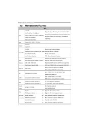
SATA Version 2.0 specification compliant Realtek RTL 8103EL (G41D3+) LAN Realtek RTL 8111DL (G41D3G+) 10 / 100 Mb/s auto negotiation 10 / 100 Mb/s / 1Gb/s auto negotiation Sound Codec ALC662 / VT1708B 5.1 channels audio ...Hyper-Threading / Execute Disable Bit / Intel Core2Duo / Core2Quad / Enhanced Intel SpeedStep® / Intel Architecture-64 / CPU Pentium Dual-Core / Celeron Dual-Core / Extended Memory 64 Technology / Virtualization Celeron 4xx processor Technology (Maximum Watt: 95W) FSB Support 800 / 1066 / 1333 MHz Chipset Intel G41 Intel ICH7 ITE 8721 Environment Control...
SATA Version 2.0 specification compliant Realtek RTL 8103EL (G41D3+) LAN Realtek RTL 8111DL (G41D3G+) 10 / 100 Mb/s auto negotiation 10 / 100 Mb/s / 1Gb/s auto negotiation Sound Codec ALC662 / VT1708B 5.1 channels audio ...Hyper-Threading / Execute Disable Bit / Intel Core2Duo / Core2Quad / Enhanced Intel SpeedStep® / Intel Architecture-64 / CPU Pentium Dual-Core / Celeron Dual-Core / Extended Memory 64 Technology / Virtualization Celeron 4xx processor Technology (Maximum Watt: 95W) FSB Support 800 / 1066 / 1333 MHz Chipset Intel G41 Intel ICH7 ITE 8721 Environment Control...

Setup Manual
Page 10
DDR3_A1 DDR3_B1 Motherboard Manual 2.3 INSTALLING SYSTEM MEMORY A. Insert the DIMM vertically and firmly into the slot until the retaining chip snap back in place and the DIMM is properly seated. 8 DDR3 module 1. Align a DIMM on the slot such that the notch on the DIMM matches the break on the Slot. 2. Unlock a DIMM slot by pressing the retaining clips outward.
DDR3_A1 DDR3_B1 Motherboard Manual 2.3 INSTALLING SYSTEM MEMORY A. Insert the DIMM vertically and firmly into the slot until the retaining chip snap back in place and the DIMM is properly seated. 8 DDR3 module 1. Align a DIMM on the slot such that the notch on the DIMM matches the break on the Slot. 2. Unlock a DIMM slot by pressing the retaining clips outward.

Setup Manual
Page 11
B. C. Dual Channel Memory Installation Please refer to the following requirements to activate Dual Channel function: Install memory module of the memory module must be the same(x8 or x16) 9 Memory Capacity G41D3+/G41D3G+ DIMM Socket Location DDR3_A1 DDR3_B1 DDR3 Module 256MB/512MB/1GB/2GB/4GB 256MB/512MB/1GB/2GB/4GB Total Memory Size Max is 8GB. Dual Channel Status DDR3_A1 DDR3_B1 Disabled O X Disabled X O Enabled O O (O means memory installed; X, not installed.) The DRAM bus width of the same density in pairs, shown in the table.
B. C. Dual Channel Memory Installation Please refer to the following requirements to activate Dual Channel function: Install memory module of the memory module must be the same(x8 or x16) 9 Memory Capacity G41D3+/G41D3G+ DIMM Socket Location DDR3_A1 DDR3_B1 DDR3 Module 256MB/512MB/1GB/2GB/4GB 256MB/512MB/1GB/2GB/4GB Total Memory Size Max is 8GB. Dual Channel Status DDR3_A1 DDR3_B1 Disabled O X Disabled X O Enabled O O (O means memory installed; X, not installed.) The DRAM bus width of the same density in pairs, shown in the table.
Setup Manual
Page 27
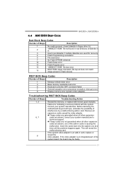
...layout does not match image present in flash device) POST BIOS Beep Codes Number of Beeps Description 1 Memory refresh timer error 3 Base memory read/write test error 6 Keyboard controller BAT command failed 7 General exception error (processor exception interrupt error) 8 Display... cards are absent, one at a time until the problem happens again. Consult your system manufacturer's technical support. 4.4 AMI BIOS BEEP CODE G41D3+/G41D3G+ Boot Block Beep Codes Number of Beeps Description 1 No media present. (Insert diskette in floppy drive A:) 2 "AMIBOOT.ROM" file...
...layout does not match image present in flash device) POST BIOS Beep Codes Number of Beeps Description 1 Memory refresh timer error 3 Base memory read/write test error 6 Keyboard controller BAT command failed 7 General exception error (processor exception interrupt error) 8 Display... cards are absent, one at a time until the problem happens again. Consult your system manufacturer's technical support. 4.4 AMI BIOS BEEP CODE G41D3+/G41D3G+ Boot Block Beep Codes Number of Beeps Description 1 No media present. (Insert diskette in floppy drive A:) 2 "AMIBOOT.ROM" file...


